EP0222854B1 - Fernsteuereinheit für geräte der unterhaltungselektronik - Google Patents
Fernsteuereinheit für geräte der unterhaltungselektronik Download PDFInfo
- Publication number
- EP0222854B1 EP0222854B1 EP86903318A EP86903318A EP0222854B1 EP 0222854 B1 EP0222854 B1 EP 0222854B1 EP 86903318 A EP86903318 A EP 86903318A EP 86903318 A EP86903318 A EP 86903318A EP 0222854 B1 EP0222854 B1 EP 0222854B1
- Authority
- EP
- European Patent Office
- Prior art keywords
- control
- telecontrol unit
- telecontrol
- remote control
- slide
- Prior art date
- Legal status (The legal status is an assumption and is not a legal conclusion. Google has not performed a legal analysis and makes no representation as to the accuracy of the status listed.)
- Expired - Lifetime
Links
Images
Classifications
-
- H—ELECTRICITY
- H04—ELECTRIC COMMUNICATION TECHNIQUE
- H04B—TRANSMISSION
- H04B1/00—Details of transmission systems, not covered by a single one of groups H04B3/00 - H04B13/00; Details of transmission systems not characterised by the medium used for transmission
- H04B1/06—Receivers
- H04B1/16—Circuits
- H04B1/20—Circuits for coupling gramophone pick-up, recorder output, or microphone to receiver
- H04B1/202—Circuits for coupling gramophone pick-up, recorder output, or microphone to receiver by remote control
-
- H—ELECTRICITY
- H01—ELECTRIC ELEMENTS
- H01H—ELECTRIC SWITCHES; RELAYS; SELECTORS; EMERGENCY PROTECTIVE DEVICES
- H01H9/00—Details of switching devices, not covered by groups H01H1/00 - H01H7/00
- H01H9/02—Bases, casings, or covers
- H01H9/0214—Hand-held casings
- H01H9/0235—Hand-held casings specially adapted for remote control, e.g. of audio or video apparatus
Definitions
- the innovation deals with a remote control unit for consumer electronics devices.
- remote control units for television receivers, for video recorders and hi-fi systems.
- the function of the television receiver and video recorder is directly dependent on one another, since the stored information of the video recorder is only visible or audible via a television receiver during playback.
- a separate remote control unit is assigned to each, i.e. Two remote control units must be used for the optimal playback of a program recorded on a magnetic tape.
- the video recorder receives the switch-on command as well as the start and channel selection command via its remote control unit and the television receiver receives the analogue manipulated variables via its assigned remote control unit, e.g. Switch on / off, volume, image brightness, color contrast transmitted. If you want to search for different sections on a magnetic tape, it is necessary to constantly work with two remote control units in order to achieve an optimal setting or playback.
- remote control units have received a range of operating functions which go far beyond the pure functions of television and video remote controls.
- the task is to create a single remote control unit that is tailor-made for several device types.
- the new remote control unit is divided into three operating segments 1-3.
- the common controls are housed, with which both the television receiver and the video recorder are to be operated remotely, e.g. for the channels and the tuner functions.
- the controls which are only geared towards video recorder operation, such as start, stop, fast forward, rewind, record, play back and the lower segment 3 is specially designed for the television receiver functions, e.g. Color contrast and image brightness.
- the slide 4 has on its side edges skid-like designs 8 with which it is slidably arranged in the grooves 5 in the remote control unit.
- the slider is slidable in such a way that it sweeps over the two lower segments 2, 3 and when one of these two lower segments is covered, the other segment is exposed. . If the slide 4 is pushed over the middle segment 2, the segments 1 and 3 are exposed, i.e. the television receiver can be operated remotely. If the slider 4 is pushed over the segment 3, the segments 1 and 2 are exposed, which means that the controls for the video recorder are now exposed. Since the segment that is not required is covered by the slide, incorrect loads are excluded. Exact operation of the remote control unit is guaranteed even in a room that is only moderately lit.
- An advantageous further development of the remote control unit according to the invention is to design the operating segments that are specially adapted to the individual devices to be switched on or off, and to simultaneously change the code of the remote control signal with this switchover so that only the operating functions or devices are addressed.
- a nose 7 in the remote control unit which is arranged on one of the two skid-like designs 8 and projects through the groove 5 of the remote control unit into the remote control unit, is not shown here Switch operated. If the slider 4 is above the lower segment 3, the controls for the video recorder are switched on. If, on the other hand, the slide 4 is above the segment 2, the control elements for the television receiver are switched on. The common controls of the upper operating segment 1 are always switched on.
- the slider 4 can also be comprising the remote control unit, slidably arranged in grooves 6 of the remote control unit (FIG. 3). It is also conceivable that other consumer electronics devices can be combined in different combinations in the same way.
Description
- Die Neuerung befaßt sich mit einer Fernsteuereinheit für Geräte der Unterhaltungselektronik.
- Es ist bekannt, die Bedienungsfunktionen von Geräten der Unterhaltungselektronik mittels drahtloser Fernbedienungen fernzusteuern.
- So gibt es beispielsweise Fernsteuereinheiten für Fernsehempfänger, für Videorecorder und HiFi-Anlagen. Im direkten voneinander anhängigen Zusammenhang stehen hier funktionsgemäß Fernsehempfänger und Videorecorder, da bei Wiedergabe die gespeicherten Informationen des Videorecorders nur über eine Fernsehempfänger sichtbar bzw. hörbar sind. Sind beide Geräte fernbedienbar, ist beiden je eine separate Fernsteuereinheit zugeordnet, d.h. für die optimale Wiedergabe einer auf einem Magnetband aufgezeichneten Sendung müssen zwei Fernsteuereinheiten zu Hilfe genommen werden. Der Videorecorder bekommt über seine Fernsteuereinheit den Einschalt- sowie den Start- und Kanalwahlbefehl und dem Fernsehempfänger werden über seine zugeordnete Fernsteuereinheit die analogen Stellgrößen wie z.B. Ein- /Ausschalten, Lautstärke, Bildhelligkeit, Farbkontrast übermittelt. Will man veschiedene Ausschnitte auf einem Magnetband suchen ist es erforderlich, ständig mit zwei Fernsteuereinhenten zu hantieren, um jeweils eine optimale Einstellung bzw. Wiedergabe zu erreichen.
- Aus der DE-A-3 003 425 ist schon bekannt, verschiedene Geräte mittels einer einzigen Fernbedienung an zusteuern.
- Außerdem haben heute, insbesondere bei Mikroprozessorgeräten, Fernsteuereinheiten einen weit über die reinen Funktionen von Fernseh- und Video- Fernbedienungen hinausgehenden Umfang an Bedienungsfunktionen erhalten.
- Um eine hierdurch bedingte Bedienungsvielfalt und Unsicherheit einzuschränken, wird die Aufgabe gestellt, eine einzige, für mehrere Gerätetypen maßgeschneiderte Fernsteuereinheit zu schaffen.
- Diese Aufgabe wird durch die in den Ansprüchen angegebene Neuerung gelöst.
- Die durch diese Erfindung erzielten Vorteile ergeben sich durch die Möglichkeit, unterschiedlich wertige Elemente nach Wunsch mischen zu können und beide Geräte-Einheiten mit nur einer Fernsteuereinheit bedienen zu können. An sich ist schon aus den Patent Abstracts of Japan, Band 5, Nr. 74 (E57) (746) 16. Mai 1981 (JP-A-5 624 022) bekannt, Teile eines Empfängers zu verdecken, um Fehlbedienungen zu vermeiden. Anhand der Figuren 1 bis 4 wird die Erfindung erlautert.
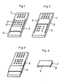
- Fig. 1 zeigt die neuerungsgemäße Fernsteuereinheit programmiert für die Ferbedienung eines Fernsehempfängers;
- Fig. 2 zeigt die neuerungsgemäße Fernsteuereinheit programmiert für die Fernbedienung eines Videorecorders;
- Fig. 3 zeigt eine Ausführungsvariante der neuerungsgemäßen Fernsteuereinheit;
- Fig. 4 zeigt den für die Programmierung vorgesehenen Schieber.
- Die neuerungsgemäße Fernsteuereinheit ist unterteilt in drei Bedienungssegmente 1-3. Beispielsweise sind im oberen Segment 1 die gemeinsamen Bedienungselemente untergebracht, mit denen sowohl der Fernsehempfänger als auch der Videorecorder fernbedient werden sollen, z.B. für die Kanäle und die Tuner-Funktionen. Im mittleren Segment 2 befinden sich die Bedienungselemente, die nur auf den Videorecorder-Betrieb abgestellt sind, wie Start, Stop, Vorlauf, Rücklauf, Aufnahme, Wiedergabe und das untere Segment 3 ist speziell auf die Fernsehempfänger-Funktionen ausgerichtet, wie z.B. Farbkontrast und Bildhelligkeit.
- Der Schieber 4 hat an seinen Seitenkanten kufenartige Ausbildungen 8 mit denen er in in der Fernsteuereinheit vorhandenen Nuten 5 gleitbar angeordnet ist.
- So ist der Schieber schiebbar derart, daß er die beiden unteren Segmente 2, 3 überstreicht und beim überdecken eines dieser beiden unteren Segmente jeweils das andere Segment freiliegt. . Wird der Schieber 4 über das mittlere Segmente 2 geschoben, so liegen die Segmente 1 und 3 frei, d.h. der Fernsehempfänger kann fernbedient werden. Wird der Schieber 4 über das Segment 3 geschoben, liegen die Segmente 1 und 2 frei, was bedeutet, daß jetzt die Bedienungselemente für den Videorecorder freiliegen. Da jeweils das nicht benötigte Segment von dem Schieber abgedeckt ist, sind Fehlbdienungen ausgeschlossen. Auch in einem nur maßig beleuchteten Raum ist eine exakte Bedienung der Fernsteuereinheit gewährleistet.
- Eine vorteilhafte Weiterbildung der neuerungsgemäßen Fernsteuereinheit liegt darin, die speziell auf die einzelnen Geräte abgestimmten Bedienungssegmente ein- oder abschaltbar auszuführen, und mit dieser Umschaltung gleichzeitig den Code des Fernsteuereinsignals zu ändern damit nur die bedienenden Funktionen oder Geäte angesprochen werden.
- Um somit die Fernsteuereinheit jeweils auf Fernseh- oder Videorecorderbetrieb zu schalten, wird neuerungsgemäß beim Verschieben des Schiebers 4 durch eine an einer der beiden kufenartigen Ausbildungen 8 angeordnete durch die eine Nut 5 der Fernsteuereinheit in die Fernsteuereinheit ragende Nase 7 in der Fernsteuereinheit ein hier nicht dargestellter Schalter betätigt. Befindet sich der Schieber 4 über dem unteren Segment 3, sind die Bedienungselemente für den Videorecorder eingeschaltet. Befindet sich dagegen der Schieber 4 über dem Segment 2, sind die Bedienungselemente für den Fernsehempfänger eingeschaltet. Die gemeinsamen Bedienungselemente des oberen Bedienungssegments 1 sind immer eingeschaltet.
- Es ist selbstverständlich, daß die Bedienungssegmente auch in anderer Reihenfolge aufgeteilt sein können. Auch kann der Schieber 4 seitlich, die Fernsteuereinheit umfassend, in Nuten 6 der Fernsteuereinheit gleitend angeordnet sein (Fig. 3). Es ist genauso denkbar, daß andere Geräte der Unterhaltungselektronik in unterschiedlicher Zusammenstellung auf gleiche Weise kombinierbar sind.
Claims (7)
Priority Applications (1)
| Application Number | Priority Date | Filing Date | Title |
|---|---|---|---|
| AT86903318T ATE54784T1 (de) | 1985-05-13 | 1986-05-10 | Fernsteuereinheit fuer geraete der unterhaltungselektronik. |
Applications Claiming Priority (2)
| Application Number | Priority Date | Filing Date | Title |
|---|---|---|---|
| DE8514075U | 1985-05-13 | ||
| DE8514075U DE8514075U1 (de) | 1985-05-13 | 1985-05-13 | Fernsteuereinheit für Geräte der Unterhaltungselektronik |
Publications (2)
| Publication Number | Publication Date |
|---|---|
| EP0222854A1 EP0222854A1 (de) | 1987-05-27 |
| EP0222854B1 true EP0222854B1 (de) | 1990-07-18 |
Family
ID=6781043
Family Applications (1)
| Application Number | Title | Priority Date | Filing Date |
|---|---|---|---|
| EP86903318A Expired - Lifetime EP0222854B1 (de) | 1985-05-13 | 1986-05-10 | Fernsteuereinheit für geräte der unterhaltungselektronik |
Country Status (6)
| Country | Link |
|---|---|
| EP (1) | EP0222854B1 (de) |
| JP (1) | JPS62502017A (de) |
| DE (2) | DE8514075U1 (de) |
| DK (1) | DK15987A (de) |
| SG (1) | SG8792G (de) |
| WO (1) | WO1986006897A1 (de) |
Families Citing this family (7)
| Publication number | Priority date | Publication date | Assignee | Title |
|---|---|---|---|---|
| DE3705238A1 (de) * | 1986-03-08 | 1988-09-01 | Telefonbau & Normalzeit Gmbh | Endgeraet mit einem, eine tastatur tragenden, verschiebbaren schlitten |
| DE3713428A1 (de) * | 1987-04-22 | 1988-11-03 | Unterhaltungselectronic Ohg De | Fernbedieneinheit fuer elektrische geraete |
| JPH03205677A (ja) * | 1990-01-05 | 1991-09-09 | Pioneer Electron Corp | 音響映像機器の制御方法 |
| DE9208072U1 (de) * | 1992-06-16 | 1992-08-13 | Grundig E.M.V. Elektro-Mechanische Versuchsanstalt Max Grundig Hollaend. Stiftung & Co Kg, 8510 Fuerth, De | |
| JP3844897B2 (ja) * | 1998-12-04 | 2006-11-15 | 株式会社マキタ | 電動工具のスイッチ |
| FR2936471B1 (fr) * | 2008-10-01 | 2011-12-09 | Valeo Securite Habitacle | Module d'identification pour vehicule automobile. |
| CN102544502B (zh) * | 2010-12-09 | 2015-07-01 | 中国科学院宁波材料技术与工程研究所 | 用于锂二次电池的正极负极导电添加剂及其制备方法和相关锂二次电池的制备方法 |
Family Cites Families (4)
| Publication number | Priority date | Publication date | Assignee | Title |
|---|---|---|---|---|
| US4119839A (en) * | 1976-11-30 | 1978-10-10 | W & G Instruments, Inc. | Keyboard mask for general-purpose calculator |
| DE3003425A1 (de) * | 1980-01-31 | 1981-08-06 | Braun Ag, 6000 Frankfurt | Einrichtung fuer die steuerung von mehreren komponenten einer rundfunkempfangs- und/oder wiedergabeanlage |
| JPS6052764B2 (ja) * | 1980-03-21 | 1985-11-21 | 井関農機株式会社 | 脱穀機の扱き室 |
| GB2146813B (en) * | 1983-09-06 | 1987-01-07 | Thorn Emi Ferguson | Control unit |
-
1985
- 1985-05-13 DE DE8514075U patent/DE8514075U1/de not_active Expired
-
1986
- 1986-05-10 EP EP86903318A patent/EP0222854B1/de not_active Expired - Lifetime
- 1986-05-10 WO PCT/EP1986/000275 patent/WO1986006897A1/de active IP Right Grant
- 1986-05-10 DE DE8686903318T patent/DE3672756D1/de not_active Expired - Fee Related
- 1986-05-10 JP JP61503026A patent/JPS62502017A/ja active Pending
-
1987
- 1987-01-13 DK DK015987A patent/DK15987A/da unknown
-
1992
- 1992-01-31 SG SG87/92A patent/SG8792G/en unknown
Also Published As
| Publication number | Publication date |
|---|---|
| EP0222854A1 (de) | 1987-05-27 |
| SG8792G (en) | 1992-03-20 |
| WO1986006897A1 (en) | 1986-11-20 |
| JPS62502017A (ja) | 1987-08-06 |
| DK15987D0 (da) | 1987-01-13 |
| DE3672756D1 (de) | 1990-08-23 |
| DK15987A (da) | 1987-01-13 |
| DE8514075U1 (de) | 1985-06-20 |
Similar Documents
| Publication | Publication Date | Title |
|---|---|---|
| DE3228354C2 (de) | Benutzerführende Bedienung bei Geräten der Unterhaltungselektronik | |
| US4745397A (en) | Remote control devices | |
| EP0222854B1 (de) | Fernsteuereinheit für geräte der unterhaltungselektronik | |
| DE3143151C2 (de) | ||
| DE2918846B2 (de) | Anordnung zur Bildschirmauflistung vorprogrammierbarer Aufnahmedaten von Videoaufzeichnungs- und Wiedergabegeräten | |
| DE7924084U1 (de) | Magnetbandkassette mit in mindestens einer wandung angeordneten markierungsoeffnungen | |
| DE4010025C1 (de) | ||
| DE3111773C2 (de) | ||
| EP0042600A2 (de) | Gerät der Unterhaltungselektronik mit einer Programmiereinrichtung für vorausgewählte Rundfunk- und/oder Fernsehprogrammbeiträge | |
| DE2612260A1 (de) | Einrichtung zur drahtlosen fernbedienung eines geraetes der unterhaltungselektronik | |
| EP0098956B1 (de) | Strichcodeleser für Hochfrequenzempfangsgeräte | |
| DE2744057A1 (de) | Fernsteuerung zum steuern, ein- und umschalten von variablen und festen geraetefunktionen und funktionsgroessen in nachrichtentechnischen geraeten | |
| DE3821355A1 (de) | Auswahl- und steuersystem | |
| DE3005575C2 (de) | Programmwähl-Vorrichtung | |
| EP0188794A1 (de) | Bedienfeld für ein Magnetbandgerät | |
| EP0181537B1 (de) | Anordnung der Unterhaltungselektronik mit einer in eine Vielzahl unterschiedlicher Betriebseinstellungen einstellbaren Steuerschaltung | |
| DE4025999C2 (de) | ||
| DE3146173A1 (de) | Fernseh-empfangsanlage mit bildwiedergabe-monitor und separatem empfangsteil | |
| DE3237360C2 (de) | ||
| DE4021482C2 (de) | Bedienvorrichtung für ein Audiogerät mit mehreren Tonsignalquellen | |
| DE3321450C2 (de) | Zeitgebergesteuertes System mit mehreren Audio-Komponenten | |
| DE4015630C2 (de) | ||
| DE3933937C2 (de) | Verfahren zum Wiedergeben eines Teils einer Magnetbandaufzeichnung zur Nutzung in einem Videobandrekorder | |
| DE3029689A1 (de) | Elektronische speicherung und ablaufsteuerung von funktionsfolgen an einem cassetten-bandgeraet | |
| DE3028223A1 (de) | Einrichtung zur einblendung von zeichen und ziffern in ein fernsehbild |
Legal Events
| Date | Code | Title | Description |
|---|---|---|---|
| PUAI | Public reference made under article 153(3) epc to a published international application that has entered the european phase |
Free format text: ORIGINAL CODE: 0009012 |
|
| 17P | Request for examination filed |
Effective date: 19861210 |
|
| AK | Designated contracting states |
Kind code of ref document: A1 Designated state(s): AT BE CH DE FR GB IT LI LU NL SE |
|
| 17Q | First examination report despatched |
Effective date: 19891128 |
|
| GRAA | (expected) grant |
Free format text: ORIGINAL CODE: 0009210 |
|
| ITF | It: translation for a ep patent filed |
Owner name: ING. ZINI MARANESI & C. S.R.L. |
|
| AK | Designated contracting states |
Kind code of ref document: B1 Designated state(s): AT BE CH DE FR GB IT LI LU NL SE |
|
| REF | Corresponds to: |
Ref document number: 54784 Country of ref document: AT Date of ref document: 19900815 Kind code of ref document: T |
|
| REF | Corresponds to: |
Ref document number: 3672756 Country of ref document: DE Date of ref document: 19900823 |
|
| ET | Fr: translation filed | ||
| GBT | Gb: translation of ep patent filed (gb section 77(6)(a)/1977) | ||
| PLBE | No opposition filed within time limit |
Free format text: ORIGINAL CODE: 0009261 |
|
| STAA | Information on the status of an ep patent application or granted ep patent |
Free format text: STATUS: NO OPPOSITION FILED WITHIN TIME LIMIT |
|
| ITTA | It: last paid annual fee | ||
| PGFP | Annual fee paid to national office [announced via postgrant information from national office to epo] |
Ref country code: NL Payment date: 19910531 Year of fee payment: 6 |
|
| 26N | No opposition filed | ||
| PGFP | Annual fee paid to national office [announced via postgrant information from national office to epo] |
Ref country code: DE Payment date: 19910720 Year of fee payment: 6 |
|
| PGFP | Annual fee paid to national office [announced via postgrant information from national office to epo] |
Ref country code: CH Payment date: 19910826 Year of fee payment: 6 |
|
| PGFP | Annual fee paid to national office [announced via postgrant information from national office to epo] |
Ref country code: LU Payment date: 19920423 Year of fee payment: 7 |
|
| PGFP | Annual fee paid to national office [announced via postgrant information from national office to epo] |
Ref country code: GB Payment date: 19920429 Year of fee payment: 7 |
|
| PGFP | Annual fee paid to national office [announced via postgrant information from national office to epo] |
Ref country code: BE Payment date: 19920514 Year of fee payment: 7 |
|
| PGFP | Annual fee paid to national office [announced via postgrant information from national office to epo] |
Ref country code: AT Payment date: 19920515 Year of fee payment: 7 |
|
| PGFP | Annual fee paid to national office [announced via postgrant information from national office to epo] |
Ref country code: SE Payment date: 19920521 Year of fee payment: 7 |
|
| PGFP | Annual fee paid to national office [announced via postgrant information from national office to epo] |
Ref country code: FR Payment date: 19920526 Year of fee payment: 7 |
|
| PG25 | Lapsed in a contracting state [announced via postgrant information from national office to epo] |
Ref country code: LI Effective date: 19920531 Ref country code: CH Effective date: 19920531 |
|
| EPTA | Lu: last paid annual fee | ||
| PG25 | Lapsed in a contracting state [announced via postgrant information from national office to epo] |
Ref country code: NL Effective date: 19921201 |
|
| NLV4 | Nl: lapsed or anulled due to non-payment of the annual fee | ||
| REG | Reference to a national code |
Ref country code: CH Ref legal event code: PL |
|
| PG25 | Lapsed in a contracting state [announced via postgrant information from national office to epo] |
Ref country code: DE Effective date: 19930202 |
|
| PG25 | Lapsed in a contracting state [announced via postgrant information from national office to epo] |
Ref country code: LU Free format text: LAPSE BECAUSE OF NON-PAYMENT OF DUE FEES Effective date: 19930510 Ref country code: GB Effective date: 19930510 Ref country code: AT Effective date: 19930510 |
|
| PG25 | Lapsed in a contracting state [announced via postgrant information from national office to epo] |
Ref country code: SE Effective date: 19930511 |
|
| PG25 | Lapsed in a contracting state [announced via postgrant information from national office to epo] |
Ref country code: BE Effective date: 19930531 |
|
| BERE | Be: lapsed |
Owner name: DEUTSCHE THOMSON-BRANDT G.M.B.H. Effective date: 19930531 |
|
| GBPC | Gb: european patent ceased through non-payment of renewal fee |
Effective date: 19930510 |
|
| PG25 | Lapsed in a contracting state [announced via postgrant information from national office to epo] |
Ref country code: FR Effective date: 19940131 |
|
| REG | Reference to a national code |
Ref country code: FR Ref legal event code: ST |
|
| EUG | Se: european patent has lapsed |
Ref document number: 86903318.3 Effective date: 19931210 |
|
| PG25 | Lapsed in a contracting state [announced via postgrant information from national office to epo] |
Ref country code: IT Free format text: LAPSE BECAUSE OF NON-PAYMENT OF DUE FEES;WARNING: LAPSES OF ITALIAN PATENTS WITH EFFECTIVE DATE BEFORE 2007 MAY HAVE OCCURRED AT ANY TIME BEFORE 2007. THE CORRECT EFFECTIVE DATE MAY BE DIFFERENT FROM THE ONE RECORDED. Effective date: 20050510 |