EP0222403A2 - System zur elektronischen Steuerung der Kraftstoffeinspritzung in einen Brennkraftmotor - Google Patents
System zur elektronischen Steuerung der Kraftstoffeinspritzung in einen Brennkraftmotor Download PDFInfo
- Publication number
- EP0222403A2 EP0222403A2 EP86115793A EP86115793A EP0222403A2 EP 0222403 A2 EP0222403 A2 EP 0222403A2 EP 86115793 A EP86115793 A EP 86115793A EP 86115793 A EP86115793 A EP 86115793A EP 0222403 A2 EP0222403 A2 EP 0222403A2
- Authority
- EP
- European Patent Office
- Prior art keywords
- fuel injection
- electronic
- circuits
- internal combustion
- combustion engine
- Prior art date
- Legal status (The legal status is an assumption and is not a legal conclusion. Google has not performed a legal analysis and makes no representation as to the accuracy of the status listed.)
- Granted
Links
- 238000002347 injection Methods 0.000 title claims abstract description 23
- 239000007924 injection Substances 0.000 title claims abstract description 23
- 239000000446 fuel Substances 0.000 title claims abstract description 20
- 238000002485 combustion reaction Methods 0.000 title claims abstract description 10
- 238000000034 method Methods 0.000 claims abstract description 11
- 230000002159 abnormal effect Effects 0.000 claims abstract 2
- 230000007547 defect Effects 0.000 claims description 2
- 230000002950 deficient Effects 0.000 description 8
- 230000005856 abnormality Effects 0.000 description 3
- 238000012986 modification Methods 0.000 description 3
- 230000004048 modification Effects 0.000 description 3
- 208000019901 Anxiety disease Diseases 0.000 description 1
- 230000036506 anxiety Effects 0.000 description 1
- 230000015556 catabolic process Effects 0.000 description 1
- 238000001816 cooling Methods 0.000 description 1
- 239000000498 cooling water Substances 0.000 description 1
- 238000010348 incorporation Methods 0.000 description 1
- 230000010365 information processing Effects 0.000 description 1
- 238000012423 maintenance Methods 0.000 description 1
- 230000007257 malfunction Effects 0.000 description 1
- 230000003449 preventive effect Effects 0.000 description 1
- 230000001360 synchronised effect Effects 0.000 description 1
- 238000012360 testing method Methods 0.000 description 1
Images

Classifications
-
- F—MECHANICAL ENGINEERING; LIGHTING; HEATING; WEAPONS; BLASTING
- F02—COMBUSTION ENGINES; HOT-GAS OR COMBUSTION-PRODUCT ENGINE PLANTS
- F02D—CONTROLLING COMBUSTION ENGINES
- F02D41/00—Electrical control of supply of combustible mixture or its constituents
- F02D41/24—Electrical control of supply of combustible mixture or its constituents characterised by the use of digital means
- F02D41/26—Electrical control of supply of combustible mixture or its constituents characterised by the use of digital means using computer, e.g. microprocessor
- F02D41/266—Electrical control of supply of combustible mixture or its constituents characterised by the use of digital means using computer, e.g. microprocessor the computer being backed-up or assisted by another circuit, e.g. analogue
-
- F—MECHANICAL ENGINEERING; LIGHTING; HEATING; WEAPONS; BLASTING
- F02—COMBUSTION ENGINES; HOT-GAS OR COMBUSTION-PRODUCT ENGINE PLANTS
- F02D—CONTROLLING COMBUSTION ENGINES
- F02D17/00—Controlling engines by cutting out individual cylinders; Rendering engines inoperative or idling
- F02D17/02—Cutting-out
-
- F—MECHANICAL ENGINEERING; LIGHTING; HEATING; WEAPONS; BLASTING
- F02—COMBUSTION ENGINES; HOT-GAS OR COMBUSTION-PRODUCT ENGINE PLANTS
- F02D—CONTROLLING COMBUSTION ENGINES
- F02D41/00—Electrical control of supply of combustible mixture or its constituents
- F02D41/008—Controlling each cylinder individually
- F02D41/0087—Selective cylinder activation, i.e. partial cylinder operation
Definitions
- the present invention relates to a method and a system of controlling electronic fuel injection to an internal combustion engine and, more particularly, to a method of controlling fuel injection having high reliability which enables an engine to be constantly driven without being stopped by a trouble of a part of an electronic circuit
- a conventiona mechanical supply system composed of a carburetor scarcely causes sudden trouble and, in most cases, malfunction is gradually sensed and foreseen, so that the reliability of the carburetor system is secured by preventive maintenance and routine checkup.
- the reliability of electronic parts if initial failure is eliminated by accelerated test, there remains only a probability of the rest of the parts generating random failure.
- a method of allowing redundancy on the level of parts, circuits and system is often adopted.
- a method of allowing redundancy on the level of parts and circuits is lacking in practicality because cost is raised due to increase in the number of parts, the decision circuit for judging the quality of parts and circuits is not always reliable, and the system becomes complicated by the incorporation of a defective part identifying circuit and an alarm circuit. If a redundancy system is adopted, a defective part must be replaced immediately in order to preserve the characteristic of the redundancy system. In order to maintain the reliability, it is desirable that immediately after a trouble is caused, a certain extent of burden is put to the driver, thereby urging the driver to replace the defective part.
- the internal combustion engine of an automobile is able to be driven at a low torque when the fuel injection and ignition are carried out for only half the cylinders intalled.
- the present invention has been achieved on the basis of this finding.
- two pairs of electronic circuits for controlling fuel injection and ignition are prepared. Each pair of circuits are so constituted as to charge the control of half the cylinders installed.
- the engine system is operated while ascertaining the synchronism and reasonableness check of both pairs of circuits, but when abnormality takes place, the engine is driven only by the normal part of circuits.
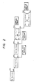
- FIG. 1 a 6-cylinder engine 11 having cylinders 1 to 6 is illustrated. Each cylinder is provided with an injector for fuel injection. The cylinders of the engine 11 are divided into two groups, and the amount of fuel injection and the injection timing of the cylinders 1, 3 and 5 are controlled by a control circuit 12, while those of the cylinders 2, 4 and 6 are controlled by a control circuit 13.
- the ignition system is the same as in the prior art.
- Each control circuit is different from a conventional electronic fuel injection control apparatus only in the following points. The input of a signal from each sensor and contents of calculation are approximately the same as conventional ones.
- Marked difference are that the ouptput torque in one cycle is equivalent to the output of half the cylinders and the timing process for it is therefore different, and that an interface unit for inputting/outputting the information to/from a decision circuit which decides normal/abnormality of the control circuit for controlling the other half cylinders is provided together with an information processing unit in order to prevent the engine from being stopped.
- control circuit 12 controls the cylinders 1, 3 and 5 of odd numbers, while the control circuit 13 controls the cylinders 2, 4 and 6 of even numbers.
- Each control circuit detects the rotational speed of a shaft by a tachometer 16, a measured value 17 of air flow by an air flow meter (not shown), a cooling water temperature 18 by an engine cooling device (not shown), and other pieces of information (not shown) necessary for controlling the rotational frequency of the engine. Synchronization of the control circuits is carried out on the basis of the timing pulses which are synchronous with the rotation of the engine and which are detected by a timing pulse detector 19.
- the normal or abnormality of the control circuits is decided by decision circuits 14 and 15 which are provided in correspondence to the respective control circuits. It is possible to incorporate the decision circuits into the respective control circuits. Each decision circuit fetches the calculated outputs of the control circuits 12 and 13, and judges whether there is a large difference between the calculated outputs of the control circuits 12 and 13. The process of decision is shown in Fig. 2. The fuel injection periods, which are the outputs of the control circuits 12 and 13, are assumed to be T2 and T3, respectively.
- the decision circuit gives information to the driver on which control circuit is decided to be out of order.
- the driver manually cuts out the defective control circuit when he is informed of the defect of the control circuit, thereby stopping the supply of the fuel to the cylinders which are controlled by that control circuit. Simultaneously, he controls the remaining half cylinders by the normal control circuit.
- the manual cut-out is executed merely by designating the defective control circuit and switching in the interior of the car. That is, it is executed by cutting off the outputs of the other control circuit and the decision circuit which have been input to each control circuit by switching. Even if both control circuits are normal, it is possible to practice at driving with half the cylinders by cutting off one of the control circuits.
- each cylinder in this embodiment, it is possible to provide more than two injectors on a manifold and to provide a control circuit on each injector, providing slight modifications for the circuits.
- the driver can find the defective circuit easily, if the driver carries a spare control circuit (a printed circuit board), he can replace the printed circuit board in accordance with the instruction.
Landscapes
- Engineering & Computer Science (AREA)
- General Engineering & Computer Science (AREA)
- Chemical & Material Sciences (AREA)
- Combustion & Propulsion (AREA)
- Mechanical Engineering (AREA)
- Computer Hardware Design (AREA)
- Microelectronics & Electronic Packaging (AREA)
- Electrical Control Of Air Or Fuel Supplied To Internal-Combustion Engine (AREA)
- Combined Controls Of Internal Combustion Engines (AREA)
- Output Control And Ontrol Of Special Type Engine (AREA)
Applications Claiming Priority (2)
| Application Number | Priority Date | Filing Date | Title |
|---|---|---|---|
| JP252723/85 | 1985-11-13 | ||
| JP60252723A JP2511859B2 (ja) | 1985-11-13 | 1985-11-13 | 内燃機関における燃料噴射制御装置 |
Publications (3)
| Publication Number | Publication Date |
|---|---|
| EP0222403A2 true EP0222403A2 (de) | 1987-05-20 |
| EP0222403A3 EP0222403A3 (en) | 1987-10-07 |
| EP0222403B1 EP0222403B1 (de) | 1990-02-07 |
Family
ID=17241366
Family Applications (1)
| Application Number | Title | Priority Date | Filing Date |
|---|---|---|---|
| EP86115793A Expired EP0222403B1 (de) | 1985-11-13 | 1986-11-13 | System zur elektronischen Steuerung der Kraftstoffeinspritzung in einen Brennkraftmotor |
Country Status (4)
| Country | Link |
|---|---|
| US (2) | US4697566A (de) |
| EP (1) | EP0222403B1 (de) |
| JP (1) | JP2511859B2 (de) |
| DE (1) | DE3668946D1 (de) |
Cited By (5)
| Publication number | Priority date | Publication date | Assignee | Title |
|---|---|---|---|---|
| GB2200476B (en) * | 1987-01-29 | 1991-02-06 | British Gas Plc | Monitor system |
| GB2235068A (en) * | 1989-06-05 | 1991-02-20 | Mitsubishi Electric Corp | Industrial robot apparatus |
| GB2238631A (en) * | 1989-08-25 | 1991-06-05 | Mitsubishi Motors Corp | Throttle valve control. |
| FR2710107A1 (fr) * | 1993-09-14 | 1995-03-24 | Peugeot | Procédé de contrôle du fonctionnement d'un moteur à combustion interne et dispositif pour la mise en Óoeuvre d'un tel procédé. |
| EP1069299A1 (de) * | 1999-07-15 | 2001-01-17 | Renault | Einspritzvorrichtung für Brennkraftmaschine |
Families Citing this family (7)
| Publication number | Priority date | Publication date | Assignee | Title |
|---|---|---|---|---|
| JPH04318253A (ja) * | 1991-04-18 | 1992-11-09 | Mitsubishi Heavy Ind Ltd | 多気筒エンジン |
| DE4332098B4 (de) * | 1993-09-22 | 2004-09-30 | Bayerische Motoren Werke Ag | Brennkraftmaschinen-Steuereinrichtung |
| DE19951581B4 (de) * | 1999-10-27 | 2012-04-26 | Robert Bosch Gmbh | Verfahren und Vorrichtung zur Gleichstellung wenigstens zweier Zylinderbänke einer Brennkraftmaschine |
| DE10009779A1 (de) | 2000-03-01 | 2001-09-06 | Bosch Gmbh Robert | Verfahren zur Klopfregelung einer Verbrennungskraftmaschine |
| DE10038974B4 (de) * | 2000-08-10 | 2007-04-19 | Robert Bosch Gmbh | Verfahren zum Betreiben einer Brennkraftmaschine insbesondere eines Kraftfahrzeugs |
| US6588398B1 (en) * | 2001-12-18 | 2003-07-08 | Caterpillar Inc | Automated electronic trim for a fuel injector |
| JP2005315095A (ja) * | 2004-04-27 | 2005-11-10 | Hitachi Ltd | 内燃機関の異常検出システム |
Family Cites Families (16)
| Publication number | Priority date | Publication date | Assignee | Title |
|---|---|---|---|---|
| GB1244925A (en) * | 1968-10-23 | 1971-09-02 | Brevete Et D Etudes S I B E So | Improvements in or relating to fuel feed devices for internal combustion engines |
| USRE29561E (en) * | 1968-11-12 | 1978-03-07 | Lumenition, Ltd. | Fuel injection systems for internal combustion engines |
| US3835825A (en) * | 1969-11-21 | 1974-09-17 | Brico Eng | Internal combustion engines |
| US3606869A (en) * | 1970-05-11 | 1971-09-21 | Gen Motors Corp | Apparatus for electrically synchronizing fuel injection with fuel ignition in an internal combustion engine |
| US4049957A (en) * | 1971-06-23 | 1977-09-20 | Hitachi, Ltd. | Dual computer system |
| US3834361A (en) * | 1972-08-23 | 1974-09-10 | Bendix Corp | Back-up fuel control system |
| JPS5277930A (en) * | 1975-12-25 | 1977-06-30 | Nissan Motor Co Ltd | Air-fuel ratio controller |
| DE2838619A1 (de) * | 1978-09-05 | 1980-03-20 | Bosch Gmbh Robert | Einrichtung zum steuern von betriebsparameterabhaengigen und sich wiederholenden vorgaengen fuer brennkraftmaschinen |
| JPS57173536A (en) * | 1981-04-16 | 1982-10-25 | Nissan Motor Co Ltd | Fuel feed controller of internal combustion engine |
| JPS5810246A (ja) * | 1981-07-13 | 1983-01-20 | Nissan Motor Co Ltd | 車両用ディジタル制御装置 |
| JPS58124028A (ja) * | 1982-01-20 | 1983-07-23 | Nippon Denso Co Ltd | 多気筒内燃機関用燃料噴射制御装置 |
| GB2125578A (en) * | 1982-08-16 | 1984-03-07 | Nissan Motor | Self monitoring system |
| DE3234637A1 (de) * | 1982-09-18 | 1984-03-22 | Alfred Teves Gmbh, 6000 Frankfurt | Verfahren und schaltungsanordnung zur steuerung einer bremsschlupfregelanlage |
| JPS59108847A (ja) * | 1982-12-13 | 1984-06-23 | Japan Electronic Control Syst Co Ltd | エンジン制御装置 |
| JPS59213548A (ja) * | 1983-05-17 | 1984-12-03 | Nissan Motor Co Ltd | 車両用制御システムの故障診断装置 |
| JPS6090942A (ja) * | 1983-10-25 | 1985-05-22 | Mazda Motor Corp | 電子燃料噴射装置 |
-
1985
- 1985-11-13 JP JP60252723A patent/JP2511859B2/ja not_active Expired - Lifetime
-
1986
- 1986-11-07 US US06/927,938 patent/US4697566A/en not_active Ceased
- 1986-11-13 EP EP86115793A patent/EP0222403B1/de not_active Expired
- 1986-11-13 DE DE8686115793T patent/DE3668946D1/de not_active Expired - Lifetime
-
1989
- 1989-10-06 US US07/417,900 patent/USRE33890E/en not_active Expired - Lifetime
Cited By (10)
| Publication number | Priority date | Publication date | Assignee | Title |
|---|---|---|---|---|
| GB2200476B (en) * | 1987-01-29 | 1991-02-06 | British Gas Plc | Monitor system |
| GB2235068A (en) * | 1989-06-05 | 1991-02-20 | Mitsubishi Electric Corp | Industrial robot apparatus |
| US5019762A (en) * | 1989-06-05 | 1991-05-28 | Mitsubishi Denki Kabushiki Kaisha | Industrial robot apparatus |
| GB2235068B (en) * | 1989-06-05 | 1993-07-28 | Mitsubishi Electric Corp | Industrial robot apparatus |
| GB2238631A (en) * | 1989-08-25 | 1991-06-05 | Mitsubishi Motors Corp | Throttle valve control. |
| GB2238631B (en) * | 1989-08-25 | 1994-03-30 | Mitsubishi Motors Corp | Throttle valve control apparatus |
| FR2710107A1 (fr) * | 1993-09-14 | 1995-03-24 | Peugeot | Procédé de contrôle du fonctionnement d'un moteur à combustion interne et dispositif pour la mise en Óoeuvre d'un tel procédé. |
| EP0652359A1 (de) * | 1993-09-14 | 1995-05-10 | Automobiles Peugeot | Verfahren zur Steuerung des Betriebs einer Brennkraftmaschine und Vorrichtung zur Durchführen eines derartigen Verfahrens |
| EP1069299A1 (de) * | 1999-07-15 | 2001-01-17 | Renault | Einspritzvorrichtung für Brennkraftmaschine |
| FR2796420A1 (fr) * | 1999-07-15 | 2001-01-19 | Renault | Dispositif d'injection pour moteur a combustion interne |
Also Published As
| Publication number | Publication date |
|---|---|
| USRE33890E (en) | 1992-04-21 |
| DE3668946D1 (de) | 1990-03-15 |
| JPS62113838A (ja) | 1987-05-25 |
| US4697566A (en) | 1987-10-06 |
| JP2511859B2 (ja) | 1996-07-03 |
| EP0222403B1 (de) | 1990-02-07 |
| EP0222403A3 (en) | 1987-10-07 |
Similar Documents
| Publication | Publication Date | Title |
|---|---|---|
| US4697566A (en) | Method of controlling electronic fuel injection to internal combustion engine | |
| JP2625148B2 (ja) | 車載電子制御装置 | |
| US4527424A (en) | System for diagnosing an internal combustion engine | |
| GB2216288A (en) | Diagnostic system for the electronic control system of an automotive engine | |
| US20060200301A1 (en) | Engine control method and device | |
| JPS60132041A (ja) | 燃料供給装置用非常制御装置 | |
| KR100192423B1 (ko) | 액츄에이터의 고장판단 제어 방법 | |
| JPH05273086A (ja) | 少なくとも1つのマイクロコンピュータを有する装置をテストする装置並びに方法 | |
| EP0291126B1 (de) | Kontrolleinheit für die Anzeigelampen am Armaturenbrett eines Fahrzeuges | |
| KR19980039774U (ko) | 자동차의 고장진단 메시지 표시장치 | |
| KR100253788B1 (ko) | 크랭크각 센서 고장에 따른 전자제어방법 | |
| KR100204155B1 (ko) | 맵 센서의 모니터링 방법 | |
| JP2000073841A (ja) | 内燃機関の警告灯故障診断装置、方法及び故障時制御方法 | |
| JP2936570B2 (ja) | 自動車用故障表示装置 | |
| JP2625018B2 (ja) | 電子制御エンジン制御方法 | |
| KR0180396B1 (ko) | 엔진의 고장 경고등을 이용한 고장코드 생성방법 | |
| KR970002175Y1 (ko) | 자동차의 결함상태 자동 디스플레이 장치 | |
| JPS6397855A (ja) | 内燃機関用制御装置 | |
| JPS595310A (ja) | 車両故障診断装置 | |
| KR100197107B1 (ko) | 출력 액츄에이터 자기진단시 진단오류 방지방법 | |
| JP2002106410A (ja) | 内燃機関の構成要素の診断方法、コンピュータプログラムおよび装置 | |
| JPS6189956A (ja) | 電子制御式燃料噴射装置 | |
| DE3335631A1 (de) | Anordnung zur diagnose eines verbrennungsmotors | |
| JPS58158346A (ja) | 内燃機関の制御装置の故障検出方法 | |
| KR20000014029A (ko) | 전자제어식 디젤엔진의 솔레노이드 밸브의 고장진단 방법 |
Legal Events
| Date | Code | Title | Description |
|---|---|---|---|
| PUAI | Public reference made under article 153(3) epc to a published international application that has entered the european phase |
Free format text: ORIGINAL CODE: 0009012 |
|
| AK | Designated contracting states |
Kind code of ref document: A2 Designated state(s): DE GB |
|
| PUAL | Search report despatched |
Free format text: ORIGINAL CODE: 0009013 |
|
| AK | Designated contracting states |
Kind code of ref document: A3 Designated state(s): DE GB |
|
| 17P | Request for examination filed |
Effective date: 19871008 |
|
| 17Q | First examination report despatched |
Effective date: 19880217 |
|
| GRAA | (expected) grant |
Free format text: ORIGINAL CODE: 0009210 |
|
| AK | Designated contracting states |
Kind code of ref document: B1 Designated state(s): DE GB |
|
| REF | Corresponds to: |
Ref document number: 3668946 Country of ref document: DE Date of ref document: 19900315 |
|
| PLBE | No opposition filed within time limit |
Free format text: ORIGINAL CODE: 0009261 |
|
| STAA | Information on the status of an ep patent application or granted ep patent |
Free format text: STATUS: NO OPPOSITION FILED WITHIN TIME LIMIT |
|
| 26N | No opposition filed | ||
| PGFP | Annual fee paid to national office [announced via postgrant information from national office to epo] |
Ref country code: GB Payment date: 19931103 Year of fee payment: 8 |
|
| PG25 | Lapsed in a contracting state [announced via postgrant information from national office to epo] |
Ref country code: GB Effective date: 19941113 |
|
| GBPC | Gb: european patent ceased through non-payment of renewal fee |
Effective date: 19941113 |
|
| PGFP | Annual fee paid to national office [announced via postgrant information from national office to epo] |
Ref country code: DE Payment date: 20031203 Year of fee payment: 18 |
|
| PG25 | Lapsed in a contracting state [announced via postgrant information from national office to epo] |
Ref country code: DE Free format text: LAPSE BECAUSE OF NON-PAYMENT OF DUE FEES Effective date: 20050601 |