EP0216724B1 - Antriebsvorrichtung für einen Leistungsschalter mit einem Klinkenrad - Google Patents
Antriebsvorrichtung für einen Leistungsschalter mit einem Klinkenrad Download PDFInfo
- Publication number
- EP0216724B1 EP0216724B1 EP86730132A EP86730132A EP0216724B1 EP 0216724 B1 EP0216724 B1 EP 0216724B1 EP 86730132 A EP86730132 A EP 86730132A EP 86730132 A EP86730132 A EP 86730132A EP 0216724 B1 EP0216724 B1 EP 0216724B1
- Authority
- EP
- European Patent Office
- Prior art keywords
- ratchet wheel
- lever
- centrifugal force
- rotation
- energy store
- Prior art date
- Legal status (The legal status is an assumption and is not a legal conclusion. Google has not performed a legal analysis and makes no representation as to the accuracy of the status listed.)
- Expired - Lifetime
Links
Images

Classifications
-
- F—MECHANICAL ENGINEERING; LIGHTING; HEATING; WEAPONS; BLASTING
- F16—ENGINEERING ELEMENTS AND UNITS; GENERAL MEASURES FOR PRODUCING AND MAINTAINING EFFECTIVE FUNCTIONING OF MACHINES OR INSTALLATIONS; THERMAL INSULATION IN GENERAL
- F16H—GEARING
- F16H31/00—Other gearings with freewheeling members or other intermittently driving members
-
- H—ELECTRICITY
- H01—ELECTRIC ELEMENTS
- H01H—ELECTRIC SWITCHES; RELAYS; SELECTORS; EMERGENCY PROTECTIVE DEVICES
- H01H3/00—Mechanisms for operating contacts
- H01H3/22—Power arrangements internal to the switch for operating the driving mechanism
- H01H3/30—Power arrangements internal to the switch for operating the driving mechanism using spring motor
- H01H3/3005—Charging means
- H01H3/3021—Charging means using unidirectional coupling
-
- Y—GENERAL TAGGING OF NEW TECHNOLOGICAL DEVELOPMENTS; GENERAL TAGGING OF CROSS-SECTIONAL TECHNOLOGIES SPANNING OVER SEVERAL SECTIONS OF THE IPC; TECHNICAL SUBJECTS COVERED BY FORMER USPC CROSS-REFERENCE ART COLLECTIONS [XRACs] AND DIGESTS
- Y10—TECHNICAL SUBJECTS COVERED BY FORMER USPC
- Y10T—TECHNICAL SUBJECTS COVERED BY FORMER US CLASSIFICATION
- Y10T74/00—Machine element or mechanism
- Y10T74/11—Tripping mechanism
-
- Y—GENERAL TAGGING OF NEW TECHNOLOGICAL DEVELOPMENTS; GENERAL TAGGING OF CROSS-SECTIONAL TECHNOLOGIES SPANNING OVER SEVERAL SECTIONS OF THE IPC; TECHNICAL SUBJECTS COVERED BY FORMER USPC CROSS-REFERENCE ART COLLECTIONS [XRACs] AND DIGESTS
- Y10—TECHNICAL SUBJECTS COVERED BY FORMER USPC
- Y10T—TECHNICAL SUBJECTS COVERED BY FORMER US CLASSIFICATION
- Y10T74/00—Machine element or mechanism
- Y10T74/15—Intermittent grip type mechanical movement
- Y10T74/1558—Grip units and features
- Y10T74/1565—Gripper releasing devices
- Y10T74/1566—Power pawl lifter
- Y10T74/1568—Automatic
Definitions
- the invention relates to a drive device for a circuit breaker with a ratchet wheel for tensioning an energy store by gradually rotating the ratchet wheel by means of a transport pawl, and with a coupling means for automatically lifting the transport pawl from the toothing of the ratchet wheel as it rotates in the course of relaxation of the energy store by means of an arc outer work surface.
- a drive device of this kind is known from GB-A-799 665.
- the device for lifting the transport pawl has the task of avoiding damage that can occur during the very rapid rotation of the ratchet wheel associated with the relaxation of the energy store, both on its toothing and on the transport pawl. Damages of this type limit the life of the drive device and must therefore be kept so low that the number of switching operations provided in practice can be carried out.
- a protective body mounted on the axis of the ratchet wheel serves as coupling means, which is inserted between the pawls and the teeth of the ratchet wheel by a lever linkage when the energy store is released.
- the lever linkage sits on the pivot axis of the ratchet lever, which controls the release of the energy store.
- the invention is based on a drive device of the type mentioned, the task of making the device for lifting the transport pawl so simple that an increase in the drive device by a lever linkage and other parts avoided as far as possible and separate means for resetting the coupling means are not required .
- a coupling means a radially pivotable on the ratchet wheel and at a distance from the axis of rotation of the ratchet wheel, which is provided on the outside with the working surface, is provided in the form of a centrifugal lever and that under the influence of the centrifugal force radial movement of the centrifugal force lever is limited by a stop.
- the clutch means are thus actuated by the rotation of the ratchet wheel due to the centrifugal force that occurs. As soon as the ratchet wheel comes to rest, the centrifugal force disappears and the pawls can engage in the toothing again.
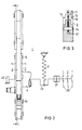
- Figures 1 and 2 show part of a drive device of a low-voltage circuit breaker in two mutually perpendicular, partially sectioned views. 1 is section I-I in FIG. 2.
- FIG. 3 shows as section III-III in FIG. 1 a detail in the area of a ratchet wheel of the drive device according to FIGS. 1 and 2, partly in section.
- the figures show the essential parts of a drive device for a low-voltage circuit breaker.
- the drive device designated as a whole by 1 acts as a storage drive and for this purpose has a tension spring 2 as an energy store.
- a tension spring 2 as an energy store.
- two or more tension springs or a corresponding arrangement of compression springs or another energy store to be tensioned by a mechanical movement can also be provided.
- a ratchet wheel 3 is used to tension the tension spring 2 and is fastened on a shaft 4 (FIG. 2) which is mounted in suitable but not shown bearings.
- the ratchet wheel 3 is provided with teeth 5 which are arranged on the circumference of the ratchet wheel 3 in a uniform division. About half the circumference of the ratchet wheel 3 is designed without teeth. The purpose of this design will be explained later.
- a transport pawl 6 interacts with the teeth 5 of the ratchet wheel 3 and is arranged in a rotatably mounted cage 7 so as to be pivotable about a bearing pin 10.
- the cage 7 consists of two plates 11 which are held at a suitable distance by connecting elements 12 and are rigidly connected. With circular cutouts 13 of the plates 11, the cage 7 is mounted on the ratchet wheel 3, which for this purpose has paragraphs 14 on both sides of the toothing.
- a spiral spring 15 provides a pressing force by means of which the transport pawl 6 is held in engagement with the teeth 5.
- the cage 7 is connected in an articulated manner to an angle lever 16 which can be pivoted about a fixed bearing 17 and which can be driven back and forth at its free end in accordance with the double arrow 20.
- a motor with a gear and an eccentric can be provided in a known manner.
- the periodic pivoting movement of the angle lever 16 is transmitted to the cage 7 by a coupling rod 21 and is thereby converted into a periodic angular rotation.
- a backstop 22 (FIG. 2), which can be a directional lock with a ratchet wheel similar to the ratchet wheel 3 or a pinch roller freewheel in a known manner, the ratchet wheel 3 is gradually advanced by the periodic pivoting movement of the angle lever 16.
- the tension spring 2 is tensioned by means of a crank pin 23 shown schematically in FIGS. 1 and 2 until the dead center position with respect to the force application of the tension spring 2 to the crank pin 23 is reached and the crank pin comes to rest against a pawl 24 shortly after the dead center is exceeded ( Figure 1).
- a limit switch By means known per se, e.g. B. a limit switch, the drive motor is then stopped, which causes the periodic pivoting movement of the angle lever 16.
- a suitable auxiliary drive e.g. B. the electromagnet 25 shown in FIG. 2, which actuates the pawl 24 and thereby releases the crank pin 23.
- the switching contacts 26 of the circuit breaker which are also shown schematically, are then switched on via a switching lock 27.
- the relaxation of the tension spring 2 when switching on is associated with an extremely rapid rotation of the ratchet wheel 3.
- Premature wear of the interacting parts is avoided by a centrifugal lever 30 which is arranged in the ratchet wheel 3.
- the centrifugal lever 30 has an outer circular working surface 31 as a coupling means and is pivotally mounted at its front end 33 in the direction of rotation of the ratchet wheel 3 (arrow 32) on a bolt 34 arranged at a distance from the axis of rotation of the ratchet wheel. It thus acts as a one-armed lever.
- the centrifugal lever 30 Near its rear end, seen in the direction of rotation of the ratchet wheel, the centrifugal lever 30 has an elongated hole 35 for a stop pin 36 attached to the ratchet wheel 3, which limits the pivoting movement of the centrifugal lever 30 to the outside.
- the centrifugal lever 30 has a contour on its inside which roughly corresponds to an arc, insofar as the arrangement of the bearing pin 34, the stop pin 36 and the required strength allow this.
- a recess 37 of relatively small depth is therefore sufficient, which in the example shown is formed by two straight incisions with the edges 40 and 41.
- the radial recess 37 is located in the center of the ratchet wheel 3, as shown in Figure 3.
- the toothing of the ratchet wheel 3 extends only over approximately half the circumference of the ratchet wheel.
- the ratchet wheel 3 In the position shown in Figure 1 the ratchet wheel 3 is located near the dead center position of the crank pin 23, since only three teeth 5 have to be covered up to the tooth-free area 42.
- the tooth-free area 42 can be provided if only one transport pawl 6 is required and the ratchet wheel is not required for the engagement of a further pawl as a backstop.
- a separate backstop 22 (FIG. 2) is provided.
- the transport pawl 6 When the tension spring 2 is released, the transport pawl 6 initially slides essentially without wear on the tooth-free area 42 of the ratchet wheel 3. In the further course of motion, however, the ratchet wheel 3 does not come to a standstill with the end part 43 of the tooth-free area 42 at the transport pawl 6, but instead turns on. The extent to which this happens depends on how large the energy surplus is; for example, the further rotation of the ratchet wheel 3 turns out to be relatively small if the switch contacts 26 are switched on under heavy load, while relaxation of the tension spring 2 with the switch contacts 26 already switched on leads to a considerably greater rotation of the ratchet wheel 3. Accordingly, the transport pawl 6 passes through a more or less large part of the toothing of the ratchet wheel 3.
- the centrifugal lever 30 is pushed outwards as a result of the rapid rotation of the ratchet wheel 3, so that now the transport pawl 6 slides on the working surface 31 of the centrifugal lever 30 protruding from the teeth 5.
- the spiral spring 15 is dimensioned such that it can overcome the resistance to movement of the centrifugal force lever 30.
- the working surface 31 of the centrifugal lever 30 covers an angle of approximately 120 ° and thus the area which is maximally passed through when the tension spring 2 is relaxed. If a ratchet wheel with a larger toothed part of the circumference or a ratchet wheel toothed over the entire circumference is used, undesired wear of the transport pawl or further pawls engaged with the toothing can be avoided by a further one or more centrifugal levers, which basically correspond to the same Way as the centrifugal lever 30 are formed and attached to the ratchet wheel 3.
Landscapes
- Engineering & Computer Science (AREA)
- General Engineering & Computer Science (AREA)
- Mechanical Engineering (AREA)
- Transmission Devices (AREA)
- Driving Mechanisms And Operating Circuits Of Arc-Extinguishing High-Tension Switches (AREA)
Applications Claiming Priority (2)
| Application Number | Priority Date | Filing Date | Title |
|---|---|---|---|
| DE19853533179 DE3533179A1 (de) | 1985-09-13 | 1985-09-13 | Antriebsvorrichtung fuer einen leistungsschalter mit einem klinkenrad |
| DE3533179 | 1985-09-13 |
Publications (2)
| Publication Number | Publication Date |
|---|---|
| EP0216724A1 EP0216724A1 (de) | 1987-04-01 |
| EP0216724B1 true EP0216724B1 (de) | 1991-06-12 |
Family
ID=6281211
Family Applications (1)
| Application Number | Title | Priority Date | Filing Date |
|---|---|---|---|
| EP86730132A Expired - Lifetime EP0216724B1 (de) | 1985-09-13 | 1986-09-05 | Antriebsvorrichtung für einen Leistungsschalter mit einem Klinkenrad |
Country Status (4)
| Country | Link |
|---|---|
| US (1) | US4750375A (ja) |
| EP (1) | EP0216724B1 (ja) |
| JP (1) | JPH0721982B2 (ja) |
| DE (2) | DE3533179A1 (ja) |
Families Citing this family (8)
| Publication number | Priority date | Publication date | Assignee | Title |
|---|---|---|---|---|
| DE3737686A1 (de) * | 1987-11-06 | 1989-05-18 | Teldix Gmbh | Elektromechanische vorrichtung zum arretieren einer welle in wenigstens einer stellung |
| US5004875A (en) * | 1988-10-11 | 1991-04-02 | Siemens Energy & Automation, Inc. | Stored energy contact operating mechanism |
| US4899022A (en) * | 1988-10-11 | 1990-02-06 | Siemens Energy & Automation, Inc. | Stored energy operating mechanism charging handle and cover assembly |
| DE4034126C1 (ja) * | 1990-10-26 | 1992-03-05 | Maschinenfabrik Reinhausen Gmbh, 8400 Regensburg, De | |
| US5224590A (en) * | 1991-11-06 | 1993-07-06 | Westinghouse Electric Corp. | Circuit interrupter having improved operating mechanism |
| DE4337344B4 (de) * | 1993-11-02 | 2005-08-25 | Moeller Gmbh | Strombegrenzendes Kontaktsystem für Leistungsschalter |
| DE102006006907A1 (de) * | 2006-02-09 | 2007-08-16 | Siemens Ag | Anordnung insbesondere zum Betätigen einer Transportklinke und Spannvorrichtung für einen Federspeicher eines elektrischen Schalters mit einer derartigen Anordnung |
| US9534730B2 (en) | 2010-08-26 | 2017-01-03 | Garrett W. Brown | Multi-arm gimbal system |
Family Cites Families (13)
| Publication number | Priority date | Publication date | Assignee | Title |
|---|---|---|---|---|
| US2417602A (en) * | 1945-09-04 | 1947-03-18 | Ryan Aeronautical Co | Ratchet means |
| GB799665A (en) * | 1954-09-10 | 1958-08-13 | English Electric Co Ltd | Improvements in and relating to escapement devices |
| FR1347857A (fr) * | 1962-11-21 | 1964-01-04 | Merlin Gerin | Dispositif de commande à accumulation d'énergie, notamment pour disjoncteurs |
| US3689720A (en) * | 1971-09-16 | 1972-09-05 | Westinghouse Electric Corp | Circuit breaker including spring closing means with means for moving a charging pawl out of engagement with a ratchet wheel when the spring means are charged |
| US3791231A (en) * | 1972-04-03 | 1974-02-12 | Carrier Corp | Turbine turning mechanism |
| US4153828A (en) * | 1976-07-08 | 1979-05-08 | General Electric Company | Stored-energy operating means for an electric circuit breaker |
| US4095676A (en) * | 1976-11-23 | 1978-06-20 | Howe-Yin Research Co., Inc. | Stored energy operation for breakers |
| US4167988A (en) * | 1978-06-20 | 1979-09-18 | General Electric Company | Ratcheting mechanism for circuit breaker motor operator |
| JPS58184227A (ja) * | 1982-04-20 | 1983-10-27 | 三菱電機株式会社 | 回路しや断器の電動ばね操作機構 |
| JPS58184228A (ja) * | 1982-04-20 | 1983-10-27 | 三菱電機株式会社 | 回路しや断器の電動ばね操作機構 |
| JPS5912515A (ja) * | 1982-07-12 | 1984-01-23 | 三菱電機株式会社 | 開閉器のばね操作装置 |
| JPS5912514A (ja) * | 1982-07-12 | 1984-01-23 | 三菱電機株式会社 | 開閉器のばね操作装置 |
| JPS59189519A (ja) * | 1983-04-12 | 1984-10-27 | 富士電機株式会社 | しや断器操作用蓄勢器の駆動装置 |
-
1985
- 1985-09-13 DE DE19853533179 patent/DE3533179A1/de not_active Withdrawn
-
1986
- 1986-09-03 US US06/903,397 patent/US4750375A/en not_active Expired - Fee Related
- 1986-09-05 EP EP86730132A patent/EP0216724B1/de not_active Expired - Lifetime
- 1986-09-05 DE DE8686730132T patent/DE3679752D1/de not_active Expired - Fee Related
- 1986-09-09 JP JP61212520A patent/JPH0721982B2/ja not_active Expired - Lifetime
Also Published As
| Publication number | Publication date |
|---|---|
| DE3679752D1 (de) | 1991-07-18 |
| EP0216724A1 (de) | 1987-04-01 |
| JPH0721982B2 (ja) | 1995-03-08 |
| JPS6266519A (ja) | 1987-03-26 |
| US4750375A (en) | 1988-06-14 |
| DE3533179A1 (de) | 1987-03-19 |
Similar Documents
| Publication | Publication Date | Title |
|---|---|---|
| DE3118710C2 (ja) | ||
| EP0463990B1 (de) | Elektrisch betriebenes Austraggerät | |
| EP0999132B1 (de) | Umreifungsgerät | |
| DE2928592A1 (de) | Klinkenschloss fuer spanngurte | |
| DE19901453B4 (de) | Trimmaschine mit einer Bremseinrichtung für das Schneidblatt | |
| DE2401385C3 (ja) | ||
| EP0216724B1 (de) | Antriebsvorrichtung für einen Leistungsschalter mit einem Klinkenrad | |
| DE19642031A1 (de) | Betätigungseinrichtung eines Trennschalters | |
| DE2621812C2 (de) | Sicherheitsbremse zum Abbremsen der Sägekette bei einer tragbaren Motorkettensäge | |
| DE2620036C3 (de) | Abstreifeinrichtung für Förderbänder | |
| EP0174906B1 (de) | Antriebsvorrichtung für einen Leistungsschalter mit Exzenter und Richtgesperre | |
| DE3005968C2 (de) | Fadenschneider | |
| DE2439837C3 (de) | Antriebsvorrichtung zur Sprungbetätigung elektrischer Schaltgeräte | |
| DE4136684C2 (de) | Köderangelrolle | |
| DE2700929C3 (de) | Vorrichtung zum mechanischen Verbinden eines Stellantriebes mit einem zu verstellenden Element | |
| DE163173C (ja) | ||
| DE2726581A1 (de) | Aufwickel- und abwickelvorrichtung, insbesondere fuer riemen von sicherheitsgurten | |
| DE4304544A1 (de) | Antriebseinrichtung für einen elektrischen Leistungsschalter | |
| DE8113008U1 (de) | Vorrichtung fuer farbbaender in schreibmaschinen oder aehnlichen geraeten | |
| DE1505681C3 (ja) | ||
| AT239476B (de) | Hubfahrwerk | |
| DE669104C (de) | Verschiebevorrichtung an Werkzeugmaschinen, insbesondere fuer den Ausleger an Radialbrmaschinen | |
| DE2057804C3 (de) | Einrichtung zum Aufstellen von Kegeln in einer Kegelbahnanlage | |
| DE1810136C (de) | Mechanische Schalteinrichtung fur ein Planeten Wendegetriebe mit einer Kupp lung und einer Bremse | |
| DE2009057C (de) | Einstellvorrichtung fur einen Typen raddrucker |
Legal Events
| Date | Code | Title | Description |
|---|---|---|---|
| PUAI | Public reference made under article 153(3) epc to a published international application that has entered the european phase |
Free format text: ORIGINAL CODE: 0009012 |
|
| AK | Designated contracting states |
Kind code of ref document: A1 Designated state(s): DE FR GB IT SE |
|
| 17P | Request for examination filed |
Effective date: 19870925 |
|
| 17Q | First examination report despatched |
Effective date: 19890921 |
|
| GRAA | (expected) grant |
Free format text: ORIGINAL CODE: 0009210 |
|
| AK | Designated contracting states |
Kind code of ref document: B1 Designated state(s): DE FR GB IT SE |
|
| REF | Corresponds to: |
Ref document number: 3679752 Country of ref document: DE Date of ref document: 19910718 |
|
| ET | Fr: translation filed | ||
| ITF | It: translation for a ep patent filed |
Owner name: STUDIO JAUMANN |
|
| GBT | Gb: translation of ep patent filed (gb section 77(6)(a)/1977) | ||
| PLBE | No opposition filed within time limit |
Free format text: ORIGINAL CODE: 0009261 |
|
| STAA | Information on the status of an ep patent application or granted ep patent |
Free format text: STATUS: NO OPPOSITION FILED WITHIN TIME LIMIT |
|
| 26N | No opposition filed | ||
| EAL | Se: european patent in force in sweden |
Ref document number: 86730132.7 |
|
| PGFP | Annual fee paid to national office [announced via postgrant information from national office to epo] |
Ref country code: GB Payment date: 19950821 Year of fee payment: 10 |
|
| PGFP | Annual fee paid to national office [announced via postgrant information from national office to epo] |
Ref country code: SE Payment date: 19950912 Year of fee payment: 10 |
|
| PG25 | Lapsed in a contracting state [announced via postgrant information from national office to epo] |
Ref country code: GB Effective date: 19960905 |
|
| PG25 | Lapsed in a contracting state [announced via postgrant information from national office to epo] |
Ref country code: SE Effective date: 19960906 |
|
| GBPC | Gb: european patent ceased through non-payment of renewal fee |
Effective date: 19960905 |
|
| EUG | Se: european patent has lapsed |
Ref document number: 86730132.7 |
|
| PGFP | Annual fee paid to national office [announced via postgrant information from national office to epo] |
Ref country code: DE Payment date: 20001120 Year of fee payment: 15 |
|
| PGFP | Annual fee paid to national office [announced via postgrant information from national office to epo] |
Ref country code: FR Payment date: 20010928 Year of fee payment: 16 |
|
| PG25 | Lapsed in a contracting state [announced via postgrant information from national office to epo] |
Ref country code: DE Free format text: LAPSE BECAUSE OF NON-PAYMENT OF DUE FEES Effective date: 20020501 |
|
| PG25 | Lapsed in a contracting state [announced via postgrant information from national office to epo] |
Ref country code: FR Free format text: LAPSE BECAUSE OF NON-PAYMENT OF DUE FEES Effective date: 20030603 |
|
| REG | Reference to a national code |
Ref country code: FR Ref legal event code: ST |
|
| PG25 | Lapsed in a contracting state [announced via postgrant information from national office to epo] |
Ref country code: IT Free format text: LAPSE BECAUSE OF NON-PAYMENT OF DUE FEES;WARNING: LAPSES OF ITALIAN PATENTS WITH EFFECTIVE DATE BEFORE 2007 MAY HAVE OCCURRED AT ANY TIME BEFORE 2007. THE CORRECT EFFECTIVE DATE MAY BE DIFFERENT FROM THE ONE RECORDED. Effective date: 20050905 |