EP0212406A2 - Gerät zur absoluten Linearlageerkennung - Google Patents
Gerät zur absoluten Linearlageerkennung Download PDFInfo
- Publication number
- EP0212406A2 EP0212406A2 EP86110717A EP86110717A EP0212406A2 EP 0212406 A2 EP0212406 A2 EP 0212406A2 EP 86110717 A EP86110717 A EP 86110717A EP 86110717 A EP86110717 A EP 86110717A EP 0212406 A2 EP0212406 A2 EP 0212406A2
- Authority
- EP
- European Patent Office
- Prior art keywords
- pattern
- patterns
- absolute position
- detection device
- detection head
- Prior art date
- Legal status (The legal status is an assumption and is not a legal conclusion. Google has not performed a legal analysis and makes no representation as to the accuracy of the status listed.)
- Granted
Links
Images


Classifications
-
- F—MECHANICAL ENGINEERING; LIGHTING; HEATING; WEAPONS; BLASTING
- F15—FLUID-PRESSURE ACTUATORS; HYDRAULICS OR PNEUMATICS IN GENERAL
- F15B—SYSTEMS ACTING BY MEANS OF FLUIDS IN GENERAL; FLUID-PRESSURE ACTUATORS, e.g. SERVOMOTORS; DETAILS OF FLUID-PRESSURE SYSTEMS, NOT OTHERWISE PROVIDED FOR
- F15B15/00—Fluid-actuated devices for displacing a member from one position to another; Gearing associated therewith
- F15B15/20—Other details, e.g. assembly with regulating devices
- F15B15/28—Means for indicating the position, e.g. end of stroke
- F15B15/2815—Position sensing, i.e. means for continuous measurement of position, e.g. LVDT
- F15B15/2861—Position sensing, i.e. means for continuous measurement of position, e.g. LVDT using magnetic means
-
- F—MECHANICAL ENGINEERING; LIGHTING; HEATING; WEAPONS; BLASTING
- F15—FLUID-PRESSURE ACTUATORS; HYDRAULICS OR PNEUMATICS IN GENERAL
- F15B—SYSTEMS ACTING BY MEANS OF FLUIDS IN GENERAL; FLUID-PRESSURE ACTUATORS, e.g. SERVOMOTORS; DETAILS OF FLUID-PRESSURE SYSTEMS, NOT OTHERWISE PROVIDED FOR
- F15B15/00—Fluid-actuated devices for displacing a member from one position to another; Gearing associated therewith
- F15B15/20—Other details, e.g. assembly with regulating devices
- F15B15/28—Means for indicating the position, e.g. end of stroke
- F15B15/2815—Position sensing, i.e. means for continuous measurement of position, e.g. LVDT
- F15B15/2846—Position sensing, i.e. means for continuous measurement of position, e.g. LVDT using detection of markings, e.g. markings on the piston rod
-
- H—ELECTRICITY
- H03—ELECTRONIC CIRCUITRY
- H03M—CODING; DECODING; CODE CONVERSION IN GENERAL
- H03M1/00—Analogue/digital conversion; Digital/analogue conversion
- H03M1/12—Analogue/digital converters
- H03M1/22—Analogue/digital converters pattern-reading type
- H03M1/24—Analogue/digital converters pattern-reading type using relatively movable reader and disc or strip
- H03M1/28—Analogue/digital converters pattern-reading type using relatively movable reader and disc or strip with non-weighted coding
- H03M1/287—Analogue/digital converters pattern-reading type using relatively movable reader and disc or strip with non-weighted coding using gradually changing slit width or pitch within one track; using plural tracks having slightly different pitches, e.g. of the Vernier or nonius type
Definitions
- This invention relates to an absolute linear position detection device used for a positioning device or the like and, particularly, to a position detection device realizing an enlarged detection range within which a position can be detected in an absolute value with a simplified construction.
- Japanese Preliminary Utility Model Publication No. 136718/1983 filed by the applicant of the present application discloses a detection device in which a magnetic substance portion and a non-magnetic substance portion are alternately and repeatedly provided on a rod section in the logitudinal direction thereof, a magnetic type detection head (detection sensor) comprising a primary coil and a secondary coil is provided in proximity to this rod section, the rod section is relatively displaced with respect to the sensor in accobrdance with mechanical linear displacement which is the object of detection, and an output signal corresponding to absolute position of the rod section relative to the seonsor is derived from the sensor.
- This prior art device however, has the problem that the range within which the position can be detected in an absolute value is limited to the length of one pitch of repetition of the magnetic substance portion and the non-magnetic portion.
- US Patent 4,572,951 discloses a device in which a plurality of rod sections are provided, the pitch of repetition of a magnetic substance portion and a non-magnetic portion is made different from one rod section to another and detection of position over a wide range is realized by processing absolute position detection data concerning respective rod sections.
- an object of the invention to provide an absolute position detection device which is capable of expanding the range within which the absolute position can be detected without providing a plurality of rod sections.
- the absolute position detection device is characterized in that it comprises a member having a first pattern which repeats change in the longitudinal direction of the member with a predetermined pitch and a second pattern which changes in the longitudinal direction of the member with a pitch which is different at least from that of the first pattern, these patterns being formed of a predetermined material and disposed on the member, and a detection head section provided in proximity to this member and responding individually to the first pattern and the second pattern on said member, said detection head section changing its relation of correspondence to the respective patterns in accordance with its linear position with respect to said member and producing output signals in accordance with the relation of correspondence to the respective patterns.
- this member Since plural patterns of different pitches are both provided on a common member, the structure of this member can be simplified. If, for example, this member is a rod, it is no longer necessary to provide a rod for each pattern since plural patterns can be provided commonly on a single rod and, accordingly, the structure of the rod member can be simplified.
- the second pattern may consist of a pattern which is of a different form from the first pattern.
- the two patterns can be disposed in a mixed state in a common region of the member.
- the second pattern may consist of a pattern which is of substantially the same form as the first pattern.
- the respective patterns may be independently disposed along different channels provided on the member.
- the detection head section comprises a plurality of detection heads producing output signals individually in correspondence to the respective patterns.
- it comprises a first detection head which changes its relation of correspondence to the first pattern in accordance with its positional relation with respect to the member on which the patterns are provided and produces an output signal corresponding to this relation of correspondence and a second detection head which changes its relation of correspondence to the second pattern in accordance with its positional relation with respect to the member and produces an output signal corresponding to this relation of correspondence.
- the detection head section may consist of a detection head which is common to the respective patterns. A plurality of output signals corresponding to the respective patterns may be individually derived from this common detection head.
- the detection head section may comprise a circuit which electrically processes output signals of this common detection head to provide a plurality of output signals corresponding to the respective patterns.
- a head output signal responsive substantially to the first pattern only and a head output signal responsive substantilly to the second pattern only may be separately obtained.
- position data corresponding to the relative positional relation between the member on which the patterns are provided and the detection head section can be obtained as data having periodicity with one pitch of the first pattern constituting one cycle.
- position data corresponding to the relative positional relation between the member on which the patterns are provided and the detection head section can be obtained as data having periodicity with one pitch of the second pattern constituting one cycle.
- a magnetic type sensor may be employed as the detection head and a material responding to magnetism may be utilized as the material constituting the patterns.
- the patterns may be formed of a good conductor such as copper or aluminum. In this case, an eddy current is produced in response to flux in accordance with the relation of correspondence between the patterns and the head and an output signal corresponding to reluctance change responsive to the eddy current loss can be provided by the detection head.
- the patterns may be formed of magnetic substance such as iron. In this case, reluctance changes in accordance with the relation of correspondence between the patterns and the head and an output signal responsive thereto can be provided by the detection head.
- the magnetic type detection head one comprising means for generating flux and means for detecting magnetism may be employed.
- the means for generating flux comprises a primay exciting coil and the means for detecting magnetism comprises a secondary induction coil.
- the primary coil and the secondary coil may consist of separate coils or may be constructed of a common coil.
- One of the two systems is the vernier system using combination of a main scale and a vernier.
- the vernier system the combination of one of the patterns and the detection head is used as the main scale whereas the combination of the other pattern and the detection head is used as the vernier. Expansion of the range within which the absolute position can be detected is ensured by the main scale and higher resolution of detection is ensured by the vernier.
- relation between one pitch length P of the first pattern and one pitch length L of the second pattern is L » P and one pitch length P of the first pattern is the absolute position detectable range of the vernier and one pitch length L of the second pattern is the absolute position detectable range of the main scale.
- the range in which the second pattern is actually disposed need not be the entire one pitch length L but may be a range which is shorter than L but is longer than P or, conversely, exceed one pitch length L.
- the other system is the absolute position detection system as described in the above mentioned US Patent 4,572,951.
- pitch length P1 of the first pattern and pitch length P2 of the second pattern may be made different from each other and the absolute position detection over a range of plural pitches is realized by carrying out the prescribed operation utilizing detecteion head output signals corresponding to the respective patterns.
- the forms of the respective patterns are determined in relation to the manner of arrangement of the detection heads.
- the forms of the respective patterns can be determined in such a manner that the respective detection heads substantially respond only to their corresponding patterns.
- one of the first and second detection heads is preferably arranged so that it detects the pattern, in a position in which it is disposed, covering the entire region in the lateral direction of a surface on which the pattern is disposed whereas the other detection heads is arranged so that it detects the pattern, in a position in which it is disposed, covering a part of the region in the lateral direction of the surface on which the pattern is disposed, and the patterns corresponding to the respective heads are provided so that they change in the longitudinal direction of the rod section in a form suitable for the regions which the respective heads cover.
- Various other forms and arrangements can also be adopted.
- this absolute position detection device comprises first and second detection heads 1 and 2 fixed to each other in predetermined locations and a rod section 3 which is inserted in a space in these detection heads and is displaceable in a longitudinal direction (i.e., axial direction) with respect to these heads.
- the first detection head 1 includes coils for four phases which are disposed in axially different locations.
- the rod section 3 is inserted in the space of these coils and flux produced by these coils is directed in the longitudinal direction (axial direction) of the rod section 3.
- the phases of the coils are distinguished, for the sake of convenience, by using reference characters A, B, C and D. As is best shown in Fig.
- the coils of the respective phases A through D comprise primary coils 1A l through 1D l and secondary coils 1A2 through 1D2 .
- the primary coil and secondary coil of the same phase are wound in the same location.
- Length of each coil is P/2 (P being any number) and the coils of the phase A and phase C are disposed adjacent to each other while the coils of the phase B and phase D are disposed adjacent to each other.
- the interval between the group of the phases A and C and the group of the phases B and D is " P(n ⁇ 1/4)" (n being any natural number).
- Reference character 4 designates a magnetic shield for preventing crosstalking.
- the second detection head 2 includes also coils of four phases and flux produced by these coils is directed in a direction crossing the rod section 3 (i.e., radial direction).
- the second detection head 2 includes a magnetic substance core 2a provided with four projecting poles PA through PD corresponding to the respective phases which are disposed at an interval of 90 degrees and have inwardly facing ends, and primary coils 2A l through 2D l and secondary coils 2A2 through 2D2 wound on the respective projecting poles.
- Thr rod portion 3 is inserted in a space defined by the end portions of the poles PA through PD.
- the first head 1 performs its detection operation in the location in which it is disposed, covering the entire axial range of the rod section 3 whereas the seond head 2 performs its detection operation in the location in which it is disposed, covering a part of the rod section 3 (i.e., a portion of the rod portion 3 opposite to the respective poles PA through PD).
- the rod section 3 is provided with two different patterns which are, as best shown in Fig.2, arranged in a mixed state.
- the first pattern corresponds to the first head 1 and is adapted to change in the longitudinal direction of the rod section 3 in such a form as to conform to the range of detection of the first head 1. More specifically, the first pattern consists of rings 3a having a width of P/2 and consisting of a material reacting to magnetism which are repeatedly provided in the logitudinal direction with an interval of P/2. The length of one pitch of the rings 3a is P.
- the first pattern consisting of the repeatedly provided rings 3a is formed in such a manner that the area of each of the rings 3a facing the coils of respective phases of the first head 1B changes with displacement of the rod section 3.
- the second pattern corresponds to the second head 2 and is adapted to change in the longitudinal direction of the rod section 3 in such a form as to conform to the range of detection of the second head 2. More specifically, the second pattern is formed of a strip 3b having a predetermined width and consisting of a material reacting to magnetism which is provided spirally along the rod section 3.
- the relation of correspondence between the respective poles PA through PD and the spiral strip 3b changes with displacement of the rod section 3 and an output signal corresponding to the relation of correspondence is derived from the head 2.
- the relation of correspondence between the repsective poles PA through PD of the second head 2 and the rings 3a of the first pattern does not undergo substantial change with displacement of the rod section 3.
- the relation of correspondence between the coils of the respective phases of the first head 1 and the rings 3a of the first pattern changes with displacement of the rod section 3 as described above and an output signal corresponding to the relation of the correspondence is derived from the head 1.
- the relation of correspondence between the coils of the respective phases of the first head 1 and the strip 3b of the second pattern does not undergo substantial change with displacement of the rod section 3. Accordingly, despite existence of the patterns 3a, 3b of different forms on the single rod section 3, the first head substantially responds only to the ring 3a constituting the first pattern to produce a position detection output signal whereas the second head 2 reponds only to the spiral strip 3b constituting the second pattern to produce a position detection output signal.
- One pitch of the spiral strip 3b of the second pattern is designated by a reference character L which is set to be L » P.
- the material constituting the patterns of the rod section 3 is one which causes reluctance change to be varied depending upon extent of entering of this material in the magnetic field of the detection heads.
- a material which is a better conductor than other portion 3c of the rod section 3 or magnetic substance can preferably be employed.
- the patterns 3a and 3b of the rod section 3 are constructed of a good conductor such as copper and the other portion 3c of a material which is less conductive than this good conductor (e.g., iron). Flux of each of the primary coils 1A l through 1D l of the respective phases of the first head 1 is produced in the axial direction of the rod section 3 with the range equivalent to the coil length P/2 of the respective coils. As the rod section 3 displaces in the axial direction and rings 3a of the first pattern enter the magnetic fields of the respective coils of the head 1 in accordance with the amount of displacement, an eddy current flows through the rings 3a which consist of a good conductor in accordance with the extent of entering of the rings 3a into the coils.
- a good conductor such as copper
- the other portion 3c of a material which is less conductive than this good conductor e.g., iron
- the larger the extent of entering of the ring 3a e.g., a state in which the ring 3a corresponds to the coils 1A l , 1A2 in Fig. 3 at the maximum
- a state in which the ring 3a has not entered the coil at all e.g., a state in which the ring 3a corresponds to the coils 1C l , 1C2 in Fig. 3
- the eddy current flows in accordance with the extent of entering of the good conductor rings 3a of the rod section 3 into the coils of the respective phases of the first head 1 and the reluctance change due to an eddy current loss caused by this eddy current is produced in magnetic circuits of the coils of the respective phases.
- AC signals each having a peak level corresponding to this reluctance change are induced in the secndary coils 1A2 through 1D2 of the respective phases.
- the reluctance changes of the respective phases are different by 90 degrees from each adjacent phase due to difference of location of the respective coils 1A l through 1D2.
- phase A is a cosine phase
- the phase B is a sine phase
- the phase C is a minus cosine phase
- the phase D is a minus sine phase.
- One cycle of the reluctance change corresponds to one pitch P of the repeated pattern of the rings 3a.
- a relative position of the rod section 3 with respect to the first head 1 can be detected in an absolute value within the range of one pitch length P of the first pattern.
- this detection is made by a phase system
- the primary coils 1A l of the phase A and 1C l of the phase C are excited by a sine signal sin ⁇ t and the primary coils 1B l of the phase B and 1D l of the phase D are excited by a cosine signal cos ⁇ t.
- a detection head output signal Y1 which is a combined signal of induced voltages of the respective secondary coils 1A2 through 1D2
- an AC signal Y1 K sin ( ⁇ t + ⁇ ) .
- K is a constant determined depending upon various conditions.
- the amount of phase shift ⁇ of the first detection head output signal Y1 with respect to a reference AC signal sin ⁇ t represents a linear position x of the rod section 3 within one pitch length P of the first pattern.
- This phase shift amount ⁇ can be measured in a digital or analog manner by employing a suitable measuring means.
- the spiral strip 3b constituting the second pattern does not respond to the first head 1 with respect to displacement of the rod section 3.
- the eddy current loss due to the strip 3b affects the first head always to substantially the same degree. Accordingly, the influence of the spiral strip 3b constituting the second pattern does not appear in the output signal Y1 of the first head 1 at all but the influence of the first pattern only appears.
- flux by each of the primary coils 2A l through 2D l of the respective phases of the second head 2 is produced in the radial direction of the rod section 3 in angular positions in which the poles PA through PD of the respective phases are disposed.
- the position of the spiral strip 3b with respect to the poles PA through PD of the head 2 varies with the linear position of the rod section 3 with respect to the head 2.
- the reluctance in the respective poles PA through PD of the head 2 changes with the one pitch length L of the strip 3b constituting one cycle and the phase of the reluctance change is different by the distance of L/4 between adjacent poles. Accordingly, in the same manner as in the above described head 1, if the reluctance change in the pole PA corresponding to the phase A is a cosine phase, the one in the pole PB corresponding to the phase B is a sine phase, the one corresponding to the phase C is a minus cosine phase and the one in the phase D correponding to the phase D is a minus cosine phase.
- the position of the rod section 3 corresponding to the second head 2 can be detected in an absolute value within the range of one pitch length L of the second pattern.
- this detection is performed by a phase system
- the primary coils 2A l and 2C l of the phases A and C are excited by the sine signal sin ⁇ t and the primary coils 2B l and 2D l of the phases B and D are excited by the cosine signal cos ⁇ t in the same manner as was previously described.
- a detection head output signal Y2 which is a combined signal of induced voltages in the secondary coils 2A2 through 2D2
- an AC signal Y2 K sin ( ⁇ t + ⁇ ) .
- phase shift amount ⁇ of the second head output signal Y2 with respect to the reference AC signal sin ⁇ t represents the linear position X of the rod section 3 within the range of one pitch length L of the second pattern.
- This phase shift amount ⁇ can also be measured in a digital or analog manner by employing a suitable measuring means.
- the rings 3a constituting the first pattern can be arranged so as not to respond to the second head 2 with respect to displacement of the rod section 3. Since the respective poles PA through PD of the second head 2 are disposed on the same circumference and the rings 3a also are disposed on the same circumference, reluctance is the same through all of the poles PA through PD and no difference is produced between these poles. Accordingly, the second head 2 is not substantially affected by the first pattern. In this case, as shown in Fig. 3, the thickness of the poles of the second head 2 should preferably be P.
- the first head 1 and the second head 2 do not substantially interfere with each other but substantially respond only to the pattern 3a or 3b which corresponds to themselves to produce the output signals Y1 and Y2.
- Examples of position detection data Dx1 derived from the first head output signal Y1 and position detection data Dx2 derived from the second head output signal Y2 are shown in Fig. 5.
- the first position detection data Dx1 represents an absolute position within the relatively short distance P.
- the data Dx1 corresponds to vernier measured data in the vernier principle and is capable of accurate position detection with a high resolution.
- the second position detection data Dx2 represents an absolute position within the relatively long distance L.
- the data Dx2 may be data of a rough resolution because accuracy of detection within the distance P can be expected from the first position detection data Dx1.
- the second position detection data Dx2 may be of a rough resolution of such a degree as to be able to obtain an absolute value with a minimum unit of L/P.
- This data corresponds to main-scale measured data in the vernier principle.
- FIG. 6 An example of an electrical circuit for producing the detection head output signals Y1 and Y2 in accordance with the above described phase system and measuring the phase shift amounts ⁇ and ⁇ in these output signals is shown in Fig. 6.
- an oscillator section 10 is a circuit for generating the reference sine signal sin ⁇ t and cosine signal cos ⁇ t and a phase difference detection circuit 11 is a circuit for measuring the phase shift amounts ⁇ and ⁇ .
- a clock pulse CP generated by a clock oscillator 12 is counted by a counter 13.
- the counter 13 is of a suitable modulo M (M being any integer) and its count value is supplied to registers 14 and 15. From a 4/M frequency divided output of the counter 13 is taken out a pulse Pc which is a 4/M frequency divided signal of the clock pulse CP and supplied to a C input of a flip-flop 16 which functions as a two divider.
- a pulse Pb provided from a Q output of the flip-flop 16 is applied to flip-flop 17 and a pulse Pa provided from a output of the flip-flop 16 is applied to a flip-flop 18.
- Outputs of these flip-flops 17 and 18 are supplied to low-pass filters 19 and 20 and a cosine signal cos ⁇ t and a sine signal sin ⁇ t are derived from these outputs through amplifiers 21 and 22 and applied to the primary coils 1A l through 1D l and 2A l for the respective phases A through D of the first and second heads 1 and 2.
- M count in the counter 13 corresponds to a phase angle of 2 ⁇ radian of these reference signals cos ⁇ t and sin ⁇ t. That is to say, one count of the counter 13 represents 2 ⁇ /M radian.
- the composite outputs signals Y1 and Y2 of the secondary coils 1A2 through 1D2 and 2A2 through 2D2 are applied to comparators 25 and 26 through amplifiers 23 and 24 and square wave signals corresponding to positive and negative polarities of the signals Y1 and Y2 are respectively provided by the comparators 25 and 26.
- pulses T1 and T2 are produced by rise detection circuits 27 and 28.
- the count of the counter 13 is loaded in the registers 14 and 15.
- the digital value Dx1 corresponding to the phase shift ⁇ in the first head output signal Y1 is loaded in the register 14 and the digital value Dx2 corresponding to the phase shift ⁇ in the second head output signal Y2 is loaded in the register 15.
- the data Dx1 representing a linear position within the predetermined range P in an absolute value and the data Dx2 representing a linear position within the longer range L in an absolute value can be obtained.
- the configuration of the first pattern or the second pattern disposed on the rod section 3 is not limited to the above described one but any suitable configuration may be utilized.
- the second pattern may be formed by two strips 3b1 and 3b2 in the form of a double-threaded screw as shown in Fig. 7.
- the strips 3b1 and 3b2 are disposed in diametrically opposed positions as viewed in the cross section of the rod section 3 so that the second detection head should preferably consist of an eight-pole type core as shown in Fig. 8.
- the eight-pole type core includes a pair of poles for each of the phases A, B, C and D and poles for the same phase are disposed in diametrically opposed positions.
- a pattern consisting of repeatedly provided spiral strips each having a short pitch length P may be provided and a pattern of a long pitch length L may be provided in a suitable different configuration.
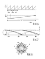
- the pattern of the pitch length L may be one in which, as shown in Fig. 9, the area of conductive substance (or magnetic substance) gradually increases and decreases.
- the pattern of the spiral strips with the short pitch is detected by a detection head which is adapted to form flux on a part of circumference of the rod section 3 and the pattern of the long pitch is detected by a detection head which is adapted to form flux on the entire circumference of the rod section 3.
- the pattern of the short pitch P is omitted in Fig. 9.
- the pattern of the long pitch L is not limited to one pitch only but may be provided over a longer range.
- the number of the detection heads and patterns corresponding thereto is not limited to two but the third, fourth etc. detection heads and patterns may be further provided. By this arrangement, the range within which detection of position can be made in an absolute value can be further expanded.
- the detection head 2 which forms the flux in the radial direction of the rod section 3 is not limited to the above described four-pole type or eight-pole type one but a detection head of other pole type such as a three-pole type, six-pole type or twelve-pole type may also be employed.
- a head 2 of a six-pole type is shown in Fig. 10.
- the primary coil exciting AC signals used for the phase system detection are not signals such as a sine signal and a cosine signal which are out of phase by 90 degrees but AC signals such as sin ⁇ t on one hand and sin ( ⁇ t - 60) or sin ( ⁇ t - 120) or sin ( ⁇ t - 240) on the other, which are out of phase by 60 degrees or its multiples or AC signals which are out of phase by a suitable phase angle.
- the pattern corresponding to this may consist of the single threaded screw type strip 3b as shown in Fig. 2 if there are no poles of the same phase in diametrically opposed positions and the pattern may consist also of the double threaded screw type strips 3b1 and 3b2 as shown in Fig. 7 if there are poles of the same phase in diametrically opposed positions.
- a pattern of double threaded screw type spiral strips 3b1 and 3b2 is provided.
- the head 1 which forms the flux in the axial direction of the rod section 3 is not limited to the four phase type as described above but may consist of two phases, three phases or other number of phases.
- the detection head which forms the flux in the radial direction of the rod section 3 is not limited to the one in which the respective poles are continuously formed with a common core material as shown in Figs. 4, 8 and 10 but may be one which consists of U-shaped cores 5, 6, 7 and 8 which are separated for the respective poles as shown in Fig. 11.
- Each of the cores 5 through 8 has two end portions and a flux coming out of one end portion and entering the other end portion passes in the radial direction on the surface of the rod section 3 (at least on the surface on which the pattern is disposed).
- the spiral pattern need not consist of a smooth spiral strip such as strips 3b, 3b1 and 3b2 but may consist of a stepwisely disposed pattern 3b' as shown in Fig. 12. In short, it will suffice if the pattern exhibits change which more or less resembles a spiral.
- the rod section 3 on which the patterns are provided is made of a circular rod but it may be made of a square rod or a rod of other configuration.
- Fig. 13 shows an example in which the rod section 3 is made of a square rod.
- Fig. 13(a) is a front view
- Fig 13(b) is a bottom view
- Fig. 13(c) is a cross sectional view.
- the first and second patterns may be provided.
- the first pattern consists of repeatedly provided square rings 3a and the second pattern consists of a single strip 3b obliquely (i.e., spirally) disposed around the square rod.
- Fig. 13 shows an example in which the rod section 3 is made of a square rod.
- Fig. 13(a) is a front view
- Fig 13(b) is a bottom view
- Fig. 13(c) is a cross sectional view.
- the first and second patterns may be provided.
- the first pattern consists of repeatedly provided square rings 3a
- FIG. 14 shows another example of the second pattern in a square rod section 3 of a square cross section in which Fig. 14(a) is a front view and Fig. 14(b) is a bottom view.
- the second pattern consists of rhombic portions 3b-D1, 3b-D2 Vietnamese disposed on respective four sides of the square rod section 3.
- the positions of the rhombic portions 3b-D1, 3b-D2 of adjacent sides are different by 1/4 of one pitch length L of the pattern.
- the shape of the second pattern in the square rod section 3 may also be a triangle 3b-T as shown in Fig. 15.
- the rhombic or triangle second pattern as shown in Fig. 14 or Fig. 15 may be used also for the ciurcular rod section 3.
- the same detection heads 1 and 2 as used in the example of Fig. 1 may be used for detecting the pattern (though their overall configuration may be square in conformity with the square cross section of the rod section 3).
- a material on which the patterns are porvided is not limited to a rod but it may be made of a flat bar or it may be a flat or curved plane portion of any member.
- Fig. 16 shows an example in which the patterns are disposed on an elongated flat bar member 31.
- Fig. 16(a) is a plan view of the flat member 31 and
- Fig. 16(b) is a side sectional view of the flat member 31 and a detection head provided adjacent to the flat member 31.
- the patterns provided on the flat member 31 are of shapes obtained by developing the first and second patterns of the rod section 3 shown in Fig. 2.
- the first pattern is formed by repeatedly providing materials 31a in the longitudinal direction with an interval P/2, which materials 31a extending laterally with a width of P/2.
- the second pattern consists of a single strip 31b which extends obliquely in the direction of displacement (i.e., longitudinal direction).
- a first detection head 1 which responds to the first pattern 31a consists of coils of four phases (each phase including primary and secondary coils), the coils of the phases A and C being wound about a magnetic substance core 32 of an E-shaped cross section and the coils of the phases B and D being wound about a magnetic substance core 33 of a likewise E-shaped cross section. Positional relation of the coils of the respective phases A through D is the same as in the example of Fig. 3.
- a second detection head 2 which responds to the second pattern 31b consists of four separated magnetic substance cores 34 through 37 corresponding to the four phases A through D and primary and secondary coils wound about the respective cores.
- the cores 34 through 37 of the respective phases are disposed with a predetermined interval (this interval corresponds to the interval of 90 degrees of the poles PA through PD in Fig. 4) in the lateral direction of the flat member 31.
- coils of the respective phases need not be disposed close to each other but they may be disposed in a spaced away relation.
- Fig. 17 shows an example of such spaced away arrangement.
- the component parts of the patterns of the rod section 3 and the detection heads are entirely the same as those in Fig. 3 but coils 1A l , 1A2, 1C l , 1C2 of the phases A and C and coils 1B l , 1B2, 1D1, 1D2 of the phases B and D which constitute the first detection head 1 are spaced from each other and a second detection head 2 is disposed therebetween.
- the first detection head 1 for detecting the first pattern consisting of the repeatedly arranged rings 3a as shown in Fig. 2 may be modified as shown in Figs. 18 and 19.
- a plurality of cores 29 producing flux in the radial direction of the rod section 3 are arranged side by side and close to each other in the circumferential direction to form a head 30A for one phase and these heads for a necessary number of phases, e.g., 30A through 30D, are provided with a predetermined interval therebetween in the axial direction as shown in Fig. 16.
- the cores 29 are U-shaped cores having two ends in the same manner as the cores 5 through 8 shown in Fig. 11 and primary and secondary coils are wound about these cores 29.
- the cores 29 of the same phase are excited by the same AC signal (e.g., the head 30A of the phase A is excited by a sine signal sin ⁇ t) and signal induced in the secondary coil is added and combined therewith.
- the direction of the flux produced by the respective cores 29 of the first head 1 shown in Figs. 18 and 19 is the radial direction of the rod section 3 as in the second head 2, this head 1 performs substantially the same operation as the first head 1 shown in Fig. 1 consisting of the coils which produce flux in the axial direction of the rod section 3.
- the head 1 which is constructed by arranging the cores 29 of the same phase side by side and close to each other in the circumferential direction performs the detection operation in a position in which it is disposed covering the entire range in the lateral direction of the rod section 3.
- the flux produced by the head extends over the entire circumference of the rod section 3 so that the head performs substantially the same operation as the first head 1 shown in Fig. 1.
- plural detection heads are provided in correspondence to the respective pattern.
- a common detection head may be provided for all of the patterns.
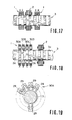
- Figs. 20 through 22 show an example of such common detection head.
- the patterns provided on the rod section 3 are the same as those shown in Fig. 2.
- the detection head functions as a single detection head by combination of heads 38 through 41 corresponding to the respective phases A through D disposed with an interval of P ( n ⁇ 1/4) in the longitudinal direction of the rod section 3. Sections in the radial direction of the heads 38 through 41 of the respective phases are shown in Figs. 21(a) through 21(d) as sectional views along lines A - A, B - B, C - C and D - D in Fig. 20.
- the heads 38 through 41 of the respective phases are of the same construction, each having a magnetic core with four poles (distinguished from one another by reference characters a, b, c and d) disposed with an interval of 90 degrees and one primary coil 1W and two secondary coils 2W1, 2W2 being wound about each of these poles.
- the respective poles a through d of head 38 of the phase A show reluctance change in the same phase with respect to the first pattern consisting of the repeatedly provided rings 3a
- the respective poles a through d of the head 39 of the phase B also show reluctance change in the same phase with respect to the first pattern and so do the head 40 of the phase C and the head 41 of the phase D.
- the phases of the reluctance change of the respective phases A through D shown with respect to the first pattern are different by one pitch length P, i.e., 90 degrees when one cycle is 360 degrees in the same manner as the previously described first detection head 1.
- the reluctance can be changed according to the displacement x with such function characteristics that the phase A shows cos ⁇ , the phase B sin ⁇ , the phase C - cos ⁇ and the phase D - sin ⁇ .
- the poles a show reluctance change of the same phase in all phases A through D
- the poles b also show reluctance change of the same phase in all phases A through D and so do the poles c and the poles d.
- the phases of the reluctance change of the respective poles a through d shown with respect to the second pattern are different by 90 degrees when one pitch length L, i.e., one cycle is 360 degrees in the same manner as the second head 2 shown in Fig. 4.
- the reluctance can be changed according to the displacement x with such function characteristics that the pole a is cos ⁇ , the pole b sin ⁇ , the pole c - cos ⁇ and the pole d - sin ⁇ .
- the primary coils 1W of the respective phases A through D and the respective poles a through d are excited by two reference signals sin ⁇ t and cos ⁇ t using the connection as shown in Fig. 22. That is, the poles a and c of the phases A and C are excited by sin ⁇ t and the poles b and d of the phases A and C are excited by - sin ⁇ t. The poles a and c of the phases B and D are excited by cos ⁇ t and the poles b and d of the phases B and D are excited by - cos ⁇ t.
- Aa sin ⁇ t cos ⁇ + sin ⁇ t cos ⁇ ⁇ ⁇ ⁇ ⁇ ... (3)
- the first term represents the induced voltage in response to the first pattern and the second term represents the induced voltage in response to the second pattern.
- Fig. 22 is a connection diagram in which one coil 2W l in the two secondary coils wound about each pole of each phase is connected in the manner of the above equation (4) to provide the output signal Y1 (for the vernier) responsive to the first pattern and the other secondary coil 2W2 is connected in the manner of the above equation (5) to provide the output signal Y2 (for the main scale) responsive to the second pattern.
- the secondary output voltages Aa through Dd of the respective poles of the respective phases as shown in the above equation (3) are separately derived from the secondary coil group 2W and these voltages are supllied to an operation circuit 42 in which the operation of the equation (4) is performed for providing the output signal Y1 responsive only to the first pattern while these voltages are supplied to an operation circuit 43 in which the operation of the equation (5) is performed for providing the output signal Y2 responsive only to the second pattern.
- the position detection data is obtained according to the phase system.
- position detection data having a voltage level corresponding to the position may be obtained in accordance with a voltage system as is well known by a conventional differential transformer. In that case, the provision of the phase difference in the AC signals for exciting the primary coils is unnecessary. Further, an arrangement may be made so that the position detection data Dx1 which requires a high degree of accuracy is obtained by the phase system and the other position detection data is obtained by the voltage system.
- a phase component and a voltage component may be separated from the output signal of the single detection head and the position detection data Dx1 of a high resolution used for the vernier may be obtained by the voltage system and the position detection data used for the main scale may be obtained by the voltage system.
- Material of a good conductor or magnetic substance for constituting the patterns 3a, 3b, 3b l and 3b2 may be deposited or formed on the rod section 3 by utilizing a suitable surface treatment technique (such as electroplating, flame spraying, baking, coating, solvent welding, vapor deposition, electroforming and photoetching).
- a suitable surface treatment technique such as electroplating, flame spraying, baking, coating, solvent welding, vapor deposition, electroforming and photoetching.
- Fig. 24 shows an example in which a base member 3d of the rod section 3 is formed thereabout with the patterns 3a and 3b made of a good conductor such as copper and is provided thereon with a surface coating 3e by means of, e.g., plating with chromium.
- the base member 3d is plated on its entire circumferential surface with copper and thereafter an unnecessary portion is removed by a removing technique such as etching to form the desired patterns 3a and 3b with the remaining plated portion.
- the surface coating 3e such as plating with chromium is applied for finishing the surface.
- Magnetic substance such as iron is a suitable material for the base member 3d because it facilitates passing of flux therethrough.
- Resins such as plastics and other materials may also be used as the base member 3d.
- the surface of the preformed plastic base member 3d may be plated with metal, e.g., copper, or a metal film such as a copper film may be preformed on a metal cavity by means of electroforming and thereafter plastic may be injection molded to be integrated with the metal film.
- the surface coating is made in such a manner that the recesses between the patterns 3a are filled with the surface coating 3e as shown in Fig. 24, the coating 3e tends to sink with resulting difficulty in obtaining a smooth surface finishing. Therefore, as shown in Fig. 25, the recesses between the patterns 3a are preferably filled with suitable pads 3f and the surface coating 3e is applied thereon.
- the pads 3f may be formed by, e.g., plating with nickel.
- the base member 3d is plated with a metal such as copper and thereafter etching is applied in a desired pattern, there is a likelihood that the surface of the base member 3d is corroded by the etching agent used. Particularly so if the base member 3d is made of a metal such as iron.
- a thin film of a predetemined material 3g e.g., resin
- plating with copper is applied thereon and thereafter etching is applied to form the patterns 3a.
- a composite pattern of the two patterns may be formed at once or, alternatively, one pattern may be formed first and the other pattern may be formed thereon in an overlapping fashion.
- the material constituting the patterns is not limited to a good conductor such as copper or aluminum or a mixture or a compound thereof which produces reluctance change by the eddy current loss but may be magnetic substance (e.g., iron or a compound or mixture thereof) which produces reluctance change due to the change in permeability.
- the patterns can be formed by selectively empolying the various surface treatment techniques described above.
- a desired pattern may be formed by constituting the base member 3d of the rod section 3 of magnetic substance such as iron, forming recesses corresponding to the desired pattern on the base member 3d by machining it and filling these recesses with a good conductor 3a.
- the projecting portions of the base member 3d consisting of magnetic substance enter the intervals between the patterns of the good conductors 3a and, in these portions, reluctance change which is small due to relatively small eddy current loss becomes further smaller due to projection of the magnetic substance whereby accuracy in response of the sensor output signal to the displacement of the rod section is improved in a synergistic manner.
- projecting portions 3a corresponding to a desired pattern may be formed by machining on the surface of the base member 3d consisting of magnetic substance of the rod section 3 and these projections 3a may be used as the patterns consisting of magnetic substance. In this case, reluctance change corresponding not to eddy current loss but to permeability change can be produced.
- the patterns disposed on a pattern provided member need not be visibly distinguishable but have only to be distinguished from the rest of portion in its magnetic characteristic.
- the base member 3d of the rod section 3 with stainless steel and heating this base member of stainless steel locally by suitable means such as laser beam in accordance with a desired pattern, the heated portion is converted to magnetic substance.
- the portion of the pattern can be made a magnetic substance portion while the rest of portion remains a non-magnetic substance portion notwithstanding that the pattern and the base member are both made of stainless steel.
- patterns of different forms are provided in a mixed state on a common region on the rod section, i.e., the pattern provided member.
- the invention is applicable not only to these but also to a case where two (or more) patterns of the same form are disposed along different channels on the pattern provided member or to a case where different patterns are disposed along different channels on the pattern provided member.
- the term "channel” herein means a region provided with a pattern extending in the longitudinal direction of the pattern provided member, i.e., the rod section.
- Figs. 29 and 30 show an example of such embodiment.
- the cylindrical side surface of a rod section 44 is divided into four channels in which two opposed channels CH1 and CH3 are provided with the first pattern of the same form and other opposed two channels CH2 and CH4 are provided with the second pattern of the same form.
- the first pattern is formed by repeatedly disposing rectangular patterns 44a at equal interval with one pitch length P1.
- the second pattern is formed by repeatedly disposing rectangular patterns 44b at equal interval with one pitch length P2.
- An absolute position can be detected within the range of P1 ⁇ n.
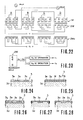
- FIG. 31 An example of the detection head used for this rod section 44 is shown in Fig. 31.
- a first detection head 45 corresponding to the first pattern 44a and a second detection head 46 corresponding to the second pattern 44b both consist of primary and secondary coils of four phases A through D with the rod section 44 being inserted through a space defined in the coils.
- the coil length of the first head 45 for one phase is P1/2 and the coil length of the second head 46 for one phase is P2/2.
- Positional relation between the coils of the phases A through D is the same as the one shown in Fig. 1.
- a masking 47 is provided inside the coil in a position corresponding to the second pattern 44b. This head 45 responds only to the first pattern 44a and does not respond to the second pattern 44b.
- a masking 48 is provided inside the coil in a position corresponding to the first pattern 44a. This head 46 responds only to the second pattern 44b and does not respond to the first pattern 44a.
- the maskings 47 and 48 consist of material which acts on the flux in a similar manner to the material constituting the patterns 44a and 44b.
- the maskings 47 and 48 are preferably made of the same material as the patterns 44a and 44b but need not be the entirely same material.
- the maskings 47 and 48 function to prevent the detection heads 45 and 46 from reacting to the periodical change of the patterns 44b and 44a in the masked portions and thereby substantially prevents induction of voltage in response to the change in the patterns.
- FIG. 32 Another example of detection heads applicable to the rod section 44 is shown in Fig. 32.
- a pole consisting of a U-shaped magnetic substance core and primary and secondary coils wound about it is provided for the respective phases A through D so that flux will be formed in the radial direction of the rod section 44.
- the first detection head 45 is provided in correspondence to the arrangement of the first pattern 44a and the second detection head 46 to the second pattern 44b.
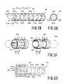
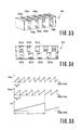
- FIG. 29 The arrangement of the pattern as shown in Fig. 29 can of course be carried out in a square rod 49 as in Fig. 33.
- Reference character 49a represents the pattern of the pitch P1 and reference character 49b represents the pattern of the pitch P2.
- patterns 50a and 50b of different pitches as shown in Fig. 34 may be disposed along different channels.
- the detection heads 45 and 46 the same ones shown in Fig. 32 may be used.
- patterns of the same form and different repeating pitches are disposed along separate channels.
- patterns of different forms as shown in Figs. 1 through 20 may of course be disposed in separate channels as in Figs. 29, 33 and 34.
- the absolute position data Dx within an expanded range can be obtained.
- the present position is determined by the absolute value which is of a high accuracy and besides the range within which detection can be made in the absolute value is a range P1 ⁇ n or P2 ⁇ (n - 1) which is greatly expanded from one pitch length P1 or P2.
- the primary coils and secondary coils for the respective phases in the detection heads need not be separate coils but may be common ones as those described in Japanese Preliminary Utility Model Publication No. 2621/1983 or No. 39507/1983.
- the rod section on which the patterns are disposed and other members may be a part of a machine or equipment which is the object of detection. If, for example, the present invention is applied to a device for detecting a position of a piston rod for a hydraulic cylinder, the pitston rod is utilized as the pattern provided member of the present invention.
- a guide bar for guiding a displacing member in a machine may be utilized as the pattern provided member of the present invention and a detection head which is interlocked with the displacing member may be displaced along the guide bar (i.e., the pattern provided member).
- two or more types of patterns are provided on a rod or other pattern provided member and a position detection signal corresponding to a positional relation of a detection head with respect to the pattern provided member is obtained for each of these patterns.
Landscapes
- Engineering & Computer Science (AREA)
- Physics & Mathematics (AREA)
- Fluid Mechanics (AREA)
- Mechanical Engineering (AREA)
- General Engineering & Computer Science (AREA)
- Theoretical Computer Science (AREA)
- Transmission And Conversion Of Sensor Element Output (AREA)
- Measurement Of Length, Angles, Or The Like Using Electric Or Magnetic Means (AREA)
Applications Claiming Priority (2)
| Application Number | Priority Date | Filing Date | Title |
|---|---|---|---|
| JP175145/85 | 1985-08-09 | ||
| JP60175145A JP2554465B2 (ja) | 1985-08-09 | 1985-08-09 | アブソリユ−ト位置検出装置 |
Publications (3)
| Publication Number | Publication Date |
|---|---|
| EP0212406A2 true EP0212406A2 (de) | 1987-03-04 |
| EP0212406A3 EP0212406A3 (en) | 1989-04-19 |
| EP0212406B1 EP0212406B1 (de) | 1991-10-16 |
Family
ID=15991067
Family Applications (1)
| Application Number | Title | Priority Date | Filing Date |
|---|---|---|---|
| EP86110717A Expired - Lifetime EP0212406B1 (de) | 1985-08-09 | 1986-08-02 | Gerät zur absoluten Linearlageerkennung |
Country Status (4)
| Country | Link |
|---|---|
| US (2) | US4879555A (de) |
| EP (1) | EP0212406B1 (de) |
| JP (1) | JP2554465B2 (de) |
| DE (1) | DE3681997D1 (de) |
Cited By (10)
| Publication number | Priority date | Publication date | Assignee | Title |
|---|---|---|---|---|
| DE3900866A1 (de) * | 1989-01-13 | 1990-07-19 | Heimeier Gmbh Metall Theodor | Anordnung zur steuerung eines heiz- oder kuehlmediums |
| WO2004099724A3 (en) * | 2003-05-06 | 2005-02-24 | Stanford Res Inst Int | Hydraulic cylinder with piston and a magnetic layer on the piston rod for piston position determination |
| US7259553B2 (en) | 2005-04-13 | 2007-08-21 | Sri International | System and method of magnetically sensing position of a moving component |
| FR2958393A1 (fr) * | 2010-04-01 | 2011-10-07 | Peugeot Citroen Automobiles Sa | Dispositif de mesure et demarreur comprenant un tel dispositif |
| WO2011135063A3 (de) * | 2010-04-30 | 2012-03-01 | Continental Automotive Gmbh | Magnetisches längenmesssystem, längenmessverfahren sowie herstellungsverfahren eines magnetischen längenmesssystems |
| US8970208B2 (en) | 2010-02-11 | 2015-03-03 | Sri International | Displacement measurement system and method using magnetic encodings |
| FR3031588A1 (fr) * | 2015-01-13 | 2016-07-15 | Dymeo | Capteurs inductifs de deplacement |
| US10480580B2 (en) | 2015-01-13 | 2019-11-19 | Hutchinson | Bearing comprising an angular movement sensor |
| US10564007B2 (en) | 2015-01-13 | 2020-02-18 | Hutchinson | Inductive movement sensors |
| US10564008B2 (en) | 2015-01-13 | 2020-02-18 | Hutchinson | Inductive displacement sensors |
Families Citing this family (45)
| Publication number | Priority date | Publication date | Assignee | Title |
|---|---|---|---|---|
| JPH0264407A (ja) * | 1988-08-31 | 1990-03-05 | Fanuc Ltd | 磁気式絶対位置エンコーダ |
| EP0388584B1 (de) * | 1989-01-17 | 1993-10-27 | Gec Alsthom Sa | Vorrichtung zur Ermittlung der Lage einer mit einem elektrisch diskontinuierlich leitenden Band umgebenen rotierenden Stahlwelle sowie Verfahren zur Herstellung des Bandes |
| US5457368A (en) * | 1993-03-09 | 1995-10-10 | University Of Utah Research Foundation | Mechanical/electrical displacement transducer |
| US5461311A (en) * | 1992-12-24 | 1995-10-24 | Kayaba Kogyo Kabushiki Kaisha | Rod axial position detector including plural scales wherein nonmagnetized portions have differing spacing and differing depths and means for calculating the absolute position are provided |
| US5497083A (en) * | 1992-12-24 | 1996-03-05 | Kayaba Kogyo Kabushiki Kaisha | Rod axial position detector including a first scale having equidistant magnetic parts and a second scale having unequally distant parts and differing field strengths |
| US5691646A (en) * | 1994-12-07 | 1997-11-25 | Mitutoya Corporation | Capacitance-type displacement measuring device with electrodes having spiral patterns |
| EP0743508A2 (de) * | 1995-05-16 | 1996-11-20 | Mitutoyo Corporation | Positionssensor unter Anwendung des Strominduktionsprinzips |
| US5748111A (en) * | 1996-03-29 | 1998-05-05 | Caterpillar Inc. | Apparatus for monitoring the speed and axial position of a rotating member |
| JP2960013B2 (ja) * | 1996-07-29 | 1999-10-06 | 慧 清野 | 移動物体の検出用目盛及びこれを用いた移動物体の検出装置 |
| US5936400A (en) * | 1996-12-23 | 1999-08-10 | Federal Products Co. | Magnetoresistive displacement sensor and variable resistor using a moving domain wall |
| US5886519A (en) * | 1997-01-29 | 1999-03-23 | Mitutoyo Corporation | Multi-scale induced current absolute position transducer |
| JPH11160009A (ja) * | 1997-10-31 | 1999-06-18 | Samsung Heavy Ind Co Ltd | ストロークセンシングシリンダの絶対位置検出方法 |
| US6147342A (en) * | 1998-06-02 | 2000-11-14 | Caterpillar Inc. | Encoding system for determining the position of a cylinder rod along a path of movement |
| US6327791B1 (en) | 1999-06-09 | 2001-12-11 | The Government Of The United States As Represented By The Secretary Of Commerce | Chain code position detector |
| CA2332712C (en) * | 2001-01-29 | 2006-07-11 | Vtech Communications, Ltd. | Two-axis cursor control apparatus |
| JP2002243402A (ja) * | 2001-02-22 | 2002-08-28 | Juki Corp | 直動軸の位置検出構造及び電子部品搭載用ヘッド |
| JP4088073B2 (ja) * | 2002-01-11 | 2008-05-21 | 株式会社ミツトヨ | 絶対位置測定装置 |
| US8882657B2 (en) | 2003-03-07 | 2014-11-11 | Intuitive Surgical Operations, Inc. | Instrument having radio frequency identification systems and methods for use |
| US20040176683A1 (en) * | 2003-03-07 | 2004-09-09 | Katherine Whitin | Method and apparatus for tracking insertion depth |
| JP4247822B2 (ja) * | 2003-04-22 | 2009-04-02 | 株式会社アミテック | シリンダ位置検出装置 |
| US7141988B2 (en) * | 2003-07-01 | 2006-11-28 | Tiax Llc | Capacitive position sensor and sensing methodology |
| US7243557B2 (en) * | 2003-12-30 | 2007-07-17 | Nctengineering Gmbh | Torque sensor |
| JP4419692B2 (ja) * | 2004-06-07 | 2010-02-24 | 株式会社ジェイテクト | 角度検出装置 |
| JP4713584B2 (ja) * | 2004-07-14 | 2011-06-29 | テネコ オートモティブ オペレーティング カンパニー インコーポレイテッド | 一体化された変位センサをもつショックアブソーバ |
| US7191943B2 (en) * | 2004-07-28 | 2007-03-20 | Caterpillar Inc | Robust barcode and reader for rod position determination |
| US7530948B2 (en) * | 2005-02-28 | 2009-05-12 | University Of Washington | Tethered capsule endoscope for Barrett's Esophagus screening |
| GB0513000D0 (en) * | 2005-06-24 | 2005-08-03 | Rolls Royce Plc | A method and probe for determining displacement |
| JP4950713B2 (ja) * | 2007-03-20 | 2012-06-13 | オークマ株式会社 | アブソリュートエンコーダ |
| US20090102467A1 (en) * | 2007-10-22 | 2009-04-23 | Johnson Controls Inc. | Method and apparatus for sensing shaft rotation |
| WO2009053812A2 (en) * | 2007-10-22 | 2009-04-30 | A.M.A. S.P.A. | System for determining the position of a piston along its path of travel for a fluid-dynamic actuator |
| GB0903961D0 (en) * | 2009-01-27 | 2009-04-22 | Renishaw Plc | Magnetic encoder scale |
| JP5421646B2 (ja) * | 2009-04-23 | 2014-02-19 | カヤバ工業株式会社 | シリンダのストロークセンサ |
| US9222804B2 (en) * | 2011-09-02 | 2015-12-29 | Persimmon Technologies Corporation | System and method for position sensing |
| GB201311856D0 (en) * | 2013-07-02 | 2013-08-14 | Gill Res And Dev Ltd | A position indicator device |
| JP6365824B2 (ja) * | 2014-05-27 | 2018-08-01 | 村田機械株式会社 | 磁気式変位センサ及び変位の検出方法 |
| US9267819B2 (en) | 2014-06-12 | 2016-02-23 | Mitutoyo Corporation | Absolute position encoder scale having plates alternating with varying recesses |
| US20160054149A1 (en) * | 2014-08-20 | 2016-02-25 | Zedi Canada Inc. | System and method for tracking linear position and rotation of a piston |
| US9435663B2 (en) | 2014-08-22 | 2016-09-06 | Mitutoyo Corporation | Absolute position encoder scale having layers in a stacked configuration |
| BR112017012991B1 (pt) * | 2014-12-19 | 2021-07-13 | Weber-Hydraulik Gmbh | Método para a aplicação de uma inscrição e/ou de uma marcação, e cilindro para fluido |
| EP3271732A1 (de) * | 2015-03-18 | 2018-01-24 | Exxonmobil Upstream Research Company | Einzelsensorsysteme und verfahren zur gegenlauferkennung |
| US9683869B1 (en) * | 2015-12-11 | 2017-06-20 | Mitutoyo Corporation | Electronic absolute position encoder |
| US10344573B2 (en) * | 2016-03-08 | 2019-07-09 | Weatherford Technology Holdings, Llc | Position sensing for wellsite pumping unit |
| US10577078B2 (en) * | 2017-04-24 | 2020-03-03 | General Electric Company | Systems and methods for electronic measurement of propeller blade angle |
| EP3410075B1 (de) * | 2017-05-30 | 2020-10-07 | MEAS France | Temperaturkompensation für magnetfeldmessvorrichtungen und magnetfeldmessvorrichtung damit |
| DE102021127161A1 (de) | 2021-10-20 | 2022-12-15 | Schaeffler Technologies AG & Co. KG | Scheibenläufermotor und Verfahren zur Montage eines Scheibenläufermotors |
Citations (5)
| Publication number | Priority date | Publication date | Assignee | Title |
|---|---|---|---|---|
| GB1139691A (en) * | 1965-01-14 | 1969-01-08 | Zeiss Stiftung | A device for the absolute digital presentation of measuring values |
| US3641467A (en) * | 1969-05-13 | 1972-02-08 | Allis Chalmers Mfg Co | Rotary inductor |
| GB2096421A (en) * | 1981-04-07 | 1982-10-13 | Secretary Industry Brit | Position transducer for fluid actuated ram |
| GB2098332A (en) * | 1979-11-14 | 1982-11-17 | Festo Maschf Stoll G | Position sensor |
| JPS59226822A (ja) * | 1983-06-07 | 1984-12-20 | Matsushita Electric Works Ltd | ロ−タリエンコ−ダ |
Family Cites Families (13)
| Publication number | Priority date | Publication date | Assignee | Title |
|---|---|---|---|---|
| US3041598A (en) * | 1958-06-30 | 1962-06-26 | Ibm | Electronic translating means |
| US2905874A (en) * | 1958-10-30 | 1959-09-22 | Gen Electric | Position control system and device |
| US3171104A (en) * | 1959-10-13 | 1965-02-23 | Sperry Rand Corp | Variable reluctance binary data transducer |
| US3286252A (en) * | 1963-11-15 | 1966-11-15 | Gen Precision Inc | Capacity encoder |
| US3505576A (en) * | 1966-07-12 | 1970-04-07 | Litton Business Systems Inc | Digital servomechanism including an inductive position encoder |
| US3534361A (en) * | 1967-01-11 | 1970-10-13 | Itek Corp | Photo-optical analog to digital converter |
| JPS57135917U (de) * | 1981-02-20 | 1982-08-25 | ||
| JPS58106691A (ja) * | 1981-12-21 | 1983-06-25 | 株式会社エスジ− | アブソリュート位置検出装置 |
| JPS5923609U (ja) * | 1982-08-04 | 1984-02-14 | 株式会社エスジ− | シリンダ位置検出装置 |
| JPS5923610U (ja) * | 1982-08-06 | 1984-02-14 | 株式会社エスジ− | シリンダ位置検出装置 |
| JPS59164406A (ja) * | 1983-03-03 | 1984-09-17 | Taiyo Tekko Kk | ストローク位置検出用ピストンロッドの製造方法 |
| US4717874A (en) * | 1984-02-10 | 1988-01-05 | Kabushiki Kaisha Sg | Reluctance type linear position detection device |
| JPS61281902A (ja) * | 1985-06-07 | 1986-12-12 | Toshiba Mach Co Ltd | 絶対位置検出装置 |
-
1985
- 1985-08-09 JP JP60175145A patent/JP2554465B2/ja not_active Expired - Fee Related
-
1986
- 1986-08-02 EP EP86110717A patent/EP0212406B1/de not_active Expired - Lifetime
- 1986-08-02 DE DE8686110717T patent/DE3681997D1/de not_active Expired - Fee Related
- 1986-08-04 US US06/893,254 patent/US4879555A/en not_active Expired - Lifetime
-
1989
- 1989-08-15 US US07/394,205 patent/US4951048A/en not_active Expired - Lifetime
Patent Citations (5)
| Publication number | Priority date | Publication date | Assignee | Title |
|---|---|---|---|---|
| GB1139691A (en) * | 1965-01-14 | 1969-01-08 | Zeiss Stiftung | A device for the absolute digital presentation of measuring values |
| US3641467A (en) * | 1969-05-13 | 1972-02-08 | Allis Chalmers Mfg Co | Rotary inductor |
| GB2098332A (en) * | 1979-11-14 | 1982-11-17 | Festo Maschf Stoll G | Position sensor |
| GB2096421A (en) * | 1981-04-07 | 1982-10-13 | Secretary Industry Brit | Position transducer for fluid actuated ram |
| JPS59226822A (ja) * | 1983-06-07 | 1984-12-20 | Matsushita Electric Works Ltd | ロ−タリエンコ−ダ |
Non-Patent Citations (2)
| Title |
|---|
| PATENT ABSTRACTS OF JAPAN, vol. 9, no. 101 (P-353)[1824], 2nd May 1985; & JP-A-59 226 822 (MATSUSHITA DENKO K.K.) 20-12-1984 * |
| PROCEEDINGS OF IRE, vol. 43, no. 8, August 1955, pages 960-966, US; R.P. STONE et al.: "A time-sampling and amplitude-quantizing tube" * |
Cited By (17)
| Publication number | Priority date | Publication date | Assignee | Title |
|---|---|---|---|---|
| DE3900866C2 (de) * | 1989-01-13 | 2001-11-22 | Heimeier Gmbh Metall Theodor | Anordnung zur Steuerung eines Heiz- oder Kühlmediums |
| DE3900866A1 (de) * | 1989-01-13 | 1990-07-19 | Heimeier Gmbh Metall Theodor | Anordnung zur steuerung eines heiz- oder kuehlmediums |
| WO2004099724A3 (en) * | 2003-05-06 | 2005-02-24 | Stanford Res Inst Int | Hydraulic cylinder with piston and a magnetic layer on the piston rod for piston position determination |
| US6989669B2 (en) | 2003-05-06 | 2006-01-24 | Sri International | Systems and methods of recording piston rod position information in a magnetic layer on a piston rod |
| US7034527B2 (en) | 2003-05-06 | 2006-04-25 | Sri International | Systems of recording piston rod position information in a magnetic layer on a piston rod |
| US7259553B2 (en) | 2005-04-13 | 2007-08-21 | Sri International | System and method of magnetically sensing position of a moving component |
| US7439733B2 (en) | 2005-04-13 | 2008-10-21 | Sri International | System and method of magnetically sensing position of a moving component |
| US8970208B2 (en) | 2010-02-11 | 2015-03-03 | Sri International | Displacement measurement system and method using magnetic encodings |
| FR2958393A1 (fr) * | 2010-04-01 | 2011-10-07 | Peugeot Citroen Automobiles Sa | Dispositif de mesure et demarreur comprenant un tel dispositif |
| WO2011135063A3 (de) * | 2010-04-30 | 2012-03-01 | Continental Automotive Gmbh | Magnetisches längenmesssystem, längenmessverfahren sowie herstellungsverfahren eines magnetischen längenmesssystems |
| US9410788B2 (en) | 2010-04-30 | 2016-08-09 | Continental Automotive Gmbh | Magnetic length measuring system, length measuring method and method for producing a magnetic length measuring system |
| FR3031588A1 (fr) * | 2015-01-13 | 2016-07-15 | Dymeo | Capteurs inductifs de deplacement |
| WO2016113500A1 (fr) * | 2015-01-13 | 2016-07-21 | Hutchinson | Capteurs inductifs de deplacement |
| US10480580B2 (en) | 2015-01-13 | 2019-11-19 | Hutchinson | Bearing comprising an angular movement sensor |
| US10557727B2 (en) | 2015-01-13 | 2020-02-11 | Hutchinson | Inductive displacement sensors |
| US10564007B2 (en) | 2015-01-13 | 2020-02-18 | Hutchinson | Inductive movement sensors |
| US10564008B2 (en) | 2015-01-13 | 2020-02-18 | Hutchinson | Inductive displacement sensors |
Also Published As
| Publication number | Publication date |
|---|---|
| EP0212406A3 (en) | 1989-04-19 |
| DE3681997D1 (de) | 1991-11-21 |
| JP2554465B2 (ja) | 1996-11-13 |
| EP0212406B1 (de) | 1991-10-16 |
| US4951048A (en) | 1990-08-21 |
| US4879555A (en) | 1989-11-07 |
| JPS6235202A (ja) | 1987-02-16 |
Similar Documents
| Publication | Publication Date | Title |
|---|---|---|
| US4951048A (en) | Absolute linear position detection device | |
| US4764767A (en) | Absolute rotational position detection device | |
| EP0182322A1 (de) | Einrichtung zum Erfassen der Drehlage | |
| US6005387A (en) | Reduced offset high accuracy induced current position transducer | |
| US4697144A (en) | Position sensing apparatus | |
| US20030160608A1 (en) | Induced current position transducers using tape scales with apertures | |
| US4554409A (en) | Method of electromagnetically reading coordinate data | |
| CN110375775B (zh) | 电磁感应式编码器 | |
| JPS6244603A (ja) | アブソリユ−ト直線位置検出装置 | |
| US20030196496A1 (en) | Relative-rotational-position detection apparatus | |
| JPH0665961B2 (ja) | 流体圧シリンダのピストンロッド位置検出装置 | |
| JPS60170702A (ja) | 直線位置検出装置及び該装置におけるロツド部の製造方法 | |
| JP2554479B2 (ja) | アブソリユ−ト位置検出装置 | |
| JPH0580603B2 (de) | ||
| US5453685A (en) | Inductive position sensing device and apparatus with selectable winding configuration | |
| JPH057522Y2 (de) | ||
| JPH0786422B2 (ja) | 直線位置検出装置におけるロッド部の製造方法 | |
| JP3592835B2 (ja) | 直線位置検出装置 | |
| JPH0618209A (ja) | 流体圧シリンダのピストンロッド位置検出装置 | |
| CN113614492B (zh) | 磁式线性传感器 | |
| JPH0478720B2 (de) | ||
| JP3030651B2 (ja) | 直線位置検出装置 | |
| KR20240042514A (ko) | 유도 인코더 시스템을 위한 이차 코일 어셈블리 및 유도 인코더 시스템 | |
| JPS6246202A (ja) | 回転位置検出装置 | |
| RU2075039C1 (ru) | Преобразователь линейных перемещений |
Legal Events
| Date | Code | Title | Description |
|---|---|---|---|
| PUAI | Public reference made under article 153(3) epc to a published international application that has entered the european phase |
Free format text: ORIGINAL CODE: 0009012 |
|
| AK | Designated contracting states |
Kind code of ref document: A2 Designated state(s): DE FR GB IT SE |
|
| PUAL | Search report despatched |
Free format text: ORIGINAL CODE: 0009013 |
|
| AK | Designated contracting states |
Kind code of ref document: A3 Designated state(s): DE FR GB IT SE |
|
| 17P | Request for examination filed |
Effective date: 19890622 |
|
| 17Q | First examination report despatched |
Effective date: 19900417 |
|
| GRAA | (expected) grant |
Free format text: ORIGINAL CODE: 0009210 |
|
| AK | Designated contracting states |
Kind code of ref document: B1 Designated state(s): DE FR GB IT SE |
|
| PG25 | Lapsed in a contracting state [announced via postgrant information from national office to epo] |
Ref country code: IT Free format text: LAPSE BECAUSE OF FAILURE TO SUBMIT A TRANSLATION OF THE DESCRIPTION OR TO PAY THE FEE WITHIN THE PRE;WARNING: LAPSES OF ITALIAN PATENTS WITH EFFECTIVE DATE BEFORE 2007 MAY HAVE OCCURRED AT ANY TIME BEFORE 2007. THE CORRECT EFFECTIVE DATE MAY BE DIFFERENT FROM THE ONE RECORDED.SCRIBED TIME-LIMIT Effective date: 19911016 Ref country code: SE Effective date: 19911016 |
|
| REF | Corresponds to: |
Ref document number: 3681997 Country of ref document: DE Date of ref document: 19911121 |
|
| ET | Fr: translation filed | ||
| PGFP | Annual fee paid to national office [announced via postgrant information from national office to epo] |
Ref country code: GB Payment date: 19920728 Year of fee payment: 7 |
|
| PLBE | No opposition filed within time limit |
Free format text: ORIGINAL CODE: 0009261 |
|
| STAA | Information on the status of an ep patent application or granted ep patent |
Free format text: STATUS: NO OPPOSITION FILED WITHIN TIME LIMIT |
|
| PGFP | Annual fee paid to national office [announced via postgrant information from national office to epo] |
Ref country code: FR Payment date: 19920831 Year of fee payment: 7 |
|
| 26N | No opposition filed | ||
| PG25 | Lapsed in a contracting state [announced via postgrant information from national office to epo] |
Ref country code: GB Effective date: 19930802 |
|
| GBPC | Gb: european patent ceased through non-payment of renewal fee |
Effective date: 19930802 |
|
| PG25 | Lapsed in a contracting state [announced via postgrant information from national office to epo] |
Ref country code: FR Effective date: 19940429 |
|
| REG | Reference to a national code |
Ref country code: FR Ref legal event code: ST |
|
| PGFP | Annual fee paid to national office [announced via postgrant information from national office to epo] |
Ref country code: DE Payment date: 20010730 Year of fee payment: 16 |
|
| PG25 | Lapsed in a contracting state [announced via postgrant information from national office to epo] |
Ref country code: DE Free format text: LAPSE BECAUSE OF NON-PAYMENT OF DUE FEES Effective date: 20030301 |