EP0211911B1 - Verfahren und vorrichtung zur vogelvergrämung - Google Patents
Verfahren und vorrichtung zur vogelvergrämung Download PDFInfo
- Publication number
- EP0211911B1 EP0211911B1 EP86901365A EP86901365A EP0211911B1 EP 0211911 B1 EP0211911 B1 EP 0211911B1 EP 86901365 A EP86901365 A EP 86901365A EP 86901365 A EP86901365 A EP 86901365A EP 0211911 B1 EP0211911 B1 EP 0211911B1
- Authority
- EP
- European Patent Office
- Prior art keywords
- fact
- frequency
- distinguished
- signals
- accordance
- Prior art date
- Legal status (The legal status is an assumption and is not a legal conclusion. Google has not performed a legal analysis and makes no representation as to the accuracy of the status listed.)
- Expired
Links
- 238000000034 method Methods 0.000 title claims description 17
- 230000007274 generation of a signal involved in cell-cell signaling Effects 0.000 claims description 7
- 230000000630 rising effect Effects 0.000 claims 1
- 241000271566 Aves Species 0.000 description 8
- 241001465754 Metazoa Species 0.000 description 5
- 230000005540 biological transmission Effects 0.000 description 3
- 238000002604 ultrasonography Methods 0.000 description 3
- 230000000694 effects Effects 0.000 description 2
- 241000894007 species Species 0.000 description 2
- 206010063659 Aversion Diseases 0.000 description 1
- 241000272161 Charadriiformes Species 0.000 description 1
- 241000272194 Ciconiiformes Species 0.000 description 1
- 241000699670 Mus sp. Species 0.000 description 1
- 108010076504 Protein Sorting Signals Proteins 0.000 description 1
- 241000700159 Rattus Species 0.000 description 1
- 206010039740 Screaming Diseases 0.000 description 1
- 241000287182 Sturnidae Species 0.000 description 1
- 241000607479 Yersinia pestis Species 0.000 description 1
- 238000010276 construction Methods 0.000 description 1
- 239000002420 orchard Substances 0.000 description 1
- 238000009372 pisciculture Methods 0.000 description 1
- 230000005855 radiation Effects 0.000 description 1
- 238000004088 simulation Methods 0.000 description 1
- 238000001228 spectrum Methods 0.000 description 1
- 230000001960 triggered effect Effects 0.000 description 1
Images

Classifications
-
- A—HUMAN NECESSITIES
- A01—AGRICULTURE; FORESTRY; ANIMAL HUSBANDRY; HUNTING; TRAPPING; FISHING
- A01M—CATCHING, TRAPPING OR SCARING OF ANIMALS; APPARATUS FOR THE DESTRUCTION OF NOXIOUS ANIMALS OR NOXIOUS PLANTS
- A01M29/00—Scaring or repelling devices, e.g. bird-scaring apparatus
- A01M29/16—Scaring or repelling devices, e.g. bird-scaring apparatus using sound waves
-
- G—PHYSICS
- G10—MUSICAL INSTRUMENTS; ACOUSTICS
- G10K—SOUND-PRODUCING DEVICES; METHODS OR DEVICES FOR PROTECTING AGAINST, OR FOR DAMPING, NOISE OR OTHER ACOUSTIC WAVES IN GENERAL; ACOUSTICS NOT OTHERWISE PROVIDED FOR
- G10K15/00—Acoustics not otherwise provided for
- G10K15/02—Synthesis of acoustic waves
Definitions
- the invention relates to a method and a device for scaring birds by discontinuous transmission of acoustic, frequency-modulated signals of limited duration.
- DE patent specification 1 260 855 an electronic device for simulating animal screaming, warning or call calls is known.
- the animal sounds are obtained synthetically from the frequency spectrum of pulse-controlled tone generators. The frequency in the repetition of these animal sounds is controlled by pulses from clocks.
- the electronic design of the device enables different animal sounds. be programmed so that the animals do not get used to the same sound.
- DE-OS 2 022 056 describes a method for chasing away rats and mice. For this purpose, the location where the pests are located is sonicated with ultrasound of a certain level, which is periodically frequency-modulated within a predetermined ultrasound frequency range.
- a method and a device for bird scare by discontinuous transmission of acoustic, frequency-modulated signals is known (GB-A 1 228 405).
- the transmitted signal has a carrier frequency between 500 and 5000 Hz.
- This signal is then amplitude-modulated in a frequency range between 50 and 300 Hz.
- This type of modulation has the disadvantage that there is only an unsatisfactory simulation of species-specific signals and is therefore frightening birds not suitable. This object is achieved by the features listed in the characterizing part of claim 1.
- the present invention is therefore based on the object of developing a method with which effective bird scaring is possible over an indefinitely long time.
- the bird scaring device to be implemented should be network-independent, have lower power consumption and have a simple and inexpensive construction.
- the device should be adaptable to different types of birds.
- the bird scaring device according to the invention has a sequence control with which the duration and / or the sequence of signals to be emitted can be defined and which controls a signal generation unit with frequency modulation device. It is only through frequency modulation of the frequency-modulated signal that suitable species-specific signals are obtained for bird aversion.
- the following subclaims describe preferred embodiments of the device according to the invention.
- frequency-modulated audible acoustic signals are not suitable for deterring birds, even if they are emitted as a sequence of differently modulated signals.
- the birds get used to these sounds or their transmission sequence after a relatively short time, so that a scaring effect can no longer be achieved.
- signals are generated which are modulated within a certain frequency range and have a certain modulation period. It turns out that, with a fixed or arbitrary radiation sequence of such signals, surprisingly no acclimatization occurs. It is essential that more than two, e.g. 16 to 32 signals are generated which differ in three of their parameters, namely in the frequency modulation range, in the modulation period and / or in the time duration.
- the time period between two successive signals can be varied as desired.
- the pause between the individual signals can be 20 seconds to 1 hour, preferably 1 to 30 minutes, in particular 5 to 20 minutes.
- Each signal should preferably be frequency modulated between 100 and 7000 Hz, in particular between 150 and 5000 Hz.
- the modulation period is between about 0.01 to 5 seconds, preferably 0.02 to 2 seconds, in particular 0.05 to 1 second.
- Special results are achieved if the range within which the frequency modulation takes place comprises at least 2000 Hz.
- the lower limit for the frequency modulation range should preferably be between 1000 and 100 Hz, in particular between 500 and 100 Hz.
- the duration of each individual signal is 1 to 30 seconds, preferably 10 to 15 seconds. With the measures according to the invention, a sound pressure level of about 60 dB at the point of action is sufficient. This also enables a permanent operation of the device according to the invention without there being any noise pollution for the residents.
- the inventive design of the device for carrying out such a method fulfills the requirements due to the special type of use. It is network-independent and has low power consumption. It can be triggered automatically and manually, has a simple circuit and is inexpensive to implement.
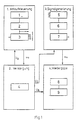
- Fig. 1 the overall concept of the device according to the invention is shown, which essentially consists of four units; Sequence control, signal generation, power supply and playback unit.
- the sequence control can consist of the trigger 1, the timer 2 and the counter 3. But it can also be done by a microprocessor.
- This control unit is connected to the supply unit with an accumulator 4.
- the signal generation essentially consists of the analog switch 5, the modulation generator 6 and the main generator 7. The reproduction is ensured by a power amplifier 8 and a loudspeaker 9.
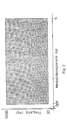
- the emitted signal is modulated within a certain frequency range and with a certain period, as shown in FIG. 2.
- the modulated frequency range used to deter birds is between 30 and 9000 Hz with a modulation period of e.g. 0.01 to 5 seconds.
- the signal can lie anywhere within this range, provided that the conditions mentioned are fulfilled.
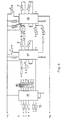
- the sequence control according to the invention essentially consists of an automatic trigger and / or a manual trigger.
- the trigger 10 in multivibrator circuit generates e.g. a trigger signal every 10 minutes.
- This trigger signal starts a monostable multivibrator 12.
- the falling edge of the pulse generated by the monostable multivibrator 12 switches the counter 13 one bit further and at the same time triggers another monostable multivibrator 14.
- This switches the supply voltage for signal generation and playback for a certain, variable period of time via a relay, not shown here, e.g. Be 10 seconds.
- this process is repeated every 10 minutes if the manual trigger 11 is not actuated in between.
- the counter 13 is implemented for 8 signals, each of which can be generated by advancing by 1 bit.
- the corresponding frequency-determined resistor 16 on the modulation generator 17 is designed via an 8-channel analog switch 15 shown in FIG. 4, with which the respective modulation frequency is set.
- the modulation frequency can thus be changed automatically in a fixed sequence.
- the degree of modulation and frequency of the main generator 18 are determined by connecting the generator modules 17 and 18. The generator signal is then amplified and emitted via a loudspeaker.
- the timer 12 in FIG. 3 is operated as a monostable multivibrator with an adjustable pulse duration.
- a low-pass filtered and amplified signal from an astable multivibrator, not shown here, can be used for control.
- the counter 13 runs at the frequency of a clock generator and stops when the timer 12 is switched off.
- the 8-channel analog switch 15 in FIG. 4 sets the corresponding frequency-determining resistor 16. This ensures that the modulation frequency is automatic and without a fixed sequence is set.
- a memory can also be used, in which all modulation types and frequencies are stored.
- appropriate modules must be provided in the sequential control system that enable the memory content to be read out.
Landscapes
- Life Sciences & Earth Sciences (AREA)
- Engineering & Computer Science (AREA)
- Multimedia (AREA)
- Physics & Mathematics (AREA)
- General Health & Medical Sciences (AREA)
- Acoustics & Sound (AREA)
- Health & Medical Sciences (AREA)
- Audiology, Speech & Language Pathology (AREA)
- Birds (AREA)
- Insects & Arthropods (AREA)
- Pest Control & Pesticides (AREA)
- Wood Science & Technology (AREA)
- Zoology (AREA)
- Environmental Sciences (AREA)
- Catching Or Destruction (AREA)
Description
- Die Erfindung betrifft ein Verfahren und eine Vorrichtung zur Vogelvergrämung durch diskontinuierliche Aussendung von akustischen, frequenzmodulierten Signalen begrenzter zeitlicher Dauer.
- Aus der DE-Patentschrift 1 260 855 ist ein elektronisches Gerät zur Nachbildung von tierischen Scheuch-, Warn- oder Lockrufen bekannt. Die Tierlaute werden dabei synthetisch aus dem Frequenzspektrum von impulsgesteuerten Tongeneratoren gewonnen. Die Häufigkeit in der Wiederholung dieser Tierlaute wird durch Impulse von Taktgebern gesteuert. Durch elektronische Konzeption des Gerätes können verschiedene Tierlaute. programmiert werden, so daß eine Gewöhnung der Tiere an ein und denselben Laut vermieden wird. Ferner wird in der DE-OS 2 022 056 ein Verfahren zum Verjagen von Ratten und Mäusen beschrieben. Hierfür wird die Stelle, wo sich die Schädlinge aufhalten, mit Ultraschall vom bestimmten Pegel beschallt, der innerhalb eines vorgegebenen Ultraschall-Frequenzbereiches periodisch frequenzmoduliert wird. All die bekannten Methoden sind jedoch zum Schutz von landwirtschaftlichen Anbaugebieten, wie Obstplantagen und Getreidefeldern, von Fischzuchtteichen oder von Mülldeponien und Flugplätzen, zum Zwecke der Abschreckung von-Vögeln, insbesondere von Staren, Möwen und Fischreihern nicht geeignet. An die in üblicher Weise frequenz- und/oder amplitudenmodulierten akustischen Signalen im hörbaren Bereich gewöhnen sich die Vögel nach relativ kurzer Zeit, so daß ein sinnvolles Einsetzen solcher Geräte nicht mehr gewährleistet ist. Die Vorrichtungen mit Ultraschallsignalen haben keine Wirkung zur dauerhaften Vogelvergrämung.
- Ferner ist ein Verfahren und eine Vorrichtung zur Vogelvergrämung durch diskontinuierliche Aussendung von akustischen, frequenzmodulierten Signalen bekannt (GB-A 1 228 405). Das ausgesendete Signal hat eine Trägerfrequenz zwischen 500 und 5000 Hz. Dieses Signal wird dann amplitudenmoduliert und zwar in einem Frequenzbereich zwischen 50 und 300 Hz. Diese Art der Modulation hat den Nachteil, daß sich nur eine unbefriedigende Simulation artspezifischer Signale ergibt und ist somit zur Vogelvergrämung ungeeignet. Diese Aufgabe ist durch die im kennzeichnenden Teil des Anspruches 1 aufgeführten Merkmale gelöst.
- Der vorliegenden Erfindung liegt daher die Aufgabe zugrunde, eine Methode zu entwickeln, mit der eine effektive Vogelvergrämung über unbestimmt lange Zeit möglich ist. Das zu realisierende Vogelvergrämungsgerät sollte netzunabhängig sein, geringeren Stromverbrauch aufweisen und einen einfachen und kostengünstigen Aufbau besitzen. Darüber hinaus sollte die Vorrichtung an verschiedene Vogelarten anpaßbar sein.
- Die erfindungsgemäße Vorrichtung zur Vogelvergrämung weist eine Ablaufsteuerung auf, mit der die Dauer und/oder die Folge auszusendender Signale festlegbar ist und welche eine Signalgenerierungseinheit mit Frequenzmodulationseinrichtung steuert. Erst durch die Frequenzmodulation des frequenzmodulierten Signals erhält man zur Vogelvergrämung geeignete artspezifische Signale. Die nachfolgenden Unteransprüche beschreiben bevorzugte Ausführungsformen der erfindungsgemäßen Vorrichtung.
- Es wurde festgestellt, daß in üblicher Weise frequenzmodulierte hörbare akustische Signale zur Abschreckung von Vögeln nicht geeignet sind, auch wenn diese als eine Folge von verschieden modulierten Signalen abgestrahlt werden. Die Vögel gewöhnen sich nach relativ kurzer Zeit an diese Laute bzw. an deren Sendefolge, so daß ein Vergrämungseffekt nicht mehr erzielbar ist. Nach dem erfindungsgemäßen Verfahren werden jedoch Signale erzeugt, die innerhalb eines bestimmten Frequenzbereiches moduliert sind und eine bestimmte Modulationsperiode aufweisen. Es zeigt sich, daß mit einer festen oder auch willkürlichen Abstrahlfolge solcher Signale überraschenderweise eine Eingewöhnung nicht auftritt. Wesentlich ist, daß mehr als zwei, z.B. 16 bis 32 solche Signale generiert werden, die sich jeweils in drei ihrer Parameter und zwar in dem Frequenzmodulationsbereich, in der Modulationsperiode und/oder in der zeitlichen Dauer unterscheiden. Hierdurch ist eine Mehrzahl von Variationsmöglichkeiten gegeben. Darüber hinaus kann auch die Zeitspanne zwischen zwei aufeinanderfolgenden Signalen beliebig variiert werden. Die Pause zwischen den einzelnen Signalen kann erfindungsgemäß 20 Sekunden bis 1 Stunde betragen, vorzugsweise 1 bis 30 Minuten, insbesondere 5 bis 20 Minuten. Jedes Signal sollte vorzugsweise zwischen 100 und 7000 Hz, insbesondere zwischen 150 und 5000 Hz frequenzmoduliert werden. Die Modulationsperiode liegt zwischen etwa 0,01 bis 5 Sekunden, vorzugsweise 0,02 bis 2 Sekunden, insbesondere 0,05 bis 1 Sekunde. Besondere Ergebnisse werden erzielt, wenn der Bereich, innerhalb dessen die Frequenzmodulation erfolgt, mindestens 2000 Hz umfaßt. Die untere Grenze für den Frequenzmodulationsbereich sollte jedoch vorzugsweise zwischen 1000 und 100 Hz, insbesondere zwischen 500 und 100 Hz liegen. Die Dauer jedes einzelnen Signals beträgt 1 bis 30 Sekunden, vorzugsweise 10 bis 15 Sekunden. Durch die erfindungsgemäßen Maßnahmen ist ein Schalldruckpegel am Einwirkungsort von etwa 60 dB ausreichend. Dies ermöglicht auch einen dauerhaften Betrieb der erfindungsgemäßen Vorrichtung, ohne daß eine Geräuschbelastung der Anwohner gegeben ist.
- Die erfindungsgemäße Konzeption der Vorrichtung zur Durchführung eines solchen Verfahrens erfüllt die durch die besondere Art des Einsatzes bedingten Anforderungen. Sie ist netzunabhängig und hat einen geringen Stromverbrauch. Sie kann automatisch und manuell ausgelöst werden, hat eine einfache Schaltung und ist kostengünstig realisierbar.
- Die Erfindung wird anhand der folgenden Beschreibung sowie der schematischen Zeichnung näher erläutert. Es zeigen:
- Fig. 1 die Gesamtkonzeption einer Ausführungsform der erfindungsgemäßen Vorrichtung;
- Fig. 2 den erfindungsgemäßen modulierten Frequenzbereich und die Modulationsperiode;
- Fig. 3 eine Ausführungsform für die schaltungsgemäße Realisierung der Ablaufsteuerung und
- Fig. 4 eine Ausführungsform für die schaltungsmäßige Realisierung der Signalgenerierung.
- In Fig. 1 wird die Gesamtkonzeption der erfindungsgemäßen Vorrichtung gezeigt, die im wesentlichen aus vier Einheiten besteht; Ablaufsteuerung, Signalgenerierung, Stromversorgung und Wiedergabeeinheit.
- Die Ablaufsteuerung kann aus dem Auslöser 1, dem Zeitgeber 2 und dem Zähler 3 bestehen. Sie kann aber auch durch einen Mikroprozessor erfolgen. Diese Steuerungseinheit steht in Verbindung mit der Versorgungseinheit mit einem Akkumulator 4. Die Signalgenerierung besteht im wesentlichen aus dem Analogumschalter 5, dem Modulationsgenerator 6 und dem Hauptgenerator 7. Die Wiedergabe wird durch einen Leistungsverstärker 8 und einen Lautsprecher 9 gewährleistet.
- Erfindungsgemäß wird das abgestrahlte Signal innerhalb eines bestimmten Frequenzbereiches und mit einer bestimmten Periode moduliert, wie es in Fig. 2 dargestellt ist. Der zur Vogelabschreckung angewandte modulierte Frequenzbereich liegt zwischen 30 und 9000 Hz bei einer Modulationsperiode von z.B. 0,01 bis 5 Sekunden. Wie bereits erläutert, kann das Signal innerhalb dieses Bereiches an beliebiger Stelle liegen, vorausgesetzt, daß die genannten Bedingungen erfüllt sind.
- Die erfindungsgemäße Ablaufsteuerung besteht, wie in Fig. 3 dargestellt, im wesentlichen aus einem automatischen Auslöser und/oder einem manuellen Auslöser. Der Auslöser 10 in Multivibrator-Schaltung erzeugt z.B. alle 10 Minuten ein Triggersignal. Dieses Triggersignal startet einen monostabilen Multivibrator 12. Die abfallende Flanke des vom monostabilen Multivibrator 12 erzeugten Pulses schaltet den Zähler 13 ein Bit weiter und löst gleichzeitig einen weiteren monostabilen Multivibrator 14 aus. Dieser schaltet über ein hier nicht gezeigtes Relais die Versorgungsspannung für die Signalgenerierung und Wiedergabe für eine bestimmte, variierbare Zeitdauer, z.B. 10 Sekunden sein. Dieser Vorgang wiederholt sich nach diesem Beispiel jede 10 Minuten, wenn der manuelle Auslöser 11 zwischendurch nicht betätigt wird. In dieser Ausführungsform ist der Zähler 13 für 8 Signale realisiert, die jeweils beim Weiterschalten um 1 Bit generiert werden können.
- Je nach Stellung des Zählers 13 wird z.B. über einen in Fig. 4 gezeigten 8-Kanal-Analogumschalter 15 der entsprechende frequenzbestimmte Widerstand 16 an den Modulationsgenerator 17 gestaltet, womit die jeweilige Modulationsfrequenz eingestellt wird. Die Modulationsfrequenz kann somit automatisch in fester Folge verändert werden. Der Modulationsgrad und Frequenz des Hauptgenerators 18 werden mittels Beschaltung der Generatorbausteine 17 und 18 festgelegt. Das Generatorsignal wird anschließend verstärkt und über einen Lautsprecher abgestrahlt.
- Für eine variable Signalfolge wird der Zeitgeber 12 in Fig. 3 als monostabiler Multivibrator mit einstellbarer Pulsdauer betrieben. Zur Ansteuerung kann ein tiefpassgefiltertes und verstärktes Signal eines hier nicht gezeigten astabilen Multivibrators dienen.
- Während der Pulsdauer läuft der Zähler 13 mit der Frequenz eines Taktgenerators und stoppt beim Abschalten des Zeitgebers 12. Der 8-Kanal-Analogumschalter 15 in Fig. 4 setzt den entsprechenden frequenzbestimmenden Widerstand 16. Dadurch wird erreicht, daß die Modulationsfrequenz automatisch und ohne feste Folge eingestellt wird.
- Anstelle des Analogumschalters 15 und des Modulationsgenerators 17 kann auch ein Speicher eingesetzt werden, in dem alle Modulationstypen bzw. -frequenzen abgelegt sind. In diesem Fall müssen in der Ablaufsteuerung entsprechende Bausteine vorgesehen sein, die das Auslesen des Speicherinhalts ermöglichen.
Claims (12)
Priority Applications (1)
| Application Number | Priority Date | Filing Date | Title |
|---|---|---|---|
| AT86901365T ATE47277T1 (de) | 1985-02-08 | 1986-01-11 | Verfahren und vorrichtung zur vogelvergraemung. |
Applications Claiming Priority (2)
| Application Number | Priority Date | Filing Date | Title |
|---|---|---|---|
| DE3504272A DE3504272C2 (de) | 1985-02-08 | 1985-02-08 | Vorrichtung zur Vogelvergrämung |
| DE3504272 | 1985-02-08 |
Publications (2)
| Publication Number | Publication Date |
|---|---|
| EP0211911A1 EP0211911A1 (de) | 1987-03-04 |
| EP0211911B1 true EP0211911B1 (de) | 1989-10-18 |
Family
ID=6261979
Family Applications (1)
| Application Number | Title | Priority Date | Filing Date |
|---|---|---|---|
| EP86901365A Expired EP0211911B1 (de) | 1985-02-08 | 1986-01-11 | Verfahren und vorrichtung zur vogelvergrämung |
Country Status (5)
| Country | Link |
|---|---|
| US (1) | US4769794A (de) |
| EP (1) | EP0211911B1 (de) |
| JP (1) | JPS62501956A (de) |
| DE (2) | DE3504272C2 (de) |
| WO (1) | WO1986004485A1 (de) |
Families Citing this family (33)
| Publication number | Priority date | Publication date | Assignee | Title |
|---|---|---|---|---|
| GB8625021D0 (en) * | 1986-10-18 | 1986-11-19 | Interpal Ltd | Bird deterrent apparatus |
| IT1211657B (it) * | 1987-07-16 | 1989-11-03 | Alfano Giuseppa | Apparecchiatura elettronica partico larmente adatta per la derattizzazione |
| US4965552A (en) * | 1989-07-17 | 1990-10-23 | Price Charles S | Electronic animal repellant apparatus |
| US4999818A (en) * | 1989-09-18 | 1991-03-12 | Malleolo Patrick F | Ultrasonic pest repeller |
| DE9013441U1 (de) * | 1990-09-24 | 1990-11-29 | Isotronic Dieter Mezger, 72108 Rottenburg | Vorrichtung zum Fernhalten und Vertreiben von Tieren und Insekten |
| US5278537A (en) * | 1992-07-27 | 1994-01-11 | Winner International Corporation | Electronic alarm for avoiding collision with animals in a non-destructive manner |
| FR2701193B1 (fr) * | 1993-02-08 | 1995-05-05 | Marcel Relle | Dispositif destiné à éloigner les animaux des cultures. |
| SE500818C2 (sv) * | 1993-02-12 | 1994-09-12 | Dick Edvinsson | Sätt och anordning för förhindrande av intrång |
| US5450063A (en) * | 1993-10-18 | 1995-09-12 | Peregrine, Inc. | Bird avert system |
| GB2284971A (en) * | 1993-12-21 | 1995-06-28 | Kevin Bell | Bird scaring apparatus |
| US5774088A (en) * | 1994-07-26 | 1998-06-30 | The University Of Pittsburgh | Method and system for warning birds of hazards |
| AU3629097A (en) * | 1996-07-19 | 1998-02-10 | Loughborough University Innovations Limited | By-catch reduction acoustic device |
| US5973999A (en) * | 1997-09-29 | 1999-10-26 | Maxwell Technologies Systems Division, Inc. | Acoustic cannon |
| US5952925A (en) * | 1998-05-28 | 1999-09-14 | Secker; Gordon P. | Collar for a cat for warning a bird of the presence of the cat |
| WO2000007440A2 (en) | 1998-08-06 | 2000-02-17 | Virginia Commonwealth University | Methods and apparatus for alerting and/or repelling birds and other animals |
| US6285630B1 (en) * | 2000-03-27 | 2001-09-04 | Te-Chin Jan | Auto-control bird-expelling device |
| US6690265B2 (en) * | 2001-12-04 | 2004-02-10 | The United States Of America As Represented By The Department Of The Interior | Infrasound hazard-warning method and device for alerting night-migrating birds to obstacles |
| CA2366437A1 (en) | 2002-01-02 | 2003-07-02 | Ulrich Watermann | Bird scaring device |
| ITPD20030011A1 (it) * | 2003-01-23 | 2004-07-24 | Aviotek Engineering Srl | Dispositivo di allontanamento dei volatili |
| US7173534B1 (en) | 2003-07-11 | 2007-02-06 | Markham Robert W | Bird control system |
| ITMI20050755A1 (it) * | 2005-04-27 | 2006-10-28 | Sistemi Tecnologici Di Corubol | Procedimento e apparecchiatura per la emissione di segnali sonori variabili |
| US20090034369A1 (en) * | 2007-08-03 | 2009-02-05 | Hill Michael C | Direct current ultrasonic pest deterrent system |
| US9504233B2 (en) | 2009-03-06 | 2016-11-29 | Leah Stephens | Electromechanical horn for deterring animals |
| US20120113754A1 (en) | 2010-11-09 | 2012-05-10 | Eminent Technology Incorporated | Active non-lethal avian denial infrasound systems and methods of avian denial |
| US8438998B2 (en) | 2011-04-08 | 2013-05-14 | Power Line Sentry, Llc | Avian flight diverter |
| US9706767B2 (en) | 2011-04-08 | 2017-07-18 | Power Line Sentry, Llc | Collision aversion system |
| RU2615470C2 (ru) | 2012-03-26 | 2017-04-04 | Волаком Ад | Система предотвращения столкновения животных |
| US10058089B1 (en) | 2012-07-12 | 2018-08-28 | Leah Stephens | Electromechanical horn for deterring animals |
| DE202013004544U1 (de) | 2013-05-15 | 2013-06-18 | Michael Feldhege | Multifunktions-Illuminationsvorrichtungen zru natürlichen Anlockung und bzw. oder Vertreibung von Ungeziefer und Nagern aller Art |
| DE202013011298U1 (de) | 2013-12-11 | 2014-03-03 | Michael Feldhege | Multifunktions-Illuminationsvorrichtungen zur Vertreibung von Ungeziefer bei kombinierbarer Beduftung von Räumen und im Freien |
| CN112542814A (zh) * | 2021-01-12 | 2021-03-23 | 成都芸坤威网络科技有限公司 | 一种能检测和避免雷击且能驱鸟的输电线连接装置 |
| US12568954B2 (en) | 2021-12-03 | 2026-03-10 | Daniel Poplawski | Device for controlling unwanted water-fowl |
| CN119257101A (zh) * | 2024-09-27 | 2025-01-07 | 大理大学 | 一种基于特定声音频率及其组合的驱鸟方法 |
Family Cites Families (13)
| Publication number | Priority date | Publication date | Assignee | Title |
|---|---|---|---|---|
| DE1260855B (de) * | 1967-06-06 | 1968-02-08 | Saba Gmbh | Elektronisches Geraet zur Nachbildung von Tierlauten |
| GB1228405A (de) * | 1967-09-19 | 1971-04-15 | ||
| DE2022056A1 (de) * | 1970-05-05 | 1971-11-18 | Delross Electronic Corp | Verfahren und Vorrichtung zur Schaedlingsbekaempfung |
| US3683113A (en) * | 1971-01-11 | 1972-08-08 | Santa Rita Technology Inc | Synthetic animal sound generator and method |
| CH595750A5 (de) * | 1976-03-05 | 1978-02-28 | Joseph A Hirs | |
| US4105992A (en) * | 1976-06-21 | 1978-08-08 | Luciano David P | Animal attraction method and apparatus |
| DE2706298A1 (de) * | 1977-02-15 | 1978-08-17 | Karl Fauseweh Fa | Mehrlagige gewebebahn sowie verfahren und anordnung zur herstellung derselben |
| AU523371B2 (en) * | 1978-08-08 | 1982-07-22 | Scott Bader Company Limited | Unsaturated polyester resins |
| US4219884A (en) * | 1979-01-29 | 1980-08-26 | Desantis Albert | Apparatus for controlling insects |
| US4284845A (en) * | 1979-07-30 | 1981-08-18 | Belcher Claude A | Pest eliminator |
| FR2479652A1 (fr) * | 1980-04-08 | 1981-10-09 | Relle Michel | Procede et dispositif d'eloignement des animaux nuisibles |
| JPS58141742A (ja) * | 1982-02-18 | 1983-08-23 | 精光工業株式会社 | 鼠類威嚇装置 |
| EP0162848A1 (de) * | 1983-11-29 | 1985-12-04 | HESS, Petra | Gerät zur abschreckung von tierischen schädlingen mittels schallsignalen |
-
1985
- 1985-02-08 DE DE3504272A patent/DE3504272C2/de not_active Expired
-
1986
- 1986-01-11 EP EP86901365A patent/EP0211911B1/de not_active Expired
- 1986-01-11 US US06/912,241 patent/US4769794A/en not_active Expired - Fee Related
- 1986-01-11 WO PCT/EP1986/000009 patent/WO1986004485A1/de not_active Ceased
- 1986-01-11 JP JP61501208A patent/JPS62501956A/ja active Pending
- 1986-01-11 DE DE8686901365T patent/DE3666325D1/de not_active Expired
Also Published As
| Publication number | Publication date |
|---|---|
| DE3666325D1 (en) | 1989-11-23 |
| DE3504272A1 (de) | 1986-08-14 |
| JPS62501956A (ja) | 1987-08-06 |
| EP0211911A1 (de) | 1987-03-04 |
| DE3504272C2 (de) | 1987-01-22 |
| US4769794A (en) | 1988-09-06 |
| WO1986004485A1 (fr) | 1986-08-14 |
Similar Documents
| Publication | Publication Date | Title |
|---|---|---|
| DE3504272C2 (de) | Vorrichtung zur Vogelvergrämung | |
| DE2815686C3 (de) | Vorrichtung zur Überwachung der Population von tierischen Schädlingen, insbesondere von ausgewählten Insektenarten. | |
| DE69029727T2 (de) | Elektronische insektenfalle | |
| DE112012003554B4 (de) | Vorrichtung zum Vertreiben von Tieren durch Schallwellen | |
| DE2748637A1 (de) | Verfahren und anordnung zum vertreiben von schaedlingen durch ultraschall | |
| DE2646643A1 (de) | Vorrichtung zum dekonditionieren des schnarchens | |
| DE3443568C2 (de) | Gerät zur Abschreckung von tierischen Schädlingen mittels Ultraschallsignalen | |
| DE2708298C2 (de) | Vorrichtung zum Verscheuchen von Vögeln | |
| DE1260855B (de) | Elektronisches Geraet zur Nachbildung von Tierlauten | |
| DE4125402A1 (de) | Ultraschall-sendeeinrichtung | |
| DE3229904A1 (de) | Vorrichtung zum fernhalten von tieren | |
| DE3717278A1 (de) | Verfahren und vorrichtung zum kuenstlichen erzeugen von tierstimmen entsprechenden lauten | |
| WO1994006287A1 (de) | Schallgerät für das fernhalten von tieren | |
| EP0664079A1 (de) | Erfindung zur Abschreckung von tierischen Schädlingen durch Aussendung eines Ultraschallsignals | |
| DE3625773C1 (en) | Method and device for scaring birds | |
| DE2022056A1 (de) | Verfahren und Vorrichtung zur Schaedlingsbekaempfung | |
| DE19955102A1 (de) | Vorrichtung zur Abwehr von Wirbeltieren oder Insekten | |
| EP0477529A1 (de) | Vorrichtung zum Fernhalten und Vertreiben von Tieren und Insekten | |
| DE2747046C2 (de) | Knallgerät zum Verscheuchen von Tieren | |
| DE3415239A1 (de) | Vorrichtung zum verscheuchen von wildtieren | |
| DE959861C (de) | Vorrichtung zum Vernichten von Insekten einer bestimmten Art | |
| DE102024117026B3 (de) | Variierend steuerbare aktor-vergrämungseinrichtung und zugehöriges einsatzverfahren | |
| DE2902534A1 (de) | Vorrichtung zum schutz vor vogel-, insektenfrass sowie insektenstichen | |
| DE19800293A1 (de) | Verfahren und Vorrichtung zur Bekämpfung von Milben | |
| DE8222667U1 (de) | Vorrichtung zum fernhalten von tieren |
Legal Events
| Date | Code | Title | Description |
|---|---|---|---|
| PUAI | Public reference made under article 153(3) epc to a published international application that has entered the european phase |
Free format text: ORIGINAL CODE: 0009012 |
|
| 17P | Request for examination filed |
Effective date: 19860818 |
|
| AK | Designated contracting states |
Kind code of ref document: A1 Designated state(s): AT BE CH DE FR GB IT LI LU NL SE |
|
| 17Q | First examination report despatched |
Effective date: 19880823 |
|
| GRAA | (expected) grant |
Free format text: ORIGINAL CODE: 0009210 |
|
| AK | Designated contracting states |
Kind code of ref document: B1 Designated state(s): AT BE CH DE FR GB IT LI LU NL SE |
|
| REF | Corresponds to: |
Ref document number: 47277 Country of ref document: AT Date of ref document: 19891115 Kind code of ref document: T |
|
| REF | Corresponds to: |
Ref document number: 3666325 Country of ref document: DE Date of ref document: 19891123 |
|
| ET | Fr: translation filed | ||
| ITF | It: translation for a ep patent filed | ||
| GBT | Gb: translation of ep patent filed (gb section 77(6)(a)/1977) | ||
| PLBE | No opposition filed within time limit |
Free format text: ORIGINAL CODE: 0009261 |
|
| STAA | Information on the status of an ep patent application or granted ep patent |
Free format text: STATUS: NO OPPOSITION FILED WITHIN TIME LIMIT |
|
| 26N | No opposition filed | ||
| PGFP | Annual fee paid to national office [announced via postgrant information from national office to epo] |
Ref country code: DE Payment date: 19901222 Year of fee payment: 6 |
|
| PGFP | Annual fee paid to national office [announced via postgrant information from national office to epo] |
Ref country code: SE Payment date: 19910102 Year of fee payment: 6 |
|
| PGFP | Annual fee paid to national office [announced via postgrant information from national office to epo] |
Ref country code: BE Payment date: 19910103 Year of fee payment: 6 |
|
| PGFP | Annual fee paid to national office [announced via postgrant information from national office to epo] |
Ref country code: LU Payment date: 19910109 Year of fee payment: 6 |
|
| PGFP | Annual fee paid to national office [announced via postgrant information from national office to epo] |
Ref country code: GB Payment date: 19910110 Year of fee payment: 6 |
|
| PGFP | Annual fee paid to national office [announced via postgrant information from national office to epo] |
Ref country code: CH Payment date: 19910111 Year of fee payment: 6 |
|
| PGFP | Annual fee paid to national office [announced via postgrant information from national office to epo] |
Ref country code: AT Payment date: 19910115 Year of fee payment: 6 |
|
| PGFP | Annual fee paid to national office [announced via postgrant information from national office to epo] |
Ref country code: FR Payment date: 19910123 Year of fee payment: 6 |
|
| ITTA | It: last paid annual fee | ||
| PGFP | Annual fee paid to national office [announced via postgrant information from national office to epo] |
Ref country code: NL Payment date: 19910131 Year of fee payment: 6 |
|
| EPTA | Lu: last paid annual fee | ||
| PG25 | Lapsed in a contracting state [announced via postgrant information from national office to epo] |
Ref country code: LU Free format text: LAPSE BECAUSE OF NON-PAYMENT OF DUE FEES Effective date: 19920111 Ref country code: GB Effective date: 19920111 Ref country code: AT Effective date: 19920111 |
|
| PG25 | Lapsed in a contracting state [announced via postgrant information from national office to epo] |
Ref country code: SE Effective date: 19920112 |
|
| PG25 | Lapsed in a contracting state [announced via postgrant information from national office to epo] |
Ref country code: LI Effective date: 19920131 Ref country code: CH Effective date: 19920131 Ref country code: BE Effective date: 19920131 |
|
| BERE | Be: lapsed |
Owner name: BATTELLE-INSTITUT E.V. Effective date: 19920131 |
|
| PG25 | Lapsed in a contracting state [announced via postgrant information from national office to epo] |
Ref country code: NL Effective date: 19920801 |
|
| GBPC | Gb: european patent ceased through non-payment of renewal fee | ||
| NLV4 | Nl: lapsed or anulled due to non-payment of the annual fee | ||
| PG25 | Lapsed in a contracting state [announced via postgrant information from national office to epo] |
Ref country code: FR Effective date: 19920930 |
|
| REG | Reference to a national code |
Ref country code: CH Ref legal event code: PL |
|
| PG25 | Lapsed in a contracting state [announced via postgrant information from national office to epo] |
Ref country code: DE Effective date: 19921001 |
|
| REG | Reference to a national code |
Ref country code: FR Ref legal event code: ST |
|
| EUG | Se: european patent has lapsed |
Ref document number: 86901365.6 Effective date: 19920806 |
|
| PG25 | Lapsed in a contracting state [announced via postgrant information from national office to epo] |
Ref country code: IT Free format text: LAPSE BECAUSE OF NON-PAYMENT OF DUE FEES;WARNING: LAPSES OF ITALIAN PATENTS WITH EFFECTIVE DATE BEFORE 2007 MAY HAVE OCCURRED AT ANY TIME BEFORE 2007. THE CORRECT EFFECTIVE DATE MAY BE DIFFERENT FROM THE ONE RECORDED. Effective date: 20050111 |