EP0211355A2 - Dispositif d'éclairage - Google Patents
Dispositif d'éclairage Download PDFInfo
- Publication number
- EP0211355A2 EP0211355A2 EP86110296A EP86110296A EP0211355A2 EP 0211355 A2 EP0211355 A2 EP 0211355A2 EP 86110296 A EP86110296 A EP 86110296A EP 86110296 A EP86110296 A EP 86110296A EP 0211355 A2 EP0211355 A2 EP 0211355A2
- Authority
- EP
- European Patent Office
- Prior art keywords
- lamp
- lamp cover
- cover
- support plate
- base
- Prior art date
- Legal status (The legal status is an assumption and is not a legal conclusion. Google has not performed a legal analysis and makes no representation as to the accuracy of the status listed.)
- Withdrawn
Links
Images

Classifications
-
- F—MECHANICAL ENGINEERING; LIGHTING; HEATING; WEAPONS; BLASTING
- F21—LIGHTING
- F21S—NON-PORTABLE LIGHTING DEVICES; SYSTEMS THEREOF; VEHICLE LIGHTING DEVICES SPECIALLY ADAPTED FOR VEHICLE EXTERIORS
- F21S8/00—Lighting devices intended for fixed installation
- F21S8/04—Lighting devices intended for fixed installation intended only for mounting on a ceiling or the like overhead structures
-
- F—MECHANICAL ENGINEERING; LIGHTING; HEATING; WEAPONS; BLASTING
- F21—LIGHTING
- F21V—FUNCTIONAL FEATURES OR DETAILS OF LIGHTING DEVICES OR SYSTEMS THEREOF; STRUCTURAL COMBINATIONS OF LIGHTING DEVICES WITH OTHER ARTICLES, NOT OTHERWISE PROVIDED FOR
- F21V25/00—Safety devices structurally associated with lighting devices
- F21V25/12—Flameproof or explosion-proof arrangements
-
- F—MECHANICAL ENGINEERING; LIGHTING; HEATING; WEAPONS; BLASTING
- F21—LIGHTING
- F21V—FUNCTIONAL FEATURES OR DETAILS OF LIGHTING DEVICES OR SYSTEMS THEREOF; STRUCTURAL COMBINATIONS OF LIGHTING DEVICES WITH OTHER ARTICLES, NOT OTHERWISE PROVIDED FOR
- F21V31/00—Gas-tight or water-tight arrangements
Definitions
- the invention relates to a lamp, the type listed in the preamble of claim 1.
- Such a lamp has become known from DE-OS 34 12 395.
- a seal is provided between the lamp housing and the lamp cover, as a result of which the lamp is overall impermeable to steam.
- the space inside the lamp cover is not restricted breathing close by itself and when the lamp needs to be replaced, the lamp cover is removed and the lamp can then be removed from the g on the lamps ephaseuse remaining base.
- the housing which accommodates the components for power supply to the lamp, even met the requirement "Schwadendichti g ness".
- a similar, fireproof light with an incandescent lamp has become known from DE-GM 17 96 299.
- a support plate is firmly connected to the lamp housing, to which the lamp cover is attached. Overall, the lamp is vapor-tight; after removing the lamp cover, the lamp remains on the lamp housing.
- the object of the invention is to provide a luminaire of the type mentioned, in which additionally the space delimited by the lamp cover is itself vapor-tight.
- the lamp consists of two parts, namely a lamp part, which is formed from the cup-shaped lamp cover, to which the end plate is attached, the end plate itself supporting the base for the lamp, which means that the lamp part can be embodied in a vapor-tight manner, and an optical assembly which receives the components for supply to the lamp and with which the Lam can be p enteil connected in a simple manner.
- a lamp part which is formed from the cup-shaped lamp cover, to which the end plate is attached
- the end plate itself supporting the base for the lamp
- an optical assembly which receives the components for supply to the lamp and with which the Lam can be p enteil connected in a simple manner.
- the base is fastened to the inner surface of the support plate by means of screw connections which pass through the support plate.
- this screw connections or via the holes, through which engage the screws no steam can get in the interior 'of the lamp part to the inside, is see e-on the inner surface of the support plate a G discernharzabdichtung according to the characterizing feature of claim 5 prior g.
- a vapor tightness is achieved in the area of the attachment of the base to the support plate.
- a further embodiment of the invention can be found in claims 6 to 8. Thereafter, the end plate itself is designed as a reflector, which in its entirety can be removed from the lamp cover in order to replace the lamp.
- the characterizing feature of claim 8 to obtain a Schwadendichti g ness sealing with casting resin is provided.
- connection of the Lam p enteils with the light part is carried out in accordance with the characterizing features of claims 10 to 14.
- the characterizing features of claim 10 or 11 be not avoid the problem of a relatively large voltage within the lamp cover in the region of the screws.
- a particularly advantageous improvement is achieved in that an additional ring is provided according to the characterizing part of claim 12 serves to hold the lamp part on the lamp housing and is used to clamp the lamp cover against the lamp housing.
- a simplified assembly of this ring on the lamp housing can be found in the features of claim 13 and the features of claim 14 can be provided for fastening the lamp cover on the ring.
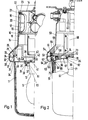
- a lamp housing 10 is composed of a lamp housing 10 and a lamp part 11 connected to it, in which a lamp 12 is held on a base 13.
- the lamp housing 10 is pot-shaped and has in the area of its tofpboden 14 in the wall 15 an opening 16 into which an insert 17 is inserted, which corresponds to the insertion of the lamp according to DE-OS 34 12 395.
- the opening 16 in the wall 15 is surrounded by an inwardly ⁇ ffnun g sstut- zen 10, is molded onto its inner edge an L-shaped projection 19, a U-shape forming the legs with the opening piece 18, the open side shows outside.
- the opening 16 is closed by a cover 20 which has a circumferential groove 21 into which an O-ring 22 is inserted, which in the closed state comes to rest on the edge of the L-shaped projection 19.
- a bar 23 is formed on its peripheral edge, which engages in the open U of the projection 19.
- the free edge of the lamp housing 10 extends frusto-conically and terminates into two preliminary sprin g ends of cylindrical projections 24 and 25 axially concentrically associated with one another and of which the inner extension 25 has a circumferential groove 26 created in which a seal 27 is.
- Lam p enteil 11a Connected to the light housing 10 is of the Lam p enteil 11a.
- This includes a lamp cover 11, which is cup-shaped and made of transparent material. It is at its free edge with one End plate 28 closed.
- This end plate 28 has an opening 29 in its central region and two cylindrical plate extensions 30 and 31 on the outer edge circumference, which project in the axial direction from the lamp cover 11 and are assigned concentrically to one another; the diameter of the inner plate extension 31 corresponds to the diameter of the extension 25 and the diameter of the outer plate extension 30 corresponds to the extension 24, so that in the assembled state both pairs of extensions 31/25 and 30/24 are aligned with one another and thus abut one another.
- the plate extension 31 is longer than the plate extension 30 and it engages in the groove 26 and presses there on the seal 27 to seal the inner region of the lamp housing 10.
- the two outer extensions 30 and 24 have two inclined surfaces 32 and 33, which are together work together for additional sealing and guidance.
- the end plate 28 has a circumferential groove 34 into which the edge of the lamp cover 11 is inserted and fastened, preferably glued.
- the lamp cover 11 and the end plate 28 together form a unit that can be manufactured in the factory.
- the connection between the light housing 10 and the Lam p enabdeckun g 11 with the end plate 28 takes a seites means of a hinge, so that the lamp cover 11 can be pivoted with the end plate 28 together by the lamp housing 10, and on the other hand by means of screw connections (see also Figure 3 and 4) be attached to it.
- the hinge joint is not shown since hinge joints are known per se.
- a support plate 36 is inserted like a bayonet. This has both sides to their planar extension tubular connection piece 37 and 38, of which the longer nozzle 37 g inside the Lampenabeckun engages 11, so that both nozzles 37 and 38 comprises of the collar 35th Between the outer surface of the socket 37 and the inner surface of the collar 35 there is a round seal 39, which also serves to seal the interior of the lamp cover g .
- the socket 38 is provided with a radially outwardly extending flange 40, which abuts against the surface of the end plate 28 facing away from the inside of the lamp cover and thus the support plate 36 with the socket 37 and 38 in connection with the bayonet fitting is known and therefore not shown - fixed and clamped to the end plate 28.
- the lamp base 13, in which the lamp 12 is accommodated, is fastened to the support plate 36 by means of screw connections 41.
- a nose 42 is formed, which engages in a slot 43; the nose 42 and the slot 43 serve as a distinctive device in the form that the nose can only engage in the slot 43 in a certain direction. This is because - seen parallel to the surface extension of the support plate 36 - the length of the nose is greater than its width or its thickness and moreover the width of the slot is adapted to the thickness of the nose 42.
- the Fi g . 2 shows another embodiment of the invention.
- the lamp has a lamp housing 50 and connected to this Lampenabdeckun g 51.
- the projection 54 has a relation to the groove 26 recessed groove 55 into which an Cavity seal 56 is used.
- the projection 54 also has a shoulder 57, on which a holding plate 58 is placed and fastened to it by means of screw connections 59.
- the holding plate 58 serves to hold some components 60 of the lamp housing for supplying the lamp 61, which can be the same as the lamp 12.
- lamp cover extensions 62 and 63 are formed, which essentially correspond to the plate extensions 30 and 31.
- the Lampenabdeckun g sfortsatz 63 is longer than the appendage 62 and it cooperates with the seal 56 together insofar as he is partially engages with its free edge into the interior of the groove 55 is pressed against the seal 56th
- the lamp cover extension 62 is designed in the same way as the extension 30 with the inclined surfaces which cooperate with inclined surfaces on the projection 53 and thus have an additional sealing effect and guidance.
- the lamp cover extension 63 there are a plurality of depressions 64 which are evenly distributed on the circumference, into each of which a nose 65 on a reflector 36 can be latched in the manner of a bayonet lock.
- the reflector 66 has a reflector region 67, on the outer edge of which a cylindrical collar 68 is formed, which carries the lugs 65 on its outer circumference or on its free edge.
- a seal 69 is again located between the outer surface of the collar 68 and the inner surface of the extension 63.
- the reflector region 67 namely in the middle, there is a recessed section 70, on which the base 71, which corresponds to the base 13, is fastened by means of screw connections 72 is.
- the reflector 66 thus forms the end plate for the lamp cover 51; it thus corresponds to the end plate 28, whereby the lamp cover 51 forms a removable unit with the reflector 66. So that the reflector 66 is correctly inserted into the lamp cover 51 and correct assignment of the lamp cover to the relector 66 is ensured, the reflector 66 has on its side opposite the reflection surface an elongated nose 73 which is formed by a protrusion 74 formed on the holding plate 58 not visible slot cooperates.
- the reflector 66 forms, together with the lamp cover 51, a unit which can be pivotably attached to the lamp housing 50 in order to replace the lamp and can be fixed to the lamp housing 50 by means of screws. While the lamp can be easily changed by taking out 12 of the support plate 36 in the arrangement of Fig. 1, g is in the embodiment of Fi. 2 required to remove the reflector 66 to replace the lamp 61 after the lamp part has been folded down.
- the bases 13 and 71 are fastened to the support plate 36 and the reflector 66 with the screw connections 41 and 72.
- a channel 81 which is open into the lamp cover 11 and is externally delimited by the support plate 36 or the section 70.
- formed 82 which is molded by mold resin 83 and 84, whereby in the region of the base 13 and 71 a seal and thus a Schwadendichti g ness effected.
- FIG. 3 shows in section a connection of lamp cover 90 with a lamp housing 91.
- the free edge 92 of the lamp housing is widened and has a U-shaped circumferential groove 93, in the groove base 94 of which a seal is inserted.
- the lamp cover 90 has, in the immediate vicinity of the free edge, an outwardly extending bend 95, as a result of which a radially extending outer shoulder 96 is formed.
- a fastening ring 97 which has an L-shaped profile in cross section, the shorter leg 98 of which forms a radially extending inner shoulder 99, which corresponds to the shoulder 96 on the lamp cover 90, so that the Paragraph 99 against paragraph 96 then comes into play when the ring 97 is tightened against the free edge 29 of the lamp housing by means of the screw-nut connections 100 which are distributed around the circumference.
- the area 101 between the offset 95 and the edge 102 is dimensioned such that the edge 102 presses against the seal 94 in the assembled state and thus a swath-tight Sealing between the edge 102 and the seal 94 is effected.
- the screw Mutternverbindun g 100 has a bolt 103 which is screwed into a free edge 92 inserted into the threaded sleeve 104, and indeed such that the bolt 103 can not be completely unscrewed from the threaded bushing 104th
- keyhole-like recesses 105 are provided, which have a section which is dimensioned such that the head 106 of the bolt 103 fits through, and a narrowed section, the width of which corresponds to the diameter of the bolt region of the bolt 103; this allows the ring to be brought against the edge 92, the screw heads 106 penetrating the larger diameter region of the passage or passage 105; then the ring is rotated together with the lamp cover 90 until the shaft of the screw bolt 103 reaches the region of reduced thickness, in which case the ring or the lamp cover can be screwed against the lamp housing.
- the lamp housing 91 has in a manner similar to the lamp housing 91 of Figure 3 a widened border 92 with the groove 93 and a gasket inserted into the groove 93 111, which, in contrast to the seal 94 according to FIG. 3, projects beyond the free edge surface of the edge 92.
- the free edge of the lamp cover 110 has an outwardly facing strip 112 which is inserted into the recess 113 of a ring 114.
- These Recess 114 is widened towards its base, so that a shoulder 115 is formed, behind which the nose 112 engages.
- FIGS. 3 and 4 only sectional views of the connection of the lamp housing with the lamp cover are shown.
- the parts drawn there are also provided in the embodiments according to FIGS. 3 and 4.
- the cover plate could be provided in the area of the offset 95 and the reflector could be attached to the inner surface of the ring 114 in the embodiment according to FIG.
Landscapes
- Engineering & Computer Science (AREA)
- General Engineering & Computer Science (AREA)
- Arrangement Of Elements, Cooling, Sealing, Or The Like Of Lighting Devices (AREA)
Applications Claiming Priority (2)
| Application Number | Priority Date | Filing Date | Title |
|---|---|---|---|
| DE3528469 | 1985-08-08 | ||
| DE19853528469 DE3528469A1 (de) | 1985-08-08 | 1985-08-08 | Leuchte |
Publications (2)
| Publication Number | Publication Date |
|---|---|
| EP0211355A2 true EP0211355A2 (fr) | 1987-02-25 |
| EP0211355A3 EP0211355A3 (fr) | 1989-02-01 |
Family
ID=6278029
Family Applications (1)
| Application Number | Title | Priority Date | Filing Date |
|---|---|---|---|
| EP86110296A Withdrawn EP0211355A3 (fr) | 1985-08-08 | 1986-07-25 | Dispositif d'éclairage |
Country Status (2)
| Country | Link |
|---|---|
| EP (1) | EP0211355A3 (fr) |
| DE (1) | DE3528469A1 (fr) |
Cited By (1)
| Publication number | Priority date | Publication date | Assignee | Title |
|---|---|---|---|---|
| DE19628756A1 (de) * | 1996-07-17 | 1998-01-22 | Abb Patent Gmbh | Beleuchtungseinsatz |
Citations (7)
| Publication number | Priority date | Publication date | Assignee | Title |
|---|---|---|---|---|
| US1741965A (en) * | 1928-03-27 | 1929-12-31 | William H Yates | Electric-lamp fixture |
| DE859921C (de) * | 1941-05-08 | 1952-12-18 | Schanzenbach & Co Ges Mit Besc | Explosionssichere elektrische Leuchte |
| DE2250197A1 (de) * | 1972-10-13 | 1974-04-25 | Westfaelische Metall Industrie | Lampenfassung fuer leuchten, insbesondere bootsleuchten |
| DE2531968A1 (de) * | 1975-07-17 | 1977-02-03 | Stahl Niederlassung Kuenzelsau | Explosionsgeschuetzte leuchte |
| FR2383393A1 (fr) * | 1977-03-08 | 1978-10-06 | Martin Et Lunel Sa | Hublot d'eclairage |
| GB2089489A (en) * | 1980-12-15 | 1982-06-23 | Keene Corp | A lighting fitting |
| EP0139075A1 (fr) * | 1983-10-25 | 1985-05-02 | Schydlo, Martin Thadäus | Ensemble projecteur |
Family Cites Families (10)
| Publication number | Priority date | Publication date | Assignee | Title |
|---|---|---|---|---|
| DE1073096B (de) * | 1960-01-14 | Siemens-Schuckertwerke Aktiengesellschaft, Berlin Und Erlangen | Dichtungsvorrichtung fur staubdichte Leuchten | |
| DE1613174U (de) * | 1950-01-24 | 1950-09-14 | Hermann Wilden | Als tiefstrahler ausgebildete leuchte. |
| DE813733C (de) * | 1950-05-10 | 1951-09-17 | Walter Roehrich | Sicherheitsleuchte |
| DE1796299U (de) * | 1959-06-11 | 1959-09-24 | Schanzenbach & Co Gmbh | Schlagwettergeschuetzte leuchte mit gluehlampe. |
| DE2052416A1 (de) * | 1970-10-26 | 1972-05-04 | C A Schaefer Kg | Leuchtengehäuse |
| DE8115814U1 (de) * | 1981-05-27 | 1982-11-11 | Robert Bosch Gmbh, 7000 Stuttgart | Scheinwerfer fuer kraftfahrzeuge |
| DE8130135U1 (de) * | 1981-10-15 | 1982-04-15 | Gustav Markus Metallwarenfabrik, 4770 Soest | Spritzwassergeschuetzte spiegelleuchte |
| DE8220282U1 (de) * | 1982-07-16 | 1983-12-29 | Robert Bosch Gmbh, 7000 Stuttgart | Leuchte fuer fahrzeuge, insbesondere blinkleuchte fuer kraftfahrzeuge |
| DE8333561U1 (de) * | 1983-11-23 | 1984-02-16 | Bösha GmbH & Co KG, 4780 Lippstadt | Langfeldleuchte fuer den einsatz in schlagwetter- und explosionsgeschuetzten bereichen |
| DE8508487U1 (de) * | 1985-03-22 | 1985-05-09 | Westfälische Metall Industrie KG Hueck & Co, 4780 Lippstadt | Fahrzeugleuchte |
-
1985
- 1985-08-08 DE DE19853528469 patent/DE3528469A1/de not_active Withdrawn
-
1986
- 1986-07-25 EP EP86110296A patent/EP0211355A3/fr not_active Withdrawn
Patent Citations (7)
| Publication number | Priority date | Publication date | Assignee | Title |
|---|---|---|---|---|
| US1741965A (en) * | 1928-03-27 | 1929-12-31 | William H Yates | Electric-lamp fixture |
| DE859921C (de) * | 1941-05-08 | 1952-12-18 | Schanzenbach & Co Ges Mit Besc | Explosionssichere elektrische Leuchte |
| DE2250197A1 (de) * | 1972-10-13 | 1974-04-25 | Westfaelische Metall Industrie | Lampenfassung fuer leuchten, insbesondere bootsleuchten |
| DE2531968A1 (de) * | 1975-07-17 | 1977-02-03 | Stahl Niederlassung Kuenzelsau | Explosionsgeschuetzte leuchte |
| FR2383393A1 (fr) * | 1977-03-08 | 1978-10-06 | Martin Et Lunel Sa | Hublot d'eclairage |
| GB2089489A (en) * | 1980-12-15 | 1982-06-23 | Keene Corp | A lighting fitting |
| EP0139075A1 (fr) * | 1983-10-25 | 1985-05-02 | Schydlo, Martin Thadäus | Ensemble projecteur |
Cited By (1)
| Publication number | Priority date | Publication date | Assignee | Title |
|---|---|---|---|---|
| DE19628756A1 (de) * | 1996-07-17 | 1998-01-22 | Abb Patent Gmbh | Beleuchtungseinsatz |
Also Published As
| Publication number | Publication date |
|---|---|
| DE3528469A1 (de) | 1987-02-19 |
| EP0211355A3 (fr) | 1989-02-01 |
Similar Documents
| Publication | Publication Date | Title |
|---|---|---|
| DE19501327A1 (de) | Schutzrohrleuchte | |
| DE3004446A1 (de) | Fahrzeugscheinwerfer | |
| EP0211355A2 (fr) | Dispositif d'éclairage | |
| EP0392089A2 (fr) | Dispositif de fermeture d'une extrémité de câble | |
| DE10013086A1 (de) | Einbauleuchte mit einem domförmigen Reflektor | |
| DE19546370C2 (de) | Kraftfahrzeugscheinwerfer mit einem Scheinwerferkörper und einer Lampenfassungsabdeckung | |
| EP3601883B1 (fr) | Appareil d'éclairage à tête lumineuse réglable | |
| DE4121575C1 (fr) | ||
| DE3605209C2 (fr) | ||
| EP0301236A2 (fr) | Projecteur étanche aux jets d'eau | |
| DE2915778C2 (de) | Raumfachwerk, insbesondere Lichtrohrsystem | |
| EP0195980A2 (fr) | Dispositif de fixation pour support de lampe | |
| DE4316271A1 (de) | Beleuchtungsvorrichtung | |
| DE922725C (de) | Wasserdichte Fassung fuer elektrische Leuchtroehren mit Zweistiftsockel | |
| EP0705731A2 (fr) | Feu de véhicule en particulier pour plaque d'immatriculation | |
| DE6940173U (de) | Einrichtung zur deckenbefestigung von langfeldleuchten | |
| DE2616958A1 (de) | Strahler | |
| DE2450579A1 (de) | Vorrichtung zum befestigen eines leuchtenunterteiles an der tragschiene eines lichtbandes oder an einem leuchtengehaeuse | |
| EP0784165B1 (fr) | Dispositif tendeur de câble | |
| EP0961077A2 (fr) | Dispositif porte-lampe pour luminaire à bras articulés comprenant une tête d'éclairage | |
| EP0638972A1 (fr) | Boîte d'installation électrique pour montage en affleurement | |
| DE2164204A1 (de) | Kupplung für eine Lampe in einem Lampenhalter | |
| DE19609829C2 (de) | Glühlampenfassung | |
| DE1069781B (fr) | ||
| CH659534A5 (en) | Label device with clamping holder and label plate |
Legal Events
| Date | Code | Title | Description |
|---|---|---|---|
| PUAI | Public reference made under article 153(3) epc to a published international application that has entered the european phase |
Free format text: ORIGINAL CODE: 0009012 |
|
| AK | Designated contracting states |
Kind code of ref document: A2 Designated state(s): BE DE FR GB NL SE |
|
| PUAL | Search report despatched |
Free format text: ORIGINAL CODE: 0009013 |
|
| RAP1 | Party data changed (applicant data changed or rights of an application transferred) |
Owner name: ABB CEAG LICHT- UND STROMVERSORGUNGSTECHNIK GMBH |
|
| AK | Designated contracting states |
Kind code of ref document: A3 Designated state(s): BE DE FR GB NL SE |
|
| 17P | Request for examination filed |
Effective date: 19890316 |
|
| 17Q | First examination report despatched |
Effective date: 19900921 |
|
| STAA | Information on the status of an ep patent application or granted ep patent |
Free format text: STATUS: THE APPLICATION IS DEEMED TO BE WITHDRAWN |
|
| 18D | Application deemed to be withdrawn |
Effective date: 19921024 |
|
| RIN1 | Information on inventor provided before grant (corrected) |
Inventor name: PLOEGER, CORNELIUS Inventor name: NEUMANN, REINHARD |