EP0211355A2 - Lighting fixture - Google Patents
Lighting fixture Download PDFInfo
- Publication number
- EP0211355A2 EP0211355A2 EP86110296A EP86110296A EP0211355A2 EP 0211355 A2 EP0211355 A2 EP 0211355A2 EP 86110296 A EP86110296 A EP 86110296A EP 86110296 A EP86110296 A EP 86110296A EP 0211355 A2 EP0211355 A2 EP 0211355A2
- Authority
- EP
- European Patent Office
- Prior art keywords
- lamp
- lamp cover
- cover
- support plate
- base
- Prior art date
- Legal status (The legal status is an assumption and is not a legal conclusion. Google has not performed a legal analysis and makes no representation as to the accuracy of the status listed.)
- Withdrawn
Links
Images

Classifications
-
- F—MECHANICAL ENGINEERING; LIGHTING; HEATING; WEAPONS; BLASTING
- F21—LIGHTING
- F21S—NON-PORTABLE LIGHTING DEVICES; SYSTEMS THEREOF; VEHICLE LIGHTING DEVICES SPECIALLY ADAPTED FOR VEHICLE EXTERIORS
- F21S8/00—Lighting devices intended for fixed installation
- F21S8/04—Lighting devices intended for fixed installation intended only for mounting on a ceiling or the like overhead structures
-
- F—MECHANICAL ENGINEERING; LIGHTING; HEATING; WEAPONS; BLASTING
- F21—LIGHTING
- F21V—FUNCTIONAL FEATURES OR DETAILS OF LIGHTING DEVICES OR SYSTEMS THEREOF; STRUCTURAL COMBINATIONS OF LIGHTING DEVICES WITH OTHER ARTICLES, NOT OTHERWISE PROVIDED FOR
- F21V25/00—Safety devices structurally associated with lighting devices
- F21V25/12—Flameproof or explosion-proof arrangements
-
- F—MECHANICAL ENGINEERING; LIGHTING; HEATING; WEAPONS; BLASTING
- F21—LIGHTING
- F21V—FUNCTIONAL FEATURES OR DETAILS OF LIGHTING DEVICES OR SYSTEMS THEREOF; STRUCTURAL COMBINATIONS OF LIGHTING DEVICES WITH OTHER ARTICLES, NOT OTHERWISE PROVIDED FOR
- F21V31/00—Gas-tight or water-tight arrangements
Definitions
- the invention relates to a lamp, the type listed in the preamble of claim 1.
- Such a lamp has become known from DE-OS 34 12 395.
- a seal is provided between the lamp housing and the lamp cover, as a result of which the lamp is overall impermeable to steam.
- the space inside the lamp cover is not restricted breathing close by itself and when the lamp needs to be replaced, the lamp cover is removed and the lamp can then be removed from the g on the lamps ephaseuse remaining base.
- the housing which accommodates the components for power supply to the lamp, even met the requirement "Schwadendichti g ness".
- a similar, fireproof light with an incandescent lamp has become known from DE-GM 17 96 299.
- a support plate is firmly connected to the lamp housing, to which the lamp cover is attached. Overall, the lamp is vapor-tight; after removing the lamp cover, the lamp remains on the lamp housing.
- the object of the invention is to provide a luminaire of the type mentioned, in which additionally the space delimited by the lamp cover is itself vapor-tight.
- the lamp consists of two parts, namely a lamp part, which is formed from the cup-shaped lamp cover, to which the end plate is attached, the end plate itself supporting the base for the lamp, which means that the lamp part can be embodied in a vapor-tight manner, and an optical assembly which receives the components for supply to the lamp and with which the Lam can be p enteil connected in a simple manner.
- a lamp part which is formed from the cup-shaped lamp cover, to which the end plate is attached
- the end plate itself supporting the base for the lamp
- an optical assembly which receives the components for supply to the lamp and with which the Lam can be p enteil connected in a simple manner.
- the base is fastened to the inner surface of the support plate by means of screw connections which pass through the support plate.
- this screw connections or via the holes, through which engage the screws no steam can get in the interior 'of the lamp part to the inside, is see e-on the inner surface of the support plate a G discernharzabdichtung according to the characterizing feature of claim 5 prior g.
- a vapor tightness is achieved in the area of the attachment of the base to the support plate.
- a further embodiment of the invention can be found in claims 6 to 8. Thereafter, the end plate itself is designed as a reflector, which in its entirety can be removed from the lamp cover in order to replace the lamp.
- the characterizing feature of claim 8 to obtain a Schwadendichti g ness sealing with casting resin is provided.
- connection of the Lam p enteils with the light part is carried out in accordance with the characterizing features of claims 10 to 14.
- the characterizing features of claim 10 or 11 be not avoid the problem of a relatively large voltage within the lamp cover in the region of the screws.
- a particularly advantageous improvement is achieved in that an additional ring is provided according to the characterizing part of claim 12 serves to hold the lamp part on the lamp housing and is used to clamp the lamp cover against the lamp housing.
- a simplified assembly of this ring on the lamp housing can be found in the features of claim 13 and the features of claim 14 can be provided for fastening the lamp cover on the ring.
- a lamp housing 10 is composed of a lamp housing 10 and a lamp part 11 connected to it, in which a lamp 12 is held on a base 13.
- the lamp housing 10 is pot-shaped and has in the area of its tofpboden 14 in the wall 15 an opening 16 into which an insert 17 is inserted, which corresponds to the insertion of the lamp according to DE-OS 34 12 395.
- the opening 16 in the wall 15 is surrounded by an inwardly ⁇ ffnun g sstut- zen 10, is molded onto its inner edge an L-shaped projection 19, a U-shape forming the legs with the opening piece 18, the open side shows outside.
- the opening 16 is closed by a cover 20 which has a circumferential groove 21 into which an O-ring 22 is inserted, which in the closed state comes to rest on the edge of the L-shaped projection 19.
- a bar 23 is formed on its peripheral edge, which engages in the open U of the projection 19.
- the free edge of the lamp housing 10 extends frusto-conically and terminates into two preliminary sprin g ends of cylindrical projections 24 and 25 axially concentrically associated with one another and of which the inner extension 25 has a circumferential groove 26 created in which a seal 27 is.
- Lam p enteil 11a Connected to the light housing 10 is of the Lam p enteil 11a.
- This includes a lamp cover 11, which is cup-shaped and made of transparent material. It is at its free edge with one End plate 28 closed.
- This end plate 28 has an opening 29 in its central region and two cylindrical plate extensions 30 and 31 on the outer edge circumference, which project in the axial direction from the lamp cover 11 and are assigned concentrically to one another; the diameter of the inner plate extension 31 corresponds to the diameter of the extension 25 and the diameter of the outer plate extension 30 corresponds to the extension 24, so that in the assembled state both pairs of extensions 31/25 and 30/24 are aligned with one another and thus abut one another.
- the plate extension 31 is longer than the plate extension 30 and it engages in the groove 26 and presses there on the seal 27 to seal the inner region of the lamp housing 10.
- the two outer extensions 30 and 24 have two inclined surfaces 32 and 33, which are together work together for additional sealing and guidance.
- the end plate 28 has a circumferential groove 34 into which the edge of the lamp cover 11 is inserted and fastened, preferably glued.
- the lamp cover 11 and the end plate 28 together form a unit that can be manufactured in the factory.
- the connection between the light housing 10 and the Lam p enabdeckun g 11 with the end plate 28 takes a seites means of a hinge, so that the lamp cover 11 can be pivoted with the end plate 28 together by the lamp housing 10, and on the other hand by means of screw connections (see also Figure 3 and 4) be attached to it.
- the hinge joint is not shown since hinge joints are known per se.
- a support plate 36 is inserted like a bayonet. This has both sides to their planar extension tubular connection piece 37 and 38, of which the longer nozzle 37 g inside the Lampenabeckun engages 11, so that both nozzles 37 and 38 comprises of the collar 35th Between the outer surface of the socket 37 and the inner surface of the collar 35 there is a round seal 39, which also serves to seal the interior of the lamp cover g .
- the socket 38 is provided with a radially outwardly extending flange 40, which abuts against the surface of the end plate 28 facing away from the inside of the lamp cover and thus the support plate 36 with the socket 37 and 38 in connection with the bayonet fitting is known and therefore not shown - fixed and clamped to the end plate 28.
- the lamp base 13, in which the lamp 12 is accommodated, is fastened to the support plate 36 by means of screw connections 41.
- a nose 42 is formed, which engages in a slot 43; the nose 42 and the slot 43 serve as a distinctive device in the form that the nose can only engage in the slot 43 in a certain direction. This is because - seen parallel to the surface extension of the support plate 36 - the length of the nose is greater than its width or its thickness and moreover the width of the slot is adapted to the thickness of the nose 42.
- the Fi g . 2 shows another embodiment of the invention.
- the lamp has a lamp housing 50 and connected to this Lampenabdeckun g 51.
- the projection 54 has a relation to the groove 26 recessed groove 55 into which an Cavity seal 56 is used.
- the projection 54 also has a shoulder 57, on which a holding plate 58 is placed and fastened to it by means of screw connections 59.
- the holding plate 58 serves to hold some components 60 of the lamp housing for supplying the lamp 61, which can be the same as the lamp 12.
- lamp cover extensions 62 and 63 are formed, which essentially correspond to the plate extensions 30 and 31.
- the Lampenabdeckun g sfortsatz 63 is longer than the appendage 62 and it cooperates with the seal 56 together insofar as he is partially engages with its free edge into the interior of the groove 55 is pressed against the seal 56th
- the lamp cover extension 62 is designed in the same way as the extension 30 with the inclined surfaces which cooperate with inclined surfaces on the projection 53 and thus have an additional sealing effect and guidance.
- the lamp cover extension 63 there are a plurality of depressions 64 which are evenly distributed on the circumference, into each of which a nose 65 on a reflector 36 can be latched in the manner of a bayonet lock.
- the reflector 66 has a reflector region 67, on the outer edge of which a cylindrical collar 68 is formed, which carries the lugs 65 on its outer circumference or on its free edge.
- a seal 69 is again located between the outer surface of the collar 68 and the inner surface of the extension 63.
- the reflector region 67 namely in the middle, there is a recessed section 70, on which the base 71, which corresponds to the base 13, is fastened by means of screw connections 72 is.
- the reflector 66 thus forms the end plate for the lamp cover 51; it thus corresponds to the end plate 28, whereby the lamp cover 51 forms a removable unit with the reflector 66. So that the reflector 66 is correctly inserted into the lamp cover 51 and correct assignment of the lamp cover to the relector 66 is ensured, the reflector 66 has on its side opposite the reflection surface an elongated nose 73 which is formed by a protrusion 74 formed on the holding plate 58 not visible slot cooperates.
- the reflector 66 forms, together with the lamp cover 51, a unit which can be pivotably attached to the lamp housing 50 in order to replace the lamp and can be fixed to the lamp housing 50 by means of screws. While the lamp can be easily changed by taking out 12 of the support plate 36 in the arrangement of Fig. 1, g is in the embodiment of Fi. 2 required to remove the reflector 66 to replace the lamp 61 after the lamp part has been folded down.
- the bases 13 and 71 are fastened to the support plate 36 and the reflector 66 with the screw connections 41 and 72.
- a channel 81 which is open into the lamp cover 11 and is externally delimited by the support plate 36 or the section 70.
- formed 82 which is molded by mold resin 83 and 84, whereby in the region of the base 13 and 71 a seal and thus a Schwadendichti g ness effected.
- FIG. 3 shows in section a connection of lamp cover 90 with a lamp housing 91.
- the free edge 92 of the lamp housing is widened and has a U-shaped circumferential groove 93, in the groove base 94 of which a seal is inserted.
- the lamp cover 90 has, in the immediate vicinity of the free edge, an outwardly extending bend 95, as a result of which a radially extending outer shoulder 96 is formed.
- a fastening ring 97 which has an L-shaped profile in cross section, the shorter leg 98 of which forms a radially extending inner shoulder 99, which corresponds to the shoulder 96 on the lamp cover 90, so that the Paragraph 99 against paragraph 96 then comes into play when the ring 97 is tightened against the free edge 29 of the lamp housing by means of the screw-nut connections 100 which are distributed around the circumference.
- the area 101 between the offset 95 and the edge 102 is dimensioned such that the edge 102 presses against the seal 94 in the assembled state and thus a swath-tight Sealing between the edge 102 and the seal 94 is effected.
- the screw Mutternverbindun g 100 has a bolt 103 which is screwed into a free edge 92 inserted into the threaded sleeve 104, and indeed such that the bolt 103 can not be completely unscrewed from the threaded bushing 104th
- keyhole-like recesses 105 are provided, which have a section which is dimensioned such that the head 106 of the bolt 103 fits through, and a narrowed section, the width of which corresponds to the diameter of the bolt region of the bolt 103; this allows the ring to be brought against the edge 92, the screw heads 106 penetrating the larger diameter region of the passage or passage 105; then the ring is rotated together with the lamp cover 90 until the shaft of the screw bolt 103 reaches the region of reduced thickness, in which case the ring or the lamp cover can be screwed against the lamp housing.
- the lamp housing 91 has in a manner similar to the lamp housing 91 of Figure 3 a widened border 92 with the groove 93 and a gasket inserted into the groove 93 111, which, in contrast to the seal 94 according to FIG. 3, projects beyond the free edge surface of the edge 92.
- the free edge of the lamp cover 110 has an outwardly facing strip 112 which is inserted into the recess 113 of a ring 114.
- These Recess 114 is widened towards its base, so that a shoulder 115 is formed, behind which the nose 112 engages.
- FIGS. 3 and 4 only sectional views of the connection of the lamp housing with the lamp cover are shown.
- the parts drawn there are also provided in the embodiments according to FIGS. 3 and 4.
- the cover plate could be provided in the area of the offset 95 and the reflector could be attached to the inner surface of the ring 114 in the embodiment according to FIG.
Abstract
Description
Die Erfindung betrifft eine Leuchte, der im Oberbegriff des Anspruches 1 aufgeführten Art.The invention relates to a lamp, the type listed in the preamble of claim 1.
Eine derartige Leuchte ist aus der DE-OS 34 12 395 bekannt geworden. Zwischen dem Leuchtengehäuse und der Lampenabdeckung ist eine Dichtung vorgesehen, wodurch die Leuchte insgesamt schwadendicht ist. Der Raum innerhalb der Lampenabdeckung jedoch ist für sich nicht schwadendicht und wenn die Lampe ausgewechselt werden muß, wird die Lampenabdeckung entfernt und die Lampe kann dann vom am Lampengehäuse verbleibenden Sockel abmontiert werden. Das Leuchtengehäuse, das die Komponenten zur Stromversorgung der Lampe aufnimmt, erfüllt selbst die Vorschrift "Schwadendichtigkeit".Such a lamp has become known from DE-OS 34 12 395. A seal is provided between the lamp housing and the lamp cover, as a result of which the lamp is overall impermeable to steam. The space inside the lamp cover, however, is not restricted breathing close by itself and when the lamp needs to be replaced, the lamp cover is removed and the lamp can then be removed from the g on the lamps ehäuse remaining base. The housing, which accommodates the components for power supply to the lamp, even met the requirement "Schwadendichti g ness".
Eine ähnliche, schlagwettergeschützte Leuchte mit einer Glühlampe ist aus dem DE-GM 17 96 299 bekanntgeworden. Dort ist mit dem Leuchtengehäuse eine Tragplatte fest verbunden, an der die Lampenabdeckung befestigt ist. Insgesamt ist die Leuchte schwadendicht; nach dem Abnehmen der Lampenabdeckung verbleibt die Lampe am Leuchtengehäuse.A similar, fireproof light with an incandescent lamp has become known from DE-GM 17 96 299. There, a support plate is firmly connected to the lamp housing, to which the lamp cover is attached. Overall, the lamp is vapor-tight; after removing the lamp cover, the lamp remains on the lamp housing.
Aufgabe der Erfindung ist es, eine Leuchte der eingangs genannten Art zu schaffen, bei der zusätzlich auch der durch die Lampenabdeckung begrenzte Raum für sich schwadendicht ist.The object of the invention is to provide a luminaire of the type mentioned, in which additionally the space delimited by the lamp cover is itself vapor-tight.
Diese Aufgabe wird erfindungsgemäß gelöst durch die kennzeichnenden Merkmale des Anspruches 1.This object is achieved according to the invention by the characterizing features of claim 1.
Erfindungsgemäß besteht die Leuchte also aus zwei Teilen, nämlich einem Lampenteil, das aus der topfförmigen Lampenabdeckung gebildet ist, an der die Abschlußplatte befestigt ist, wobei die Abschlußplatte selbst den Sockel für die Lampe trägt, wodurch das Lampenteil für sich schwadendicht ausgebildet sein kann, und aus einem Leuchtengehäuse, das die Komponenten zur Versorgung der Lampe aufnimmt und mit dem der Lampenteil auf einfache Weise verbunden werden kann. Damit sind beide Teile für sich schwadendicht und zum Auswechseln der Lampe ist eine vollständige Demontage der Leuchte von ihrer Halterung nicht mehr erforderlich; es genügt dann nur noch, den Lampenteil von dem Leuchtengehäuse zu demontieren. Damit die Lampe leicht ausgewechselt werden kann, ist gemäß kennzeichnendem Teil des Anspruches 2 an der Abschlußplatte eine Tragplatte bspw. mittels eines Bajonettverschlusses befestigbar. Dabei besitzt die Abschlußplatte eine Durchbrechung, durch die die Tragplatte hindurchgreift, bzw. in die die Tragplatte eingesetzt ist, so daß zum Auswechseln der Lampe lediglich die Tragplatte aus der Abschlußplatte herausge-nommen werden muß.According to the invention, the lamp consists of two parts, namely a lamp part, which is formed from the cup-shaped lamp cover, to which the end plate is attached, the end plate itself supporting the base for the lamp, which means that the lamp part can be embodied in a vapor-tight manner, and an optical assembly which receives the components for supply to the lamp and with which the Lam can be p enteil connected in a simple manner. This means that both parts are vapor-tight and to replace the lamp it is no longer necessary to completely remove the lamp from its holder; it is then only sufficient to remove the lamp part from the lamp housing. So that the lamp can be easily replaced, is a support plate bs p w according to the characterizing part of claim 2 on the end plate. attachable with a bayonet catch. The end plate has an opening, through which engages the support plate, and in which the support plate is inserted, so that in order to replace the lamp, only the support plate from the end plate out e-g taken to be.
Die Befestigung des Sockels auf der Innenfläche der Tragplatte erfolgt mittels Schraubenverbindungen, die die Tragplatte durchgreifen. Damit über diese Schraubenverbindungen bzw. über die Bohrungen, durch die die Schrauben hindurchgreifen, keine Schwaden nach innen ins Innere 'des Lampenteils hineingelangen können, ist auf der Innenfläche der Tragplatte eine Gießharzabdichtung gemäß kennzeichnendem Merkmal des Anspruches 5 vorge-sehen. Dadurch wird eine Schwadendichtigkeit im Bereich der Befestigung des Sockels an der Tragplatte erreicht.The base is fastened to the inner surface of the support plate by means of screw connections which pass through the support plate. Thus this screw connections or via the holes, through which engage the screws, no steam can get in the interior 'of the lamp part to the inside, is see e-on the inner surface of the support plate a Gießharzabdichtung according to the characterizing feature of claim 5 prior g. As a result, a vapor tightness is achieved in the area of the attachment of the base to the support plate.
Eine weitere Ausgestaltung der Erfindung ist den Ansprüchen 6 bis 8 zu entnehmen. Danach ist die Abschlußplatte selbst als Reflektor ausgebildet, der in seiner Gesamtheit aus der Lampenabdeckung herausgenommen werden kann, um die Lampe auszutauschen. Auch hier ist wieder gemäß kennzeichnendem Merkmal des Anspruches 8 zur Erzielung einer Schwadendichtigkeit eine Abdichtung mit Gießharz vorgesehen.A further embodiment of the invention can be found in claims 6 to 8. Thereafter, the end plate itself is designed as a reflector, which in its entirety can be removed from the lamp cover in order to replace the lamp. Here again according to the characterizing feature of claim 8 to obtain a Schwadendichti g ness sealing with casting resin is provided.
Zur Sicherstellung der lagerichtigen Montage der Abdeckung, der Tragplatte bzw. des Reflektors sind diejenigen Merkmale vorgesehen, die aus dem kennzeichnenden Teil des Anspruches 9 hervorgehen.To ensure the correct mounting of the cover, the support plate or the reflector, those features are provided that emerge from the characterizing part of claim 9.
Die Verbindung des Lampenteils mit dem Leuchtenteil erfolgt gemäß den kennzeichnenden Merkmalen der Ansprüche 10 bis 14. Dabei wird gemäß den kennzeichnenden Merkmalen des Anspruches 10 bzw. 11 das Problem einer relativ großen Spannung innerhalb der Lampenabdeckung im Bereich der Schrauben nicht zu vermeiden sein. Eine besonders vorteilhafte Verbesserung hierbei wird dadurch erzielt, daß gemäß kennzeichnendem Teil des Anspruches 12 ein zusätzlicher Ring vorgesehen ist, der zur Halterung des Lampenteils an dem Leuchtengehäuse dient und der zum Verspannen der Lampenabdeckung gegen das Leuchtengehäuse verwendet wird. Eine vereinfachte Montage dieses Ringes am Leuchtengehäuse ist den Merkmalen des Anspruches 13 zu entnehmen und zur Befestigung der Lampenabdeckung am Ring können die Merkmale des Anspruches 14 vorgesehen werden.The connection of the Lam p enteils with the light part is carried out in accordance with the characterizing features of
Anhand der Zeichnung, in der einige Ausführungsbeispiele der Erfindung dargestellt sind, sollen die Erfindung sowie weitere vorteilhafte Ausgestaltungen und Verbes- serungen näher erläutert und beschrieben werden.Reference to the drawing, are presented in some embodiments of the invention, the invention and further advantageous embodiments and to im- SERUN g s are explained and described.
Es zeigt:
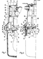
- Figur 1 eine Schnittansicht einer ersten Leuchtenausführung, zur Hälfte gezeichnet,
- Figur 2 eine Schnittansicht einer zweiten Leuchtenausführung, ähnlich der Darstellung der Fig. 1,
- Figur 3 eine Schnittansicht einer Verbindung zwischen dem Leuchtengehäuse und der Lampenabdeckung und
- Figur 4 eine weitere Ausgestaltung einer Verbindung zwischen Leuchtengehäuse und Lampenabdeckung, ähnlich der der Fig. 3, teilweise geschnitten.
- FIG. 1 shows a sectional view of a first lamp version, drawn in half,
- Figure 2 is a sectional view of a second lamp version, similar to the representation of the Fi g . 1,
- Figure 3 is a sectional view of a connection between the lamp housing and the lamp cover and
- Figure 4 shows another embodiment of a connection between the lamp housing and lamp cover, similar to that of Fig. 3, partially cut.
In allen Figuren sind die Schnittansichten nur auf einer Hälfte gezeichnet; sie sind bezüglich der Gehäuseteile im wesentlichen symmetrisch zu der Mittellinie zu denken.In all figures, the sectional views are only drawn on one half; with regard to the housing parts, they are to be considered essentially symmetrical to the center line.
Die Leuchte gemäß Fig. 1 ist aus einem Leuchtengehäuse 10 und einem damit verbundenen Lampenteil 11 zusammengesetzt, in dem eine Lampe 12 an einem Sockel 13 gehaltert ist.1 is composed of a
Das Leuchtengehäuse 10 ist topfförmig ausgebildet und besitzt im Bereich seines Tofpbodens 14 in der Wandung 15 eine Öffnung 16, in die ein Einschub 17 eingeführt ist, der dem Einschub der Leuchte gemäß der DE-OS 34 12 395 entspricht. Die Öffnung 16 in der Wandung 15 ist umgeben von einem nach innen ragenden Öffnungsstut- zen 10, an dessen innerem Rand ein L-förmiger Vorsprung 19 angeformt ist, dessen Schenkel mit dem Öffnungsstutzen 18 eine U-Form bildet, deren offene Seite nach außen weist. Die Öffnung 16 ist mit einem Deckel 20 verschlossen, der eine umlaufende Nut 21 aufweist, in die ein 0-Ring 22 eingelegt ist, der im verschlossenen Zustand auf die Randkante des L-förmigen Vorsprunges 19 zum Anliegen kommt. Zur Führung des Deckels 20 ist an dessen Umfangsrand eine Leiste 23 angeformt, die in das geöffnete U des Vorsprunges 19 eingreift.The
Der freie Rand des Leuchtengehäuses 10 erweitert sich kegelstumpfförmig und endet dabei in zwei axial vor- springenden zylinderförmigen Fortsätzen 24 und 25, die konzentrisch einander zugeordnet sind und von denen der innere Fortsatz 25 eine umlaufende Nut 26 aufweist, in der eine Dichtung 27 angelegt ist.The free edge of the
Mit dem Leuchtengehäuse 10 verbunden ist der Lampenteil 11a. Dieser umfaßt eine Lampenabdeckung 11, die topfförmig ausgebildet ist und aus transparentem Material besteht. Sie ist an ihrem freien Rand mit einer Abschlußplatte 28 verschlossen. Diese Abschlußplatte 28 besitzt in ihrem mittleren Bereich einen Durchbruch 29 und am äußeren Randumfang zwei zylinderförmige Plattenfortsätze 30 und 31, die in axialer Richtung von der Lampenabdeckung 11 vorspringen und konzentrisch einander zugeordnet sind; der Durchmesser des inneren Plattenfortsatzes 31 entspricht dem Durchmesser des Fortsatzes 25 und der Durckmesser des äußeren Plattenfortsatzes 30 dem Fortsatz 24, so daß im montierten Zustand beide Fortsatzpaare 31/25 und 30/24 miteinander fluchten und so gegeneinanderstoßen. Dabei ist der Plattenfortsatz 31 länger als der Plattenfortsatz 30 und er greift in die Nut 26 ein und drückt dort auf die Dichtung 27 zur Abdichtung des inneren Bereiches des Leuchtengehäuses 10. Die beiden äußeren Fortsätze 30 und 24 besitzen zwei Schrägflächen 32 und 33, die miteinander zusammenwirken zur zusätzlichen Abdichtung und zur Führung.Connected to the
Die Abschlußplatte 28 besitzt eine umlaufende Nut 34, in die der Rand der Lampenabdeckung 11 eingesetzt und darin befestigt, vorzugsweise verklebt ist. Damit bilden die Lampenabdeckung 11 und die Abschlußplatte 28 miteinander eine Einheit, die fabrikseitig hergestellt werden kann. Die Verbindung zwischen dem Leuchtengehäuse 10 und der Lampenabdeckung 11 mit der Abschlußplatte 28 erfolgt einerseites mittels eines Scharnieres, so daß die Lampenabdeckung 11 mit der Abschlußplatte 28 gemeinsam vom Leuchtengehäuse 10 abgeschwenkt werden können, und andererseits mittels Schraubenverbindungen (siehe auch Figur 3 und 4) daran befestigt werden. Das Scharniergelenk ist nicht dargestellt, da Scharniergelenke an sich bekannt sind.The
In den Durchbruch 29, der einen stutzenartig ins Innere der Leuchtenabdeckung 11 hineinragenden Kragen 35 aufweist, ist eine Tragplatte 36 bajonettverschlußartig eingesetzt. Diese besitzt beidseitig zu ihrer flächigen Erstreckung rohrförmige Stutzen 37 und 38, von denen der längere Stutzen 37 ins Innere der Lampenabeckung 11 eingreift, so daß beide Stutzen 37 und 38 von dem Kragen 35 umfaßt sind. Zwischen der Außenfläche des Stutzens 37 und der Innenfläche des Kragens 35 befindet sich eine Runddichtung 39, die zusätzlich zur Abdichtung des Inneren der Leuchtenabdeckung dient. Der Stutzen 38 ist mit einem radial nach außen verlaufenden Flansch 40 versehen, der gegen die von der Innenseite der Leuchtenabdeckung abgewandte Fläche der Abschlußplatte 28 im montierten Zustand anschlägt und so die Tragplatte 36 mit den Stutzen 37 und 38 in Verbindung mit dem Bajonettverschluß - der an sich bekannt und daher nicht dargestellt ist - an der Abschlußplatte 28 fixiert und verspannt. An der Tragplatte 36 ist mittels Schraubenverbindungen 41 der Lampensockel 13 befestigt, in dem die Lampe 12 aufgenommen ist.In the opening 29, which has a stutzenarti g protruding into the interior of the
An der Außenfläche der Tragplatte 36 ist eine Nase 42 angeformt, die in einen Schlitz 43 eingreift; die Nase 42 und der Schlitz 43 dienen als Unverwechselbarkeitseinrichtung der Gestalt, daß die Nase nur in einer bestimmten Richtung in den Schlitz 43 eingreifen kann. Dies liegt daran, daß - parallel zu der Flächenerstreckung der Tragplatte 36 gesehen - die Länge der Nase größer ist als ihre Breite bzw. ihre Dicke und darüberhinaus auch die Breite des Schlitzes der Dicke der Nase 42 angepaßt ist.On the outer surface of the
Die Fig. 2 zeigt eine andere Ausgestaltung der Erfindung. Die Leuchte besitzt ein Leuchtengehäuse 50 und eine mit diesem verbundene Lampenabdeckung 51. Am Leuchtengehäuse 51 befinden sich in gleicher Weise wie am Leuchtengehäuse 10 zwei Vorsprünge 53 und 54, wobei der Vorsprung 54 eine gegenüber der Nut 26 vertiefte Nut 55 aufweist, in die eine Hohlraumdichtung 56 eingesetzt ist. Der Vorsprung 54 besitzt weiterhin einen Absatz 57, auf der eine Halteplatte 58 aufgelegt und mittels Schraubenverbindungen 59 daran befestigt ist. Die Halteplatte 58 dient zur Halterung einiger Komponenten 60 des Leuchtengehäuses zur Versorgung der Lampe 61, die die gleiche sein kann wie die Lampe 12.The Fi g . 2 shows another embodiment of the invention. The lamp has a
Am freien Rand der Lampenabdeckung 51 sind zwei Lampenabdeckungsfortsätze 62 und 63 angeformt, die den Plattenfortsätzen 30 und 31 im wesentlichen entsprechen. Der Lampenabdeckungsfortsatz 63 ist länger als der Fortsatz 62 und er wirkt mit der Dichtung 56 insoweit zusammen, als er mit seinem freien Rand in das Innere der Nut 55 teilweise eingreift und gegen die Dichtung 56 gedrückt ist. Der Lampenabdeckungsfortsatz 62 ist in gleicher Weise ausgebildet wie der Fortsatz 30 mit den Schrägflächen, die mit Schrägflächen an dem Vorsprung 53 zusammenwirken und so eine zusätzliche Abdichtwirkung und Führung haben.At the free edge of the
In der Innenfläche des Lampenabdeckungsfortsatzes 63 befinden sich mehrere am Umfang gleichmäßig verteilte Vertiefungen 64, in die jeweils eine Nase 65 an einem Reflektor 36 bajonettverschlußartig einrastbar sind. Der Reflektor 66 besitzt einen Reflektorbereich 67, an dessen Außenrand ein zylindrischer Kragen 68 angeformt ist, der an seinem Außenumfang bzw. an seinem freien Rand die Nasen 65 trägt. Zwischen der Außenfläche des Kragens 68 und der Innenfläche des Fortsatzes 63 befindet sich wieder eine Dichtung 69. Im Reflektorbereich 67 und zwar in der Mitte befindet sich ein vertiefter Abschnitt 70, auf dem der Sockel 71, der dem Sockel 13 entspricht, mittels Schraubenverbindungen 72 befestigt ist. Damit bildet der Reflektor 66 die Abschlußplatte für die Lampenabdeckung 51; er entspricht somit der Abschlußplatte 28, wodurch die Lampenabdeckung 51 mit dem Reflektor 66 eine demontierbare Einheit bildet. Damit der Reflektor 66 richtig in die Lampenabdeckung 51 eingesetzt wird und eine richtige Zuordnung von Lampenabdeckung zu Relektor 66 sichergestellt ist, besitzt der Reflektor 66 an seiner der Reflexionsfläche gegenüberliegende Seite eine langgestreckte Nase 73, die mit einem durch an der Halteplatte 58 angeformten Vorsprüngen 74 gebildeten nicht sichtbaren Schlitz zusammenwirkt. Hier bildet der Reflektor 66 zusammen mit der Lampenabdeckung 51 eine Einheit, die zum Auswechseln der Lampe an dem Leuchtengehäuse 50 schwenkbar befestigt und mittels Schrauben am Leuchtengehäuse 50 festgelegt werden kann. Während bei der Anordnung gemäß Fig. 1 die Lampe 12 durch Herausnehmen der Tragplatte 36 leicht gewechselt werden kann, ist bei der Ausführung nach Fig. 2 zum Auswechseln der Lampe 61 nach Abklappen des Lampenteils das Herausnehmen des Reflektors 66 erforderlich.In the inner surface of the
Aufgrund der Dichtung 27 bzw. der Dichtung 56 und 69 und einer zusätzlichen Dichtung 75 im Leuchtenabdeckungs-fortsatz 63 ist auch der Innenraum der Leuchtenabdeckung 11 bzw. 51 schwadendicht.Due to the
Die Sockel 13 bzw. 71 sind - wie oben erwähnt - mit den Schraubverbindungen 41 und 72 an der Tragplatte 36 bzw. am Reflektor 66 befestigt. Zwischen der Innenfläche des Stutzens 37 und der Außenfläche des Sockels bzw. einer Abkröpfung 80 und der Außenfläche des Sockels 71 ist jeweils eine in die Lampenabdeckung 11 hinein offene und nach außen durch die Tragplatte 36 bzw. den Abschnitt 70 nach außen begrenzte Rinne 81 bzw. 82 gebildet, die mittels Gießharz 83 bzw. 84 vergossen ist, wodurch im Bereich des Sockels 13 bzw. 71 eine Abdichtung und damit eine Schwadendichtigkeit bewirkt wird.As mentioned above, the
Die Figur 3 zeigt im Schnitt eine Verbindung von Lampenabdeckung 90 mit einem Leuchtengehäuse 91. Der freie Rand 92 des Leuchtengehäuses ist verbreitert ausgebildet und besitzt eine U-förmige umlaufende Rille 93, in deren Rillengrund 94 eine Dichtung eingesetzt ist. Die Lampenabdeckung 90 besitzt in unmittelbarer Nähe zum freien Rand -eine nach außen verlaufende Abkröpfung 95, wodurch ein radial verlaufender Außenabsatz 96 gebildet ist. Zur Befestigung der Lampenabdeckung 90 an dem Leuchtengehäuse 91 ist ein Befestigungsring 97 vorgesehen, der im Querschnitt ein L-förmiges Profil aufweist, dessen kürzerer Schenkel 98 einen radial verlaufenden inneren Absatz 99 bildet, der dem Absatz 96 an der Lampenabdeckung 90 entspricht, so daß der Absatz 99 gegen den Absatz 96 dann zum Anliegen kommt, wenn mittels der Schrauben-Mutternverbindungen 100, die am Umfang verteilt sind, der Ring 97 gegen den freien Rand 29 des Leuchtengehäuses angezogen wird. der Bereich 101 zwischen der Abkröpfung 95 und der Randkante 102 ist so bemessen, daß der Rand 102 gegen die Dichtung 94 im montierten Zustand drückt und so eine schwadendichte Abdichtung zwischen dem Rand 102 und der Dichtung 94 bewirkt wird.3 shows in section a connection of
Die Schrauben-Mutternverbindung 100 besitzt einen Schraubenbolzen 103, der in eine in den freien Rand 92 eingesetzte Gewindebuchse 104 einschraubbar ist, und zwar dergestalt, daß der Schraubenbolzen 103 nicht vollständig aus der Gewindebuchse 104 herausgeschraubt werden kann. Im Ring selbst sind schlüssellochartige Ausnehmungen 105 vorgesehen, die einen Abschnitt aufweisen, der so bemessen ist, daß der Kopf 106 des Schraubenbolzens 103 hindurchpaßt, und einen verengten Abschnitt, dessen Breite dem Durchmesser des Bolzenbereiches des Schraubenbolzens 103 entspricht; dadurch kann der Ring gegen den Rand 92 verbracht werden, wobei die Schraubenköpfe 106 den Bereich größeren Durchmessers des Durchtritts oder des Durchlasses 105 durchdringen; sodann wird der Ring zusammen mit der Lampenabdeckung 90 verdreht, bis der Schaft des Schraubenbolzens 103 in den Bereich geringerer Dicke gelangt, wobei dann der Ring bzw. die Lampenabdeckung gegen das Leuchtengehäuse geschraubt werden kann.The
Eine weitere Ausgestaltung der Verbindung zwischen dem Leuchtengehäuse 91 und der Lampenabdeckung 110 zeigt Figur 4. Das Leuchtengehäuse 91 besitzt in ähnlicher Weise wie das Leuchtengehäuse 91 der Figur 3 einen verbreiterten Rand 92 mit der Nut 93 und einer in die Nut 93 eingesetzten Dichtung 111, die im Gegensatz zur Dichtung 94 nach der Figur 3 die freie Randfläche des Randes 92 überragt. Der freie Rand der Leuchtenabdeckung 110 besitzt eine nach außen weisende Leiste 112, die in die Ausnehmung 113 eines Ringes 114 eingesetzt ist. Diese Ausnehmung 114 ist zu ihrem Grund hin verbreitert, so daß ein Absatz 115 gebildet ist, hinter den die Nase 112 greift. Nach dem Einsetzen des Randes in die Ausnehmung 113 so weit, daß die Nase 112 hinter den Absatz 115 gelangt, wird der verbleibende Raum mit Gießharz 116 ausgegossen. Die Befestigung des Ringes 114 und damit der Leuchtenabdeckung 110 am Rand 92 kann in der gleichen Weise erfolgen, wie in Figur 3 dargestellt.Another embodiment of the connection between the
In den Figuren 3 und 4 sind lediglich Schnittansichten der Verbindung des Leuchtengehäuses mit der Lampenabdeckung dargestellt. Nicht dargestellt ist die Anordnung einer Abdeckplatte bzw. eines Reflektors, wie in den Figuren 1 und 2 dargestellt. Selbstverständlich sind die dort gezeichneten Teile auch bei den Ausführungen nach den Figuren 3 und 4 vorgesehen. Dabei könnte bspw. die Abdeckplatte im Bereich der Abkröpfung 95 vorgesehen sein und der Reflektor könnte bei der Ausgestaltung nach Figur 4 an der Innenfläche des Ringes 114 angebracht sein.In Figures 3 and 4, only sectional views of the connection of the lamp housing with the lamp cover are shown. The arrangement of a cover plate or a reflector, as shown in FIGS. 1 and 2, is not shown. Of course, the parts drawn there are also provided in the embodiments according to FIGS. 3 and 4. For example, the cover plate could be provided in the area of the offset 95 and the reflector could be attached to the inner surface of the
Claims (14)
Applications Claiming Priority (2)
| Application Number | Priority Date | Filing Date | Title |
|---|---|---|---|
| DE19853528469 DE3528469A1 (en) | 1985-08-08 | 1985-08-08 | LAMP |
| DE3528469 | 1985-08-08 |
Publications (2)
| Publication Number | Publication Date |
|---|---|
| EP0211355A2 true EP0211355A2 (en) | 1987-02-25 |
| EP0211355A3 EP0211355A3 (en) | 1989-02-01 |
Family
ID=6278029
Family Applications (1)
| Application Number | Title | Priority Date | Filing Date |
|---|---|---|---|
| EP86110296A Withdrawn EP0211355A3 (en) | 1985-08-08 | 1986-07-25 | Lighting fixture |
Country Status (2)
| Country | Link |
|---|---|
| EP (1) | EP0211355A3 (en) |
| DE (1) | DE3528469A1 (en) |
Cited By (1)
| Publication number | Priority date | Publication date | Assignee | Title |
|---|---|---|---|---|
| DE19628756A1 (en) * | 1996-07-17 | 1998-01-22 | Abb Patent Gmbh | Lighting insert |
Citations (7)
| Publication number | Priority date | Publication date | Assignee | Title |
|---|---|---|---|---|
| US1741965A (en) * | 1928-03-27 | 1929-12-31 | William H Yates | Electric-lamp fixture |
| DE859921C (en) * | 1941-05-08 | 1952-12-18 | Schanzenbach & Co Ges Mit Besc | Explosion-proof electric light |
| DE2250197A1 (en) * | 1972-10-13 | 1974-04-25 | Westfaelische Metall Industrie | LAMP SOCKET FOR LIGHTS, IN PARTICULAR BOAT LIGHTS |
| DE2531968A1 (en) * | 1975-07-17 | 1977-02-03 | Stahl Niederlassung Kuenzelsau | Explosion proofed lighting unit with protected interior - has solid state light source and housing filled with cast resin material |
| FR2383393A1 (en) * | 1977-03-08 | 1978-10-06 | Martin Et Lunel Sa | LIGHTING PORT |
| GB2089489A (en) * | 1980-12-15 | 1982-06-23 | Keene Corp | A lighting fitting |
| EP0139075A1 (en) * | 1983-10-25 | 1985-05-02 | Schydlo, Martin Thadäus | Projector unit |
Family Cites Families (10)
| Publication number | Priority date | Publication date | Assignee | Title |
|---|---|---|---|---|
| DE1073096B (en) * | 1960-01-14 | Siemens-Schuckertwerke Aktiengesellschaft, Berlin Und Erlangen | Sealing device for dustproof lights | |
| DE1613174U (en) * | 1950-01-24 | 1950-09-14 | Hermann Wilden | LUMINAIRE TRAINED AS LOW BEAMS. |
| DE813733C (en) * | 1950-05-10 | 1951-09-17 | Walter Roehrich | Security light |
| DE1796299U (en) * | 1959-06-11 | 1959-09-24 | Schanzenbach & Co Gmbh | FIRE-WEATHER PROTECTED LIGHT WITH LIGHT BULB. |
| DE2052416A1 (en) * | 1970-10-26 | 1972-05-04 | C A Schaefer Kg | Luminaire housing |
| DE8115814U1 (en) * | 1981-05-27 | 1982-11-11 | Robert Bosch Gmbh, 7000 Stuttgart | HEADLIGHTS FOR MOTOR VEHICLES |
| DE8130135U1 (en) * | 1981-10-15 | 1982-04-15 | Gustav Markus Metallwarenfabrik, 4770 Soest | SPLASH-PROOF MIRROR LAMP |
| DE8220282U1 (en) * | 1982-07-16 | 1983-12-29 | Robert Bosch Gmbh, 7000 Stuttgart | LIGHT FOR VEHICLES, IN PARTICULAR FLASHING LAMP FOR MOTOR VEHICLES |
| DE8333561U1 (en) * | 1983-11-23 | 1984-02-16 | Bösha GmbH & Co KG, 4780 Lippstadt | LONG FIELD LAMP FOR USE IN FLASH WEATHER AND EXPLOSION PROTECTED AREAS |
| DE8508487U1 (en) * | 1985-03-22 | 1985-05-09 | Westfälische Metall Industrie KG Hueck & Co, 4780 Lippstadt | Vehicle light |
-
1985
- 1985-08-08 DE DE19853528469 patent/DE3528469A1/en not_active Withdrawn
-
1986
- 1986-07-25 EP EP86110296A patent/EP0211355A3/en not_active Withdrawn
Patent Citations (7)
| Publication number | Priority date | Publication date | Assignee | Title |
|---|---|---|---|---|
| US1741965A (en) * | 1928-03-27 | 1929-12-31 | William H Yates | Electric-lamp fixture |
| DE859921C (en) * | 1941-05-08 | 1952-12-18 | Schanzenbach & Co Ges Mit Besc | Explosion-proof electric light |
| DE2250197A1 (en) * | 1972-10-13 | 1974-04-25 | Westfaelische Metall Industrie | LAMP SOCKET FOR LIGHTS, IN PARTICULAR BOAT LIGHTS |
| DE2531968A1 (en) * | 1975-07-17 | 1977-02-03 | Stahl Niederlassung Kuenzelsau | Explosion proofed lighting unit with protected interior - has solid state light source and housing filled with cast resin material |
| FR2383393A1 (en) * | 1977-03-08 | 1978-10-06 | Martin Et Lunel Sa | LIGHTING PORT |
| GB2089489A (en) * | 1980-12-15 | 1982-06-23 | Keene Corp | A lighting fitting |
| EP0139075A1 (en) * | 1983-10-25 | 1985-05-02 | Schydlo, Martin Thadäus | Projector unit |
Cited By (1)
| Publication number | Priority date | Publication date | Assignee | Title |
|---|---|---|---|---|
| DE19628756A1 (en) * | 1996-07-17 | 1998-01-22 | Abb Patent Gmbh | Lighting insert |
Also Published As
| Publication number | Publication date |
|---|---|
| EP0211355A3 (en) | 1989-02-01 |
| DE3528469A1 (en) | 1987-02-19 |
Similar Documents
| Publication | Publication Date | Title |
|---|---|---|
| DE19501327A1 (en) | Tubular safety lamp | |
| DE3004446A1 (en) | VEHICLE HEADLIGHTS | |
| EP0211355A2 (en) | Lighting fixture | |
| EP0392089A2 (en) | Cable end closure device | |
| DE10013086A1 (en) | Built-in light with domed reflector has connecting arrangement with fitting journal(s) on ring or light source parallel to ring axis, corresponding plug holder(s) on light source bearer or ring | |
| DE19546370C2 (en) | Motor vehicle headlight with a headlight body and a lamp holder cover | |
| EP3601883B1 (en) | Lamp with adjustable lighting head | |
| DE4121575C1 (en) | ||
| DE3605209C2 (en) | ||
| EP0301236A2 (en) | Spray-sealed projector | |
| DE2915778C2 (en) | Space framework, especially light tube system | |
| EP0195980A2 (en) | Attachment for a lamp holder | |
| DE4316271A1 (en) | Illumination device | |
| DE3917788A1 (en) | Installation box with accessory parts for low-voltage luminaires | |
| DE922725C (en) | Waterproof socket for electric light tubes with two-pin base | |
| EP0705731A2 (en) | Vehicle light, particularly for number plate | |
| DE6940173U (en) | DEVICE FOR CEILING FASTENING OF LONG FIELD LUMINAIRES | |
| DE2616958A1 (en) | Moisture proof spot lamp housing - has enlarged end to receive adaptor ring or reflector and sealing ring | |
| DE2450579A1 (en) | Attachment device for elongated fluorescent lamps - is used with lighting track with means to provide a secure fixing by gripping ledges | |
| EP0784165B1 (en) | Cable tensioning device | |
| EP0961077A2 (en) | Lamp holder device for an articulated lamp assembly comprising a light head | |
| EP0638972A1 (en) | Electrical installation box for flush mounting | |
| DE19609829C2 (en) | Incandescent lamp holder | |
| DE1069781B (en) | ||
| EP0759487A1 (en) | Connection part |
Legal Events
| Date | Code | Title | Description |
|---|---|---|---|
| PUAI | Public reference made under article 153(3) epc to a published international application that has entered the european phase |
Free format text: ORIGINAL CODE: 0009012 |
|
| AK | Designated contracting states |
Kind code of ref document: A2 Designated state(s): BE DE FR GB NL SE |
|
| PUAL | Search report despatched |
Free format text: ORIGINAL CODE: 0009013 |
|
| RAP1 | Party data changed (applicant data changed or rights of an application transferred) |
Owner name: ABB CEAG LICHT- UND STROMVERSORGUNGSTECHNIK GMBH |
|
| AK | Designated contracting states |
Kind code of ref document: A3 Designated state(s): BE DE FR GB NL SE |
|
| 17P | Request for examination filed |
Effective date: 19890316 |
|
| 17Q | First examination report despatched |
Effective date: 19900921 |
|
| STAA | Information on the status of an ep patent application or granted ep patent |
Free format text: STATUS: THE APPLICATION IS DEEMED TO BE WITHDRAWN |
|
| 18D | Application deemed to be withdrawn |
Effective date: 19921024 |
|
| RIN1 | Information on inventor provided before grant (corrected) |
Inventor name: PLOEGER, CORNELIUS Inventor name: NEUMANN, REINHARD |