EP0961077A2 - Lamp holder device for an articulated lamp assembly comprising a light head - Google Patents
Lamp holder device for an articulated lamp assembly comprising a light head Download PDFInfo
- Publication number
- EP0961077A2 EP0961077A2 EP99110037A EP99110037A EP0961077A2 EP 0961077 A2 EP0961077 A2 EP 0961077A2 EP 99110037 A EP99110037 A EP 99110037A EP 99110037 A EP99110037 A EP 99110037A EP 0961077 A2 EP0961077 A2 EP 0961077A2
- Authority
- EP
- European Patent Office
- Prior art keywords
- lamp
- push
- insert
- carrier
- opening
- Prior art date
- Legal status (The legal status is an assumption and is not a legal conclusion. Google has not performed a legal analysis and makes no representation as to the accuracy of the status listed.)
- Withdrawn
Links
Images


Classifications
-
- F—MECHANICAL ENGINEERING; LIGHTING; HEATING; WEAPONS; BLASTING
- F21—LIGHTING
- F21V—FUNCTIONAL FEATURES OR DETAILS OF LIGHTING DEVICES OR SYSTEMS THEREOF; STRUCTURAL COMBINATIONS OF LIGHTING DEVICES WITH OTHER ARTICLES, NOT OTHERWISE PROVIDED FOR
- F21V19/00—Fastening of light sources or lamp holders
-
- H—ELECTRICITY
- H01—ELECTRIC ELEMENTS
- H01R—ELECTRICALLY-CONDUCTIVE CONNECTIONS; STRUCTURAL ASSOCIATIONS OF A PLURALITY OF MUTUALLY-INSULATED ELECTRICAL CONNECTING ELEMENTS; COUPLING DEVICES; CURRENT COLLECTORS
- H01R33/00—Coupling devices specially adapted for supporting apparatus and having one part acting as a holder providing support and electrical connection via a counterpart which is structurally associated with the apparatus, e.g. lamp holders; Separate parts thereof
- H01R33/05—Two-pole devices
- H01R33/22—Two-pole devices for screw type base, e.g. for lamp
Definitions
- the invention relates to a lamp support device on an articulated lamp with a spotlight head.
- the invention has for its object a lamp support device to create for a lamp, which has a very small spotlight housing, that from different materials, in particular but can be made of wood, the lamp support device should be such that despite the smallness of the spotlight housing and the tightness of the available space a quick and simple mounting of the lamp support device possible is.
- Usual spotlights have lamp holder devices on which a socket with a lamp holder for mechanical fastening of the lamp and one Contact carrier for electrical contacting of the lamp have.
- the lamp support can be used, for example, as a light bulb support thread (with an Edison version E 27) or as a retaining spring (with a halogen socket GU 5.3 for low-voltage lamps with cold light mirrors) his. Such versions are generally inserted into a spotlight housing from the front.
- such spotlights are generally fixed on a hinge to the light cone to be able to align.
- the joint is with a push-through part provided, which in a push-through opening is attached to the spotlight housing.
- the push-through opening is often on the side of the spotlight housing appropriate.
- a pleasant compliment to the spotlight To give the appearance, the supply line is covered by guided the inside of the joint. About the socket contacts Therefore, it must be connected to the supply line carried out by the spotlight housing and outside of the housing can be contacted. Subsequently the socket must be inserted in the spotlight housing be, the supernatant of the lead in Housed inside or through the spotlight housing the joint must be withdrawn.
- the push-through part can be connected with it
- Supply lines and joint as a structural unit / module are prefabricated so that for assembly the push-through part of the spotlight head only inserted into the spotlight housing and with the insert must be mechanically locked.
- This assembly / module can, for example, as a supplier part be delivered so that the final assembly of the spotlight head is very simplified.
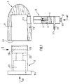
- FIG. 1 to 3 show in a highly schematic representation a spotlight head, by the way, not illustrated lamp with a wooden carved Spotlight housing 1, which is essentially axially symmetrical is constructed and in the front part a cylindrical, has a parabolic shape in the rear.
- the cylindrical interior 1.1 of the spotlight housing 1 has a front insert opening 1.2 and in the lateral lateral surface a push-through opening 1.3.
- an insert part 2 in Arrow direction A1 can be used, the one essentially has cylindrical outer contour and inside an insert cavity 2.1 and a lamp support thread 2.2 has, while at the front end in inserted condition to the front of the spotlight housing 1 applied flange 2.4 is arranged.
- a recess 2.3 with an essentially U-shaped open to the rear Cross-section.
- the arrangement of this recess 2.3 is such that the inserted state of the Insert part 2 is aligned with push-through opening 1.3.
- a push-through part 3 can be used in such a way that it is in the inserted state the insert part 2 through the recess 2.3 is passed through.
- the push-through part 3 serve in the recess 2.3 of the insert part 2 Guide grooves 2.5 of the insert part 2, the corresponding Guide ribs 3.5 on the side walls of the push-through part 3 cooperate.
- other guidance means can also be provided here his.
- a contact carrier 4 is arranged in the push-through part 3, the one central contact 5 and one side contact 6 carries, to which in not specifically shown Way leads 5.1 or 6.1 are connected, which led out of the push-through part 3 on the underside are.
- At the push-through part 3 closes a joint in a manner not shown below over which the lamp head with a support tube or the like is connected and in one piece and materially connected to the push-through part 3 can be.
- the push-through part 3 has a flange 3.1 which when plugged in to the outside of the Spotlight housing 1 creates.
- the flange 3.1 is with provided a through hole 7.1, through which he by means of a screw, not shown, on the spotlight housing 1 can be attached to this Purpose carries a screw hole 7.2.
- the spotlight head shown is installed in such a way that the supply lines 5.1 or 6.1 are connected to the contact carrier 4. Subsequently the contact carrier 4 in the push-through part 3 used.
- FIG. 4 to 7 also show in a highly schematic Representing a spotlight head in a bit another embodiment with a also made of wood worked spotlight housing 11, which is analogous to that Spotlight housing 1 is constructed.
- the cylindrical interior 11.1 of the lamp housing 11 has one front insert opening 11.2 and in the side Shell surface a push-through opening 11.3.
- Insert part 12 can be used in the direction of arrow A1 ' again an interior cavity 12.1 and has a lamp support thread 12.2, while on front end in the inserted state to the Front of the spotlight housing 11 applied Flange 12.4 is arranged.
- This flange 12.4 can, as shown in Fig. 4, part of a Be carrier ring, which is arranged on the insert part 12 External thread 12.7 connected to this is.
- the flange 12.4 ' can also, as in Fig. 5th shown in a variant of this embodiment, integrally connected to the insert part 12 his.
- a push-through part 13 can be used in the inserted state of the insert 12 passed through the insertion opening 12.3 becomes.
- the contact carrier 14 is, as shown in FIGS. 6 and 7 take in a direction A3 ', which is perpendicular to the longitudinal axis and direction of insertion of the push-through part 13 runs, attachable to this such that the cylindrical outer surface 14.1 of the contact carrier 14 in a corresponding cylindrical inner surface 13.2 of the push-through part 13 engages.
- the contact carrier 14 contains a central contact 15 and one Side contact 16, the 14.3 via crimp connections Supply lines 15.1 and 16.1 are connected, which through the push-through part 13 and the joint 18 are led outside.
- the push-through part 13 has a flange 13.1 which when plugged in to the outside of the Spotlight housing 11 creates.
- the flange 13.1 is with provided a through hole 17.1, through which he attached to the spotlight housing 11 by means of a screw can be used for this purpose a screw hole 17.2.
- the spotlight head shown is installed analogously to the example according to FIGS. 1 to 3 in such a way that the leads 15.1 and 16.1 on the contact carrier 14 are connected and the contact carrier 14 to the Push-through part 13 is attached. Then the insert part 12 in the direction of arrow A1 'in the spotlight housing 11 inserted. It is aligned in the end position with the insertion opening 12.3 in the insert part 12 the push-through opening 11.3 in the spotlight housing 11. Then become push-through part 13 and contact carrier 14 in the direction of arrow A2 'in the push-through opening 11.3 the spotlight housing 11 and the insertion opening 12.3 of the insert 12 inserted.
- contact carriers and lamp holder designed such that a Lamp with screw thread, for example with a Lamp base E14 can be used.
- a Lamp with screw thread for example with a Lamp base E14
- contact carrier and Train lamp holder so that, for example, a Halogen low-voltage reflector lamp with lamp pins or a halogen high-voltage lamp with loop contacts can be used.
- the contact carrier in a manner not shown, two plug contacts and the lamp holder a double spring (Flat spring) or it is a double spring educated. This allows lamps with base types GU 5.3 or G 9 in the lamp support device be used.
Landscapes
- Engineering & Computer Science (AREA)
- General Engineering & Computer Science (AREA)
- Fastening Of Light Sources Or Lamp Holders (AREA)
- Non-Portable Lighting Devices Or Systems Thereof (AREA)
- Arrangement Of Elements, Cooling, Sealing, Or The Like Of Lighting Devices (AREA)
Abstract
Description
Der Erfindung betrifft eine Lampenträgereinrichtung an einer Gelenkleuchte mit einem Strahlerkopf.The invention relates to a lamp support device on an articulated lamp with a spotlight head.
Der Erfindung liegt die Aufgabe zugrunde, eine Lampenträgereinrichtung zu schaffen für eine Leuchte, die ein sehr klein gehaltenes Strahlergehäuse besitzt, das aus unterschiedlichen Materialien, insbesondere aber aus Holz bestehen kann, wobei die Lampenträgereinrichtung so beschaffen sein sollte, daß trotz der Kleinheit des Strahlergehäuses und der Enge des zur Verfügung stehenden Raumes eine rasche und einfache Montage der Lampenträgereinrichtung möglich ist. The invention has for its object a lamp support device to create for a lamp, which has a very small spotlight housing, that from different materials, in particular but can be made of wood, the lamp support device should be such that despite the smallness of the spotlight housing and the tightness of the available space a quick and simple mounting of the lamp support device possible is.
Die Lösung dieser Aufgabe geschieht mit den Merkmalen aus dem Patentanspruch 1. Vorteilhafte Weiterbildungen der Erfindung sind in den abhängigen Ansprüchen beschrieben.This problem is solved with the features from claim 1. Advantageous further developments of the invention are in the dependent claims described.
Übliche Strahlerleuchten weisen Lampenträgereinrichtungen auf, welche eine Fassung mit einem Lampenträger zur mechanischen Befestigung der Lampe und einen Kontaktträger zur elektrischen Kontaktierung der Lampe besitzen.Usual spotlights have lamp holder devices on which a socket with a lamp holder for mechanical fastening of the lamp and one Contact carrier for electrical contacting of the lamp have.
Der Lampenträger kann beispielsweise als ein Glühlampentraggewinde (bei einer Edisonfassung E 27) oder als eine Haltefeder (bei einer Halogenfassung GU 5,3 für Niedervoltlampen mit Kaltlichtspiegel) ausgebildet sein. Derartige Fassungen werden im allgemeinen von der Vorderseite her in ein Strahlergehäuse eingesetzt.The lamp support can be used, for example, as a light bulb support thread (with an Edison version E 27) or as a retaining spring (with a halogen socket GU 5.3 for low-voltage lamps with cold light mirrors) his. Such versions are generally inserted into a spotlight housing from the front.
Außerdem sind derartige Strahlerleuchten im allgemeinen auf einem Gelenk befestigt, um den Lichtkegel ausrichten zu können. Das Gelenk ist mit einem Durchsteckteil versehen, welches in einer Durchstecköffnung am Strahlergehäuse befestigt ist. Die Durchstecköffnung ist häufig seitlich am Strahlergehäuse angebracht. Um der Strahlerleuchte ein gefälliges Aussehen zu geben, wird die Zuleitung verdeckt durch das Innere des Gelenks geführt. Um die Fassungskontakte an die Zuleitung anzuschließen, muß diese deshalb durch das Strahlergehäuse durchgeführt und außerhalb des Gehäuses kontaktiert werden. Anschließend muß die Fassung in das Strahlergehäuse eingesetzt werden, wobei der Überstand der Zuleitung im Inneren des Strahlergehäuses untergebracht oder durch das Gelenk zurückgezogen werden muß.In addition, such spotlights are generally fixed on a hinge to the light cone to be able to align. The joint is with a push-through part provided, which in a push-through opening is attached to the spotlight housing. The push-through opening is often on the side of the spotlight housing appropriate. A pleasant compliment to the spotlight To give the appearance, the supply line is covered by guided the inside of the joint. About the socket contacts Therefore, it must be connected to the supply line carried out by the spotlight housing and outside of the housing can be contacted. Subsequently the socket must be inserted in the spotlight housing be, the supernatant of the lead in Housed inside or through the spotlight housing the joint must be withdrawn.
Ein Grundgedanke der Erfindung besteht darin, die Bestandteile einer Fassung auf zwei unterschiedliche Bauteile der Strahlerleuchte zu verteilen, nämlich
- das Einsatzteil mit dem Lampenträger und
- das Durchsteckteil mit dem Kontaktträger.
- the insert with the lamp holder and
- the push-through part with the contact carrier.
Da diese Bauteile von verschiedenen Seiten, nämlich das Einsatzteil von vorne und das Durchsteckteil von der Seite her in das Strahlergehäuse eingesteckt werden, werden sich auch die die Fassung bildenden Bauteile erst im endgültig eingesetzten Zustand in der gebrauchsfertigen Lage zueinander befinden. Diese Ausbildung hat unter anderem den Vorteil, daß keine Zuleitungen durch das eng gebaute Strahlergehäuse hindurchgezogen bzw. in diesem untergebracht zu werden brauchen. Die Zuleitungen setzen vielmehr erst an den im Durchsteckteil angeordneten Kontakten an und werden nur aus diesem herausgeführt.Because these components come from different sides, namely the insert part from the front and the push-through part from be inserted into the spotlight housing from the side, will also be the components forming the frame only in the finally used state in the ready-to-use position to each other. This One of the advantages of training is that none Supply lines through the narrowly built spotlight housing to be pulled through or housed in this need. Rather, the feed lines are just beginning the contacts arranged in the push-through part on and are only brought out of this.
Dadurch kann der elektrische Anschluß der Fassungskontakte an die Zuleitung außerhalb des Strahlergehäuses erfolgen, da der Kontaktträger lediglich zuletzt gemeinsam mit der Zuleitung und dem Durchsteckteil durch die Durchstecköffnung eingeführt und fixiert wird. This allows the electrical connection of the socket contacts to the supply line outside the spotlight housing take place because the contact carrier only last together with the supply line and the push-through part inserted through the push-through opening and is fixed.
Schließlich kann das Durchsteckteil mit fertig angeschlossenen Zuleitungen und Gelenk als Baueinheit/Modul vorgefertigt werden, so daß zum Zusammenbau des Strahlerkopfes das Durchsteckteil lediglich in das Strahlergehäuse eingeführt und mit dem Einsatzteil mechanisch verrastet werden muß. Diese Baueinheit/Modul kann beispielsweise als Zulieferteil angeliefert werden, so daß die Endmontage des Strahlerkopfes sehr vereinfacht wird.Finally, the push-through part can be connected with it Supply lines and joint as a structural unit / module are prefabricated so that for assembly the push-through part of the spotlight head only inserted into the spotlight housing and with the insert must be mechanically locked. This assembly / module can, for example, as a supplier part be delivered so that the final assembly of the spotlight head is very simplified.
Im folgenden wird anhand der beigefügten Zeichnungen ein Ausführungsbeispiel für eine Lampenträgereinrichtung nach der Erfindung näher erläutert.The following is based on the accompanying drawings an embodiment of a lamp support device explained in more detail according to the invention.
In den Zeichnungen zeigen:
Die Fig. 1 bis 3 zeigen in stark schematisierter Darstellung einen Strahlerkopf einer im Übrigen nicht dargestellten Leuchte mit einem aus Holz gearbeiteten Strahlergehäuse 1, das im wesentlichen axialsymmetrisch aufgebaut ist und im vorderen Teil eine zylindrische, im hinteren eine parabolische Form aufweist. Der zylindrische Innenraum 1.1 des Strahlergehäuses 1 besitzt eine vordere Einsatzöffnung 1.2 und in der seitlichen Mantelfläche eine Durchstecköffnung 1.3. In den Innenraum 1.1 des Strahlergehäuses 1 ist durch die vordere Einsatzöffnung 1.2 ein Einsatzteil 2 in Pfeilrichtung A1 einsetzbar, das eine im wesentlichen zylindrische Außenkontur besitzt und in seinem Inneren eine Einsatzhöhlung 2.1 und ein Lampentraggewinde 2.2 aufweist, während am vorderen Ende ein sich im eingesetzten Zustand an die Vorderseite des Strahlergehäuses 1 anlegender Flansch 2.4 angeordnet ist. An dem hinteren Ende des Einsatzteils 2 befindet sich, wie aus Fig. 2 gut zu erkennen, eine Ausnehmung 2.3 mit einem nach hinten offenen, im wesentlichen U-förmigen Querschnitt. Die Anordnung dieser Ausnehmung 2.3 ist derart, daß die im eingesteckten zustand des Einsatzteils 2 zur Durchstecköffnung 1.3 fluchtet.1 to 3 show in a highly schematic representation a spotlight head, by the way, not illustrated lamp with a wooden carved Spotlight housing 1, which is essentially axially symmetrical is constructed and in the front part a cylindrical, has a parabolic shape in the rear. The cylindrical interior 1.1 of the spotlight housing 1 has a front insert opening 1.2 and in the lateral lateral surface a push-through opening 1.3. In the interior 1.1 of the lamp housing 1 is through the front insert opening 1.2 an insert part 2 in Arrow direction A1 can be used, the one essentially has cylindrical outer contour and inside an insert cavity 2.1 and a lamp support thread 2.2 has, while at the front end in inserted condition to the front of the spotlight housing 1 applied flange 2.4 is arranged. On is the rear end of the insert 2, as can be seen clearly from FIG. 2, a recess 2.3 with an essentially U-shaped open to the rear Cross-section. The arrangement of this recess 2.3 is such that the inserted state of the Insert part 2 is aligned with push-through opening 1.3.
Durch die Durchstecköffnung 1.3 ist in den Innenraum
1.1 des Strahlergehäuses 1 ein Durchsteckteil 3 einsetzbar
und zwar derart, daß es im eingesetzten Zustand
des Einsatzteils 2 durch die Ausnehmung 2.3
hindurchgeführt wird. Zur Führung des Durchsteckteils
3 in der Ausnehmung 2.3 des Einsatzteils 2 dienen
Führungsnuten 2.5 des Einsatzteils 2, die mit entsprechenden
Führungsrippen 3.5 an den Seitenwänden
des Durchsteckteils 3 zusammenwirken. Selbstverständlich
können hier auch andere Führungsmittel vorgesehen
sein.Through the through opening 1.3 is in the interior
1.1 of the radiator housing 1, a push-through
Im Durchsteckteil 3 ist ein Kontaktträger 4 angeordnet,
der einen Zentralkontakt 5 und einen Seitenkontakt
6 trägt, an welche in nicht eigens dargestellter
Weise Zuleitungen 5.1 bzw. 6.1 angeschlossen sind,
die aus dem Durchsteckteil 3 an der Unterseite herausgeführt
sind. An das Durchsteckteil 3 schließt
sich in nicht dargestellter Weise unten ein Gelenk
an, über welches der Leuchtenkopf mit einem Tragrohr
oder dergleichen verbunden ist und das einstückig und
materialeinheitlich mit dem Durchsteckteil 3 verbunden
sein kann. A contact carrier 4 is arranged in the push-through
Das Durchsteckteil 3 besitzt einen Flansch 3.1, der
sich im eingesteckten Zustand an die Außenseite des
Strahlergehäuses 1 anlegt. Der Flansch 3.1 ist mit
einem Durchgangsloch 7.1 versehen, über welches er
mittels einer nicht dargestellten Schraube am Strahlergehäuse
1 befestigt werden kann, das zu diesem
Zweck ein Schraubenloch 7.2 trägt.The push-through
Die Montage des dargestellten Strahlerkopfes erfolgt
in der Weise, daß zunächst die Zuleitungen 5.1 bzw.
6.1 am Kontaktträger 4 angeschlossen werden. Anschließend
wird der Kontaktträger 4 in das Durchsteckteil
3 eingesetzt.The spotlight head shown is installed
in such a way that the supply lines 5.1 or
6.1 are connected to the contact carrier 4. Subsequently
the contact carrier 4 in the push-through
Danach wird das Einsatzteil 2 in Pfeilrichtung A1 in
das Strahlergehäuse 1 eingesteckt. Dabei muß die Ausnehmung
2.3 im Einsatzteil 2 mit der Durchstecköffnung
1.3 im Strahlergehäuse 1 fluchten. Anschließend
wird das Durchsteckteil 3 in Pfeilrichtung A2 in die
Durchstecköffnung 1.3 des Strahlergehäuses 1 sowie
die Ausnehmung 2.3 des Einsatzteils 2 durchgesteckt.
Im eingesetzten Zustand liegen dann der Zentralkontakt
5 und der Seitenkontakt 6 an den vorgesehenen
stellen hinter dem Lampentraggewinde 2.2.Then the insert 2 in the direction of arrow A1 in
the spotlight housing 1 is inserted. The recess
2.3 in insert part 2 with the push-through opening
1.3 align in the spotlight housing 1. Subsequently
the push-through
Die Fig. 4 bis 7 zeigen ebenfalls in stark schematisierter
Darstellung einen Strahlerkopf in einer etwas
anderen Ausführungsform mit einem ebenfalls aus Holz
gearbeiteten Strahlergehäuse 11, das analog dem
Strahlergehäuse 1 aufgebaut ist. Der zylindrische Innenraum
11.1 des Strahlergehäuses 11 besitzt eine
vordere Einsatzöffnung 11.2 und in der seitlichen
Mantelfläche eine Durchstecköffnung 11.3. In den Innenraum
11.1 ist durch die Einsatzöffnung 11.2 ein
Einsatzteil 12 in Pfeilrichtung A1' einsetzbar, das
wiederum in seinem Inneren eine Einsatzhöhlung 12.1
und ein Lampentraggewinde 12.2 aufweist, während am
vorderen Ende ein sich im eingesetzten Zustand an die
Vorderseite des Strahlergehäuses 11 anlegender
Flansch 12.4 angeordnet ist. Dieser Flansch 12.4
kann, wie in Fig. 4 dargestellt, Bestandteil eines
Trägerrings sein, der über ein am Einsatzteil 12 angeordnetes
Außengewinde 12.7 mit diesem verbunden
ist. Der Flansch 12.4' kann aber auch, wie in Fig. 5
bei einer Variante dieses Ausführungsbeispiels dargestellt,
einstückig mit dem Einsatzteil 12 verbunden
sein.4 to 7 also show in a highly schematic
Representing a spotlight head in a bit
another embodiment with a also made of wood
worked
Am hinteren Ende des Einsatzteils 12 befindet sich,
wie aus den Fig. 4 und 5 zu erkennen, bei diesem Ausführungsbeispiel
eine Einstecköffnung 12.3, die im
eingesetzten Zustand des Einsatzteils 12 mit der
Durchstecköffnung 11.3 fluchtet.At the rear end of the
Durch die Durchstecköffnung 11.3 ist in dem Innenraum
11.1 des Strahlergehäuses 11 ein Durchsteckteil 13
einsetzbar, das im eingesetzten Zustand des Einsatzteils
12 durch die Einstecköffnung 12.3 hindurchgeführt
wird. Zur Führung des Durchsteckteils 13 in der
Einstecköffnung 12.3 des Einsatzteils 12 dienen Führungselemente,
z.B. Führungsrippen 12.5 im Einsatzteil
12, die mit entsprechenden Führungselementen
13.5 bzw. 14.5 zusammenwirken, die am Durchsteckteil
13 bzw. dem an das Durchsteckteil 13 angesetzten Kontaktträger
14 angeordnet sind und gemeinsam eine Führungsnut
begrenzen.Through the push-through opening 11.3 is in the interior
11.1 of the
Der Kontaktträger 14 ist, wie aus den Fig. 6 und 7 zu
entnehmen, in einer Richtung A3', welche senkrecht
zur Längsachse und Einsetzrichtung des Durchsteckteils
13 verläuft, an dieses ansetzbar derart, daß
die zylindrische Außenfläche 14.1 des Kontaktträgers
14 in eine entsprechende zylindrische Innenfläche
13.2 des Durchsteckteils 13 eingreift. Der Kontaktträger
14 enthält einen Zentralkontakt 15 und einen
Seitenkontakt 16, die über Crimpanschlüsse 14.3 an
Zuleitungen 15.1 bzw. 16.1 angeschlossen sind, welche
durch das Durchsteckteil 13 und das Gelenk 18 hindurch
nach außen geführt sind.The
Das Durchsteckteil 13 besitzt einen Flansch 13.1, der
sich im eingesteckten Zustand an die Außenseite des
Strahlergehäuses 11 anlegt. Der Flansch 13.1 ist mit
einem Durchgangsloch 17.1 versehen, über welches er
mittels einer Schraube am Strahlergehäuse 11 befestigt
werden kann, das zu diesem Zweck ein Schraubenloch
17.2 aufweist.The push-through
Die Montage des dargestellten Strahlerkopfes erfolgt
analog zum Beispiel gemäß Fig. 1 bis 3 in der Weise,
daß die Zuleitungen 15.1 und 16.1 am Kontaktträger 14
angeschlossen werden und der Kontaktträger 14 an das
Durchsteckteil 13 angesetzt wird. Dann wird das Einsatzteil
12 in Pfeilrichtung A1' in das Strahlergehäuse
11 eingesteckt. Dabei fluchtet in der Endstellung
die Einstecköffnung 12.3 im Einsatzteil 12 mit
der Durchstecköffnung 11.3 im Strahlergehäuse 11. Anschließend
werden Durchsteckteil 13 und Kontaktträger
14 in Pfeilrichtung A2' in die Durchstecköffnung 11.3
des Strahlergehäuses 11 sowie die Einstecköffnung
12.3 des Einsatzteils 12 durchgesteckt. Dabei rastet
im eingesteckten Zustand des Durchsteckteils 13 eine
Rastnase 13.3 hinter eine Rastfläche 12.6 im Einsatzteil
12 ein und das Durchsteckteil 13 liegt mit einer
Anschlagfläche 13.7 an einer Gegenfläche 12.8 des
Einsatzteils 12 an, so daß dann das Durchsteckteil 13
mit dem Kontaktträger 14 zusammen mit dem Einsatzteil
12 im Strahlergehäuse 11 fixiert sind. Im montierten
Zustand liegen dann der Zentralkontakt 15 und der
Seitenkontakt 16 an den vorgesehenen Stellen hinter
dem Lampentraggewinde 12.2.The spotlight head shown is installed
analogously to the example according to FIGS. 1 to 3 in such a way
that the leads 15.1 and 16.1 on the
Im dargestellten Ausführungsbeispiel sind Kontaktträger und Lampenträger derart ausgebildet, daß eine Lampe mit Schraubgewinde, beispielsweise mit einem Lampensockel E14 eingesetzt werden kann. Selbstverständlich ist es bei der dargestellten Lampenträgereinrichtung auch möglich, Kontaktträger und Lampenträger so auszubilden, daß beispielsweise eine Halogen-Niedervolt-Reflektorlampe mit Lampenstiften oder eine Halogen-Hochvolt-Lampe mit Schlaufenkontakten eingesetzt werden kann. Zu diesem Zweck weist dann der Kontaktträger, in nicht dargestellter Weise, zwei Steckkontakte auf und der Lampenträger eine Doppelfeder (Flachfeder) oder er ist als Doppelfeder ausgebildet. Auf diese Weise können Lampen mit Sockeltypen GU 5,3 bzw. G 9 in die Lampenträgereinrichtung eingesetzt werden.In the illustrated embodiment, contact carriers and lamp holder designed such that a Lamp with screw thread, for example with a Lamp base E14 can be used. Of course it is in the lamp support device shown also possible contact carrier and Train lamp holder so that, for example, a Halogen low-voltage reflector lamp with lamp pins or a halogen high-voltage lamp with loop contacts can be used. For this purpose points then the contact carrier, in a manner not shown, two plug contacts and the lamp holder a double spring (Flat spring) or it is a double spring educated. This allows lamps with base types GU 5.3 or G 9 in the lamp support device be used.
Claims (24)
Applications Claiming Priority (2)
| Application Number | Priority Date | Filing Date | Title |
|---|---|---|---|
| DE19822974 | 1998-05-25 | ||
| DE1998122974 DE19822974A1 (en) | 1998-05-25 | 1998-05-25 | Lamp support device on an articulated lamp with a spotlight head |
Publications (2)
| Publication Number | Publication Date |
|---|---|
| EP0961077A2 true EP0961077A2 (en) | 1999-12-01 |
| EP0961077A3 EP0961077A3 (en) | 2000-03-08 |
Family
ID=7868636
Family Applications (1)
| Application Number | Title | Priority Date | Filing Date |
|---|---|---|---|
| EP99110037A Withdrawn EP0961077A3 (en) | 1998-05-25 | 1999-05-21 | Lamp holder device for an articulated lamp assembly comprising a light head |
Country Status (2)
| Country | Link |
|---|---|
| EP (1) | EP0961077A3 (en) |
| DE (1) | DE19822974A1 (en) |
Cited By (2)
| Publication number | Priority date | Publication date | Assignee | Title |
|---|---|---|---|---|
| DE10049642C2 (en) * | 2000-10-05 | 2002-12-05 | Vlm W Murjahn Gmbh & Co Kg | Lamp holder device for halogen high-voltage lamps with a two-pin base, in particular base GU10 or GZ10, on a spotlight |
| DE202018105238U1 (en) * | 2018-09-13 | 2019-12-16 | Zumtobel Lighting Gmbh | lamp |
Family Cites Families (3)
| Publication number | Priority date | Publication date | Assignee | Title |
|---|---|---|---|---|
| DE9305897U1 (en) * | 1993-04-20 | 1993-06-17 | Brökelmann, Jaeger & Busse GmbH & Co, 5760 Arnsberg | Lamp holder |
| DE4402089C2 (en) * | 1994-01-25 | 1995-11-16 | Broekelmann Jaeger & Busse | Incandescent lamp holder |
| DE4432302C2 (en) * | 1994-09-10 | 1997-01-16 | Murjahn Kg Vlm | Lamp fastening device that can be inserted into a luminaire housing |
-
1998
- 1998-05-25 DE DE1998122974 patent/DE19822974A1/en not_active Ceased
-
1999
- 1999-05-21 EP EP99110037A patent/EP0961077A3/en not_active Withdrawn
Non-Patent Citations (1)
| Title |
|---|
| None |
Cited By (2)
| Publication number | Priority date | Publication date | Assignee | Title |
|---|---|---|---|---|
| DE10049642C2 (en) * | 2000-10-05 | 2002-12-05 | Vlm W Murjahn Gmbh & Co Kg | Lamp holder device for halogen high-voltage lamps with a two-pin base, in particular base GU10 or GZ10, on a spotlight |
| DE202018105238U1 (en) * | 2018-09-13 | 2019-12-16 | Zumtobel Lighting Gmbh | lamp |
Also Published As
| Publication number | Publication date |
|---|---|
| EP0961077A3 (en) | 2000-03-08 |
| DE19822974A1 (en) | 1999-12-02 |
Similar Documents
| Publication | Publication Date | Title |
|---|---|---|
| EP2367235B1 (en) | Plug for connecting with a socket | |
| EP1264138B1 (en) | Built-in illuminator comprising a supporting ring for additional components | |
| EP1264136B1 (en) | Built-in lamp with a dome-shaped reflector | |
| DE9214524U1 (en) | Plastic electric lamp holder | |
| EP0961077A2 (en) | Lamp holder device for an articulated lamp assembly comprising a light head | |
| DE4121575C1 (en) | ||
| DE202006009812U1 (en) | Explosion protection fitting for lamps illuminating e.g. oil platforms or gas tanks, from which cover is not readily removed, includes lengthy protection assembly completed by cover and covering sections | |
| DE8424990U1 (en) | proximity switch | |
| EP0664584A1 (en) | Socket for incandescent lamp | |
| DE586006C (en) | Electric hand lamp | |
| DE3908618C2 (en) | ||
| EP3282178A1 (en) | Connector for a lamp body | |
| DE19624591C2 (en) | Lamp holder for fastening in a luminaire housing | |
| EP0477636B1 (en) | Electrical adapter | |
| DE3338628A1 (en) | RECESSED HEADLIGHT | |
| EP0098504A2 (en) | Explosion-proof light fitting | |
| DE10049642C2 (en) | Lamp holder device for halogen high-voltage lamps with a two-pin base, in particular base GU10 or GZ10, on a spotlight | |
| AT407783B (en) | Fastening and connecting system for quick mounting of lamps, in particular lamps having a watertight housing | |
| EP1037324A1 (en) | Connector for a coaxial cable | |
| DE7705941U1 (en) | In particular, water-protected socket for fluorescent lamps | |
| DE69837191T2 (en) | lamp | |
| DE3601993A1 (en) | Adaptor for electrical incandescent lamps | |
| DE19609547A1 (en) | Pivot-mounted lamp with tubular housing section | |
| DE29607524U1 (en) | Electric flashlight with warning stick function | |
| DE8017078U1 (en) | LAMP FOR FLUORESCENT TUBE LAMPS WITH DOUBLE-PIN BASES |
Legal Events
| Date | Code | Title | Description |
|---|---|---|---|
| PUAI | Public reference made under article 153(3) epc to a published international application that has entered the european phase |
Free format text: ORIGINAL CODE: 0009012 |
|
| AK | Designated contracting states |
Kind code of ref document: A2 Designated state(s): BE DE DK FR IT NL |
|
| AX | Request for extension of the european patent |
Free format text: AL;LT;LV;MK;RO;SI |
|
| PUAL | Search report despatched |
Free format text: ORIGINAL CODE: 0009013 |
|
| AK | Designated contracting states |
Kind code of ref document: A3 Designated state(s): AT BE CH CY DE DK ES FI FR GB GR IE IT LI LU MC NL PT SE |
|
| AX | Request for extension of the european patent |
Free format text: AL;LT;LV;MK;RO;SI |
|
| 17P | Request for examination filed |
Effective date: 20000905 |
|
| AKX | Designation fees paid |
Free format text: BE DE DK FR IT NL |
|
| 17Q | First examination report despatched |
Effective date: 20020607 |
|
| STAA | Information on the status of an ep patent application or granted ep patent |
Free format text: STATUS: THE APPLICATION IS DEEMED TO BE WITHDRAWN |
|
| 18D | Application deemed to be withdrawn |
Effective date: 20021018 |