EP0210323B1 - Fehlerfeststellungssystem für einen Motor mit Sensoren - Google Patents
Fehlerfeststellungssystem für einen Motor mit Sensoren Download PDFInfo
- Publication number
- EP0210323B1 EP0210323B1 EP86101290A EP86101290A EP0210323B1 EP 0210323 B1 EP0210323 B1 EP 0210323B1 EP 86101290 A EP86101290 A EP 86101290A EP 86101290 A EP86101290 A EP 86101290A EP 0210323 B1 EP0210323 B1 EP 0210323B1
- Authority
- EP
- European Patent Office
- Prior art keywords
- sensor
- failure
- engine
- output signal
- judgement
- Prior art date
- Legal status (The legal status is an assumption and is not a legal conclusion. Google has not performed a legal analysis and makes no representation as to the accuracy of the status listed.)
- Expired
Links
Images


Classifications
-
- F—MECHANICAL ENGINEERING; LIGHTING; HEATING; WEAPONS; BLASTING
- F02—COMBUSTION ENGINES; HOT-GAS OR COMBUSTION-PRODUCT ENGINE PLANTS
- F02D—CONTROLLING COMBUSTION ENGINES
- F02D41/00—Electrical control of supply of combustible mixture or its constituents
- F02D41/22—Safety or indicating devices for abnormal conditions
- F02D41/222—Safety or indicating devices for abnormal conditions relating to the failure of sensors or parameter detection devices
-
- F—MECHANICAL ENGINEERING; LIGHTING; HEATING; WEAPONS; BLASTING
- F02—COMBUSTION ENGINES; HOT-GAS OR COMBUSTION-PRODUCT ENGINE PLANTS
- F02D—CONTROLLING COMBUSTION ENGINES
- F02D41/00—Electrical control of supply of combustible mixture or its constituents
- F02D41/22—Safety or indicating devices for abnormal conditions
- F02D2041/227—Limping Home, i.e. taking specific engine control measures at abnormal conditions
-
- Y—GENERAL TAGGING OF NEW TECHNOLOGICAL DEVELOPMENTS; GENERAL TAGGING OF CROSS-SECTIONAL TECHNOLOGIES SPANNING OVER SEVERAL SECTIONS OF THE IPC; TECHNICAL SUBJECTS COVERED BY FORMER USPC CROSS-REFERENCE ART COLLECTIONS [XRACs] AND DIGESTS
- Y02—TECHNOLOGIES OR APPLICATIONS FOR MITIGATION OR ADAPTATION AGAINST CLIMATE CHANGE
- Y02T—CLIMATE CHANGE MITIGATION TECHNOLOGIES RELATED TO TRANSPORTATION
- Y02T10/00—Road transport of goods or passengers
- Y02T10/10—Internal combustion engine [ICE] based vehicles
- Y02T10/40—Engine management systems
Definitions
- This invention relates to failure judgement or sensor apparatus for an engine.
- the internal combustion engine for automobiles is controlled by a microcomputer
- various data concerned with the engine is usually detected and controlled by a number of sensors.
- the failure judgement system of the sensor which detects various data for accurate control, which detects various data for accurate control, performs an important role for controlling engines and a plurality of means are adopted for the failure judgement.
- Fail safe function is a function to perform the stop of the engine or to perform the change-over control by adopting alternative standard value for emergency evacuation previously presumed for fear of the emergency such as bad condition for the engine and abnormal overheating of the catalyst. probably occurred when the control is continued reliably in response to the signal outputted abnormally by dint of the number of the sensor.
- US-A-4 274 381 discloses a failure judgement means as presented by the circuitry 26 is provided, said failure judgement means, apart from the output of the engine coolant temperature sensor that is to be supervised, receiving the output signal of an additional engine temperature sensor and outputting a control signal for controlling the fuel injection of an internal combustion engine by means of an AND-connection only if output signals of these two temperature sensors indicating equivalent temperature values are obtained. If no equivalent output signal of the engine coolant temperature sensor is present, this output signal is suppressed and replaced by a standard value (Vo) corresponding to a usual medium coolant temperature of 80°.
- Vo standard value
- Another object of this invention is to provide the failure judgement system which enables to make the system free from the dangerous condition.
- Further object of this invention is to provide the failure judgement system which can prevent to misjudge the sensor to be abnormal even if the sensor is normal.
- Numeral 16 denotes an igniter which generates the high-power voltage required to the spark plug 3.
- Numeral 17 denotes a distributor interlocking with a crankshaft which is not illustrated here.
- Numeral 18 denotes a crank angle sensor installed in the distributor 17. The sensor provides four pulse signals per one revolution of the distributor 17 or twice of the crankshaft.
- Numeral 20 shows the electronic control unit as the electronic controlled part.
- Numeral 21 denotes a key switch.
- Numeral 22 denotes a battery which supplies electric power to the power source 23 within the electronic controlled unit 20 via the key switch 21.
- the voltage of water temperature sensor 9 (VTHW) is judged whether or not it is within the range from 0.5 V to 4.5 V in decision point 300. If the result is corresponding to the above-mentioned range, the calculation to get the temperature of cooling water (THW) by means of the value of VTHW is carried out in step 301, and once the process exits. If the value of VTHW is not corresponding to the above-mentioned range, the THW sensor is judged as failure in step 302, the standard value 80°C is substituted for THw in step 303, and once the process exits.
- the THW is calculated when the value of VTHW is within the range from 0.5 V to 4.5 V in point 300. If not, the THW sensor is judged as failure and the THW is replaced by the standard value.
- Figure 5 illustrates and described the second embodiment. While the second embodiment is similar to the first embodiment in Figure 2, there are some differences in the judgement system of the intake pressure Pim and the cooling water temperature THW in Point 100 and 103. The differences are found in only points 400 and 403 as follows:
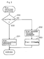
- FIG. 7 is a flowchart illustrative of the PimF process subroutine, where the intake pressure Pim which is used in the flowchart of Figure 6 is detected and the pressure sensor failure flag PimF is also set or reset. The followings are the explanation of Pim process subroutine.
Landscapes
- Engineering & Computer Science (AREA)
- Chemical & Material Sciences (AREA)
- Combustion & Propulsion (AREA)
- Mechanical Engineering (AREA)
- General Engineering & Computer Science (AREA)
- Combined Controls Of Internal Combustion Engines (AREA)
- Electrical Control Of Air Or Fuel Supplied To Internal-Combustion Engine (AREA)
- Testing Or Calibration Of Command Recording Devices (AREA)
Claims (5)
Applications Claiming Priority (2)
| Application Number | Priority Date | Filing Date | Title |
|---|---|---|---|
| JP163226/85 | 1985-07-23 | ||
| JP60163226A JPH0711435B2 (ja) | 1985-07-23 | 1985-07-23 | 内燃機関のセンサ異常判定方法 |
Publications (3)
| Publication Number | Publication Date |
|---|---|
| EP0210323A2 EP0210323A2 (de) | 1987-02-04 |
| EP0210323A3 EP0210323A3 (en) | 1987-10-14 |
| EP0210323B1 true EP0210323B1 (de) | 1989-10-11 |
Family
ID=15769714
Family Applications (1)
| Application Number | Title | Priority Date | Filing Date |
|---|---|---|---|
| EP86101290A Expired EP0210323B1 (de) | 1985-07-23 | 1986-01-31 | Fehlerfeststellungssystem für einen Motor mit Sensoren |
Country Status (4)
| Country | Link |
|---|---|
| US (1) | US4780826A (de) |
| EP (1) | EP0210323B1 (de) |
| JP (1) | JPH0711435B2 (de) |
| DE (1) | DE3666265D1 (de) |
Cited By (1)
| Publication number | Priority date | Publication date | Assignee | Title |
|---|---|---|---|---|
| DE4004086A1 (de) * | 1990-02-10 | 1991-08-14 | Bosch Gmbh Robert | System zur steuerung bzw. regelung einer brennkraftmaschine in einem kraftfahrzeug |
Families Citing this family (41)
| Publication number | Priority date | Publication date | Assignee | Title |
|---|---|---|---|---|
| US4736626A (en) * | 1986-04-16 | 1988-04-12 | Nippondenso Co., Ltd. | Abnormality detection apparatus for vehicle engines |
| JPS63131847A (ja) * | 1986-04-28 | 1988-06-03 | Mitsubishi Electric Corp | 車両用制御装置 |
| JPS63246449A (ja) * | 1987-03-31 | 1988-10-13 | Nippon Denso Co Ltd | 内燃機関制御装置 |
| JPH0717007Y2 (ja) * | 1987-05-28 | 1995-04-19 | 日産自動車株式会社 | 車速センサ−異常検出装置 |
| JP2583893B2 (ja) * | 1987-06-05 | 1997-02-19 | 富士重工業株式会社 | エンジンの空燃比学習制御装置 |
| JPH01208549A (ja) * | 1988-02-16 | 1989-08-22 | Fuji Heavy Ind Ltd | エンジンの吸気系故障検知装置 |
| JPH01217253A (ja) * | 1988-02-25 | 1989-08-30 | Nissan Motor Co Ltd | 酸素センサの故障診断装置 |
| US4951632A (en) * | 1988-04-25 | 1990-08-28 | Honda Giken Kogyo K.K. | Exhaust gas component concentration sensing device and method of detecting failure thereof |
| AU614178B2 (en) * | 1988-07-29 | 1991-08-22 | Mitsubishi Jidosha Kogyo Kabushiki Kaisha | Fail-safe device for a temperature sensor |
| JP2749138B2 (ja) * | 1988-08-08 | 1998-05-13 | 株式会社日立製作所 | 内燃機関の燃焼異常検出装置 |
| JP2516188B2 (ja) * | 1988-09-22 | 1996-07-10 | 本田技研工業株式会社 | 温度センサの異常処理装置 |
| DE3840148A1 (de) * | 1988-11-29 | 1990-05-31 | Bosch Gmbh Robert | Verfahren und vorrichtung zum erkennen eines fehlerzustandes einer lambdasonde |
| US4875456A (en) * | 1989-02-08 | 1989-10-24 | Japan Electronic Control Systems Company Limited | Self-diagnosis system for auxiliary air control system of internal combustion engine |
| JP2663631B2 (ja) * | 1989-05-23 | 1997-10-15 | 日産自動車株式会社 | 自動変速機の制御装置 |
| JPH0361125A (ja) * | 1989-07-12 | 1991-03-15 | Robert Bosch Gmbh | 自動車の運転方法 |
| US5017910A (en) * | 1989-08-24 | 1991-05-21 | Deere & Company | Intermittent fault detection system |
| JPH03233160A (ja) * | 1990-02-08 | 1991-10-17 | Mitsubishi Electric Corp | エンジンの制御装置 |
| US5235527A (en) * | 1990-02-09 | 1993-08-10 | Toyota Jidosha Kabushiki Kaisha | Method for diagnosing abnormality of sensor |
| JP2844815B2 (ja) * | 1990-03-16 | 1999-01-13 | 株式会社デンソー | 車両用電子制御装置 |
| JP2503742B2 (ja) * | 1990-08-04 | 1996-06-05 | 三菱電機株式会社 | 内燃機関燃料制御システム |
| US5109165A (en) * | 1990-12-11 | 1992-04-28 | Gaymar Industries, Inc. | Failsafe feedback control system |
| US5243324A (en) * | 1991-11-07 | 1993-09-07 | Ford Motor Company | Method of detecting a fault in an automotive system |
| JP2688674B2 (ja) * | 1992-01-20 | 1997-12-10 | 本田技研工業株式会社 | 燃料タンク内圧センサの故障検出装置及び故障補償装置 |
| JP2639287B2 (ja) * | 1992-08-11 | 1997-08-06 | 株式会社デンソー | 車両の自己診断装置 |
| DE4423344A1 (de) * | 1994-07-04 | 1996-01-11 | Bayerische Motoren Werke Ag | Verfahren zur Erkennung von seitenverkehrt angeschlossenen Lambda-Sonden |
| US5574645A (en) * | 1995-02-28 | 1996-11-12 | Snap-On Technologies, Inc. | Manifold absolute pressure sensor emulator |
| JPH08338299A (ja) * | 1995-06-10 | 1996-12-24 | Robert Bosch Gmbh | ミスファイア検出方法 |
| JP3675108B2 (ja) * | 1996-06-24 | 2005-07-27 | トヨタ自動車株式会社 | 水温センサの故障診断装置 |
| JP3189701B2 (ja) * | 1996-10-03 | 2001-07-16 | 日産自動車株式会社 | 車両用温度センサの異常判定装置 |
| DE19708243C1 (de) * | 1997-02-28 | 1998-08-13 | Siemens Ag | Verfahren und Einrichtung zum Steuern einer Brennkraftmaschine |
| JP3629982B2 (ja) | 1998-10-27 | 2005-03-16 | 日産自動車株式会社 | 冷却液温度センサの診断装置 |
| US6434476B1 (en) * | 2000-10-04 | 2002-08-13 | Detroit Diesel Corporation | High voltage fault discrimination for EGR temperature sensor |
| DE10153396A1 (de) * | 2001-11-01 | 2003-05-28 | Siemens Ag | Einrichtung zur Ansteuerung einer elektrischen Kraftstoffpumpe |
| DE102006021306B3 (de) * | 2006-05-08 | 2007-11-29 | Robert Bosch Gmbh | Verfahren zur Diagnose und Steuervorrichtung zur Steuerung eines Kraftfahrzeuges |
| DE102006048169A1 (de) * | 2006-10-10 | 2008-04-17 | Robert Bosch Gmbh | Verfahren zur Überwachung einer Funktionsfähigkeit einer Steuerung |
| JP5218526B2 (ja) * | 2010-11-11 | 2013-06-26 | トヨタ自動車株式会社 | 水温センサ異常判定装置 |
| JP6082242B2 (ja) * | 2012-12-13 | 2017-02-15 | 日野自動車株式会社 | 水温センサのバックアップシステム |
| DE102014204115A1 (de) * | 2014-03-06 | 2015-09-10 | Robert Bosch Gmbh | Notlaufmodus für einen Kolbenmotor in einem Flugzeug |
| GB201501534D0 (en) | 2015-01-30 | 2015-03-18 | Rolls Royce Plc | Methods and systems for detecting, classifying and/or mitigating sensor error |
| JP6528869B1 (ja) * | 2018-02-13 | 2019-06-12 | オムロン株式会社 | セッション制御装置、セッション制御方法及びプログラム |
| JP2021032793A (ja) * | 2019-08-28 | 2021-03-01 | パイオニア株式会社 | 情報処理装置、制御方法、プログラム及び記憶媒体 |
Family Cites Families (14)
| Publication number | Priority date | Publication date | Assignee | Title |
|---|---|---|---|---|
| JPS555433A (en) * | 1978-06-26 | 1980-01-16 | Nissan Motor Co Ltd | Fuel controller for internal combustion engine |
| US4252098A (en) * | 1978-08-10 | 1981-02-24 | Chrysler Corporation | Air/fuel ratio control for an internal combustion engine using an exhaust gas sensor |
| JPS566134A (en) * | 1979-06-28 | 1981-01-22 | Nissan Motor Co Ltd | Diagnostic unit of controller for car |
| JPS57169610A (en) * | 1981-04-13 | 1982-10-19 | Hitachi Ltd | Fault detector for crank angle sensor |
| JPS57203198A (en) * | 1981-06-10 | 1982-12-13 | Fuji Electric Co Ltd | Multiplexing measuring system |
| JPS5830446A (ja) * | 1981-08-13 | 1983-02-22 | Honda Motor Co Ltd | 内燃エンジン用空燃比帰還制御装置の故障検出装置 |
| DE3213155A1 (de) * | 1982-04-08 | 1983-10-13 | VIA Gesellschaft für Verfahrenstechnik mbH, 4000 Düsseldorf | Verfahren zur ueberwachung einer drucklufterzeugungsanlage und einrichtung zur ausfuehrung des verfahrens |
| JPS58202336A (ja) * | 1982-05-20 | 1983-11-25 | Honda Motor Co Ltd | 温度センサ異常時の燃料供給制御方法 |
| JPS5961740A (ja) * | 1982-10-01 | 1984-04-09 | Fuji Heavy Ind Ltd | 内燃機関用電子制御装置の故障診断表示装置 |
| JPS59141751A (ja) * | 1983-02-03 | 1984-08-14 | Nippon Soken Inc | 内燃機関用圧力検出器の異常検出装置 |
| JPS6011657A (ja) * | 1983-06-30 | 1985-01-21 | Honda Motor Co Ltd | 内燃エンジンの運転パラメ−タセンサの計測系異常検出装置 |
| DE3328450A1 (de) * | 1983-08-06 | 1985-02-28 | Daimler-Benz Ag, 7000 Stuttgart | Verfahren zur ueberpruefung von messfuehlern |
| JPS60178948A (ja) * | 1984-02-24 | 1985-09-12 | Honda Motor Co Ltd | 内燃エンジンの電子燃料供給制御装置の異常検出表示装置 |
| JPH108831A (ja) * | 1996-04-26 | 1998-01-13 | Ykk Architect Prod Kk | 断熱サッシの構成部材 |
-
1985
- 1985-07-23 JP JP60163226A patent/JPH0711435B2/ja not_active Expired - Lifetime
-
1986
- 1986-01-31 DE DE8686101290T patent/DE3666265D1/de not_active Expired
- 1986-01-31 EP EP86101290A patent/EP0210323B1/de not_active Expired
- 1986-02-07 US US06/827,170 patent/US4780826A/en not_active Expired - Lifetime
Cited By (1)
| Publication number | Priority date | Publication date | Assignee | Title |
|---|---|---|---|---|
| DE4004086A1 (de) * | 1990-02-10 | 1991-08-14 | Bosch Gmbh Robert | System zur steuerung bzw. regelung einer brennkraftmaschine in einem kraftfahrzeug |
Also Published As
| Publication number | Publication date |
|---|---|
| US4780826A (en) | 1988-10-25 |
| EP0210323A3 (en) | 1987-10-14 |
| DE3666265D1 (en) | 1989-11-16 |
| JPS62110120A (ja) | 1987-05-21 |
| EP0210323A2 (de) | 1987-02-04 |
| JPH0711435B2 (ja) | 1995-02-08 |
Similar Documents
| Publication | Publication Date | Title |
|---|---|---|
| EP0210323B1 (de) | Fehlerfeststellungssystem für einen Motor mit Sensoren | |
| EP0657729B1 (de) | Selbstdiagnosegerät und -verfahren zur Bestimmung des Auftretens eines Fehlers in einem Zylinder-Innendruck-Wandler, Verwendbar in einem System zur Erfassung oder Regelung der Verbrennung eines Motors | |
| US6431160B1 (en) | Air-fuel ratio control apparatus for an internal combustion engine and a control method of the air-fuel ratio control apparatus | |
| US4366794A (en) | Fuel injection control method for internal combustion engines | |
| US4483299A (en) | Method for detecting abnormality in sensor means for detecting a parameter relating to intake air quantity of an internal combustion engine | |
| JP4831015B2 (ja) | 内燃機関の異常診断装置 | |
| US5454259A (en) | Failure detecting apparatus in temperature controller of air-fuel ratio sensor | |
| US4962740A (en) | Fuel controller for internal combustion engine | |
| US7934418B2 (en) | Abnormality diagnosis device of intake air quantity sensor | |
| JPH05195858A (ja) | 多気筒内燃機関の失火検出装置 | |
| EP1184548B1 (de) | Feststellungsvorrichtung der Katalysatorverschlechterung einer Brennkraftmaschine | |
| KR910005478B1 (ko) | 차량의 제어 시스템의 고장 진단 장치 | |
| JP2636565B2 (ja) | 異常検出装置 | |
| JP4416602B2 (ja) | 内燃機関のくすぶり判定方法 | |
| US6634220B1 (en) | Misfire detecting apparatus for an internal combustion engine and a method for detecting misfires | |
| US6092019A (en) | Method of judging monitoring condition for diagnosis of engine | |
| JP2956302B2 (ja) | 内燃機関の異常診断装置 | |
| JP2679468B2 (ja) | 内燃機関の失火検出装置 | |
| JP2751755B2 (ja) | 車速検出手段の異常検出装置 | |
| JP3499297B2 (ja) | 排気ガス再循環異常診断装置 | |
| JPH06147000A (ja) | 内燃機関の失火検出装置 | |
| JP2679747B2 (ja) | 内燃機関用失火検出装置 | |
| JPS5827858A (ja) | 電子制御機関の異常検出装置 | |
| JPH06346778A (ja) | ホットワイヤ式エアフローメータの異常検出装置 | |
| JPH067131B2 (ja) | 車速検出手段の異常検出装置 |
Legal Events
| Date | Code | Title | Description |
|---|---|---|---|
| PUAI | Public reference made under article 153(3) epc to a published international application that has entered the european phase |
Free format text: ORIGINAL CODE: 0009012 |
|
| AK | Designated contracting states |
Kind code of ref document: A2 Designated state(s): DE FR GB |
|
| PUAL | Search report despatched |
Free format text: ORIGINAL CODE: 0009013 |
|
| AK | Designated contracting states |
Kind code of ref document: A3 Designated state(s): DE FR GB |
|
| 17P | Request for examination filed |
Effective date: 19871113 |
|
| 17Q | First examination report despatched |
Effective date: 19880225 |
|
| GRAA | (expected) grant |
Free format text: ORIGINAL CODE: 0009210 |
|
| AK | Designated contracting states |
Kind code of ref document: B1 Designated state(s): DE FR GB |
|
| REF | Corresponds to: |
Ref document number: 3666265 Country of ref document: DE Date of ref document: 19891116 |
|
| ET | Fr: translation filed | ||
| PLBI | Opposition filed |
Free format text: ORIGINAL CODE: 0009260 |
|
| 26 | Opposition filed |
Opponent name: ROBERT BOSCH GMBH Effective date: 19900706 |
|
| PG25 | Lapsed in a contracting state [announced via postgrant information from national office to epo] |
Ref country code: FR Effective date: 19900928 |
|
| REG | Reference to a national code |
Ref country code: FR Ref legal event code: ST |
|
| PLBN | Opposition rejected |
Free format text: ORIGINAL CODE: 0009273 |
|
| STAA | Information on the status of an ep patent application or granted ep patent |
Free format text: STATUS: OPPOSITION REJECTED |
|
| 27O | Opposition rejected |
Effective date: 19940113 |
|
| REG | Reference to a national code |
Ref country code: GB Ref legal event code: 746 Effective date: 19960626 |
|
| REG | Reference to a national code |
Ref country code: GB Ref legal event code: IF02 |
|
| PGFP | Annual fee paid to national office [announced via postgrant information from national office to epo] |
Ref country code: GB Payment date: 20050126 Year of fee payment: 20 |
|
| PGFP | Annual fee paid to national office [announced via postgrant information from national office to epo] |
Ref country code: DE Payment date: 20050127 Year of fee payment: 20 |
|
| REG | Reference to a national code |
Ref country code: GB Ref legal event code: PE20 |
|
| APAH | Appeal reference modified |
Free format text: ORIGINAL CODE: EPIDOSCREFNO |
|
| PG25 | Lapsed in a contracting state [announced via postgrant information from national office to epo] |
Ref country code: GB Free format text: LAPSE BECAUSE OF EXPIRATION OF PROTECTION Effective date: 20060130 |