EP0208993A1 - Paarung von Verriegelungselementen an einem Fenster, einer Tür oder dergleichen - Google Patents
Paarung von Verriegelungselementen an einem Fenster, einer Tür oder dergleichen Download PDFInfo
- Publication number
- EP0208993A1 EP0208993A1 EP19860109012 EP86109012A EP0208993A1 EP 0208993 A1 EP0208993 A1 EP 0208993A1 EP 19860109012 EP19860109012 EP 19860109012 EP 86109012 A EP86109012 A EP 86109012A EP 0208993 A1 EP0208993 A1 EP 0208993A1
- Authority
- EP
- European Patent Office
- Prior art keywords
- locking element
- carrier
- displacement
- adjustable
- adjustment
- Prior art date
- Legal status (The legal status is an assumption and is not a legal conclusion. Google has not performed a legal analysis and makes no representation as to the accuracy of the status listed.)
- Withdrawn
Links
- 238000006073 displacement reaction Methods 0.000 claims abstract description 19
- 230000008878 coupling Effects 0.000 claims description 5
- 238000010168 coupling process Methods 0.000 claims description 5
- 238000005859 coupling reaction Methods 0.000 claims description 5
- 230000013011 mating Effects 0.000 claims 1
- 230000004308 accommodation Effects 0.000 description 1
- 230000015572 biosynthetic process Effects 0.000 description 1
- 210000000078 claw Anatomy 0.000 description 1
- 238000010276 construction Methods 0.000 description 1
- 238000003801 milling Methods 0.000 description 1
- 230000002093 peripheral effect Effects 0.000 description 1
Images


Classifications
-
- E—FIXED CONSTRUCTIONS
- E05—LOCKS; KEYS; WINDOW OR DOOR FITTINGS; SAFES
- E05C—BOLTS OR FASTENING DEVICES FOR WINGS, SPECIALLY FOR DOORS OR WINDOWS
- E05C9/00—Arrangements of simultaneously actuated bolts or other securing devices at well-separated positions on the same wing
- E05C9/06—Arrangements of simultaneously actuated bolts or other securing devices at well-separated positions on the same wing with three or more sliding bars
-
- E—FIXED CONSTRUCTIONS
- E05—LOCKS; KEYS; WINDOW OR DOOR FITTINGS; SAFES
- E05C—BOLTS OR FASTENING DEVICES FOR WINGS, SPECIALLY FOR DOORS OR WINDOWS
- E05C9/00—Arrangements of simultaneously actuated bolts or other securing devices at well-separated positions on the same wing
- E05C9/18—Details of fastening means or of fixed retaining means for the ends of bars
- E05C9/1825—Fastening means
- E05C9/1833—Fastening means performing sliding movements
- E05C9/185—Fastening means performing sliding movements parallel with actuating bar
-
- E—FIXED CONSTRUCTIONS
- E05—LOCKS; KEYS; WINDOW OR DOOR FITTINGS; SAFES
- E05C—BOLTS OR FASTENING DEVICES FOR WINGS, SPECIALLY FOR DOORS OR WINDOWS
- E05C9/00—Arrangements of simultaneously actuated bolts or other securing devices at well-separated positions on the same wing
- E05C9/24—Means for transmitting movements between vertical and horizontal sliding bars, rods or cables for the fastening of wings, e.g. corner guides
-
- E—FIXED CONSTRUCTIONS
- E05—LOCKS; KEYS; WINDOW OR DOOR FITTINGS; SAFES
- E05C—BOLTS OR FASTENING DEVICES FOR WINGS, SPECIALLY FOR DOORS OR WINDOWS
- E05C9/00—Arrangements of simultaneously actuated bolts or other securing devices at well-separated positions on the same wing
- E05C9/20—Coupling means for sliding bars, rods, or cables
Definitions
- the invention relates to a pairing of two locking elements on a window, a door or the like, one of the locking elements on the associated component, for example a frame or sash, being displaceably guided in a displacement direction for the purpose of producing and releasing the engagement with the other locking element, and furthermore one of the locking elements can be adjusted transversely to the direction of displacement by turning the eccentric in an adjustment direction relative to a locking element carrier belonging to it, for example a frame, sash or extension arm.
- Such locking element pairings are known from DE-OS 27 33 710 and DE-PS 27 29 394.
- the locking element is mounted on a drive rod by means of a swivel arm.
- an eccentric is provided between the swivel axis of the swivel arm and the locking element, which engages in an elongated hole in the swivel arm.
- the swivel arm can be pivoted and the locking element can thus be adjusted transversely.
- the relatively large amount of space is objectionable, which is claimed only for the accommodation of the swivel arm, its swivel axis, the eccentric and the locking element.
- the pivoting of the swivel arm which brings about the transverse adjustment of the locking element, also causes the locking element to be tilted, which is not always desirable.
- the locking element is formed by a locking block with a circular cross section, which sits eccentrically on a bearing pin and, after being raised against spring action, can be adjusted into various angular positions, which are caused by interlocking polygon prisms of the locking block and its Bearing pin are set.
- This embodiment is characterized by special Simplicity of construction and operation. However, it is limited to embodiments with locking blocks which are circular in cross section.
- the invention has for its object to find a robust and small-sized design of the adjustable locking block for a pair of locking elements of the generic type, which allows any block shape.
- the adjustable locking element is guided on its carrier by an adjustment slide guide and is penetrated by an adjusting bolt which runs perpendicular to the direction of displacement and the adjustment direction and which has an engagement surface for a turning tool in the region of an exposed end face of the adjustable locking element.
- the carriage guide ensures that the locking element can be adjusted parallel to itself.
- the space required to accommodate the locking element itself, the slide guide, the eccentric and the adjusting bolt is extremely small.
- the eccentric engagement surfaces can be formed by the longitudinal boundary surfaces of an elongated, relief-like recess in the direction of displacement.
- Such a countersink can be produced in a simple manner by means of a circular milling cutter which is adjusted transversely to its axis.
- the carrier and the locking element are preferably produced as die-cast parts, mechanical processing not being necessary or being reduced to the most necessary.
- the engagement surface in the adjusting bolt can be formed by a polygonal channel (Allen).
- the adjustable locking element be made in one piece with a slide plate, which is guided with at least one slide bar in at least one slide groove of the carrier.
- the embodiment according to the invention is particularly suitable for those applications in which the carrier is designed for guidance in a C channel running in the direction of displacement.
- the carrier and / or the adjustable locking element can be designed for coupling to at least one drive rod element received by the C-channel, for example in such a way that the carrier has a dovetail recess for receiving a dovetail end of a drive rod element or corner deflection element, or in such a way that that the locking element has at one end projecting in the direction of displacement above the carrier a coupling pin directed towards the bottom of the C-channel for engagement in an elongated slot in the adjustment direction of a drive rod element.
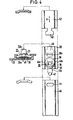
- FIG. 1 a pair of locking elements 10a, 10b; 12a, 12b; 14a, 14b.
- Another pair of locking elements 16a, 16b is intended for fixing an extension arm 18 on the upper frame leg of the casement.
- the displaceable and adjustable locking element 12b is explained in more detail below by the pairing of locking elements 12a, 12b.
- This locking element 12b is arranged on a carrier 20 which, as can be seen from the middle section in FIG. 4, in a C channel 22 is guided on the fold peripheral surface of a casement leg.
- the locking element 12b is guided by guide strips 24 of a slide plate 23 which engage in guide grooves 26 of the carrier 20.
- the guide strips and guide grooves 24, 26 together form a slide guide transverse to the direction of displacement of the carrier 20 in the C-channel 22.
- the locking element 12b is penetrated by an adjusting bolt 28, which has a widening on the exposed end face of the locking element 12b, which in a corresponding depression 30 of a passage 32 of the locking element 12b engages.
- the exposed end face of the adjusting bolt 28 is provided with an Allen recess 34.
- the adjusting bolt 28 passes through an elongated slot 36 of the carrier 20 in the direction of adjustment of the locking element 12b, that is to say in the direction of the slide guide 24, 26, and carries an eccentric disk 38 connected to it at its end located on the rear 20a of the carrier 20 38 is received by an elongated, relief-like recess 40 in the rear 20a of the carrier 20.
- the relief-like recess 40 is elongated in the direction of displacement of the locking element 12b, as can be seen from FIG.
- the eccentric disk 38 engages with eccentric engagement surfaces 40a of the relief-like countersink 40.
- the locking element 12b can be adjusted in the adjustment direction B by turning the adjusting bolt 28.
- the locking element 12b is designed with a coupling pin 42 which sits on the end of the locking element 12b which projects beyond the longitudinal end of the carrier 20 and which engages in an elongated hole 44 which is elongate parallel to the adjustment direction B in a drive rod element 46 .
- the elongated hole formation of the elongated hole 44 is necessary with regard to the adjustability of the locking element 12b.
- the carrier 20 is provided with a dovetail recess 48, into which a dovetail end 50 of the further drive rod element 52 can engage.
- the engagement between the carrier 20 and the drive rod elements 46 and 52 must be made before these parts are inserted into the C-channel 22. Once they have been inserted, they are permanently connected to one another and can be moved together in the direction of movement A.
- connection element of a corner deflection can also occur, which has a corresponding dovetail 50, but is dimensioned in its width so that it can be inserted between the claws of the C channel into the dovetail recess 48, so that one can be inserted Eckumlenkungselements an expansion of the drive rod element 46 and the carrier 20 is not necessary.
- the eccentric disc 38 has a circular outline and a diameter corresponding to the distance between the eccentric engagement surfaces 40a.
Landscapes
- Engineering & Computer Science (AREA)
- Mechanical Engineering (AREA)
- Hinges (AREA)
- Wing Frames And Configurations (AREA)
Applications Claiming Priority (2)
| Application Number | Priority Date | Filing Date | Title |
|---|---|---|---|
| DE19853525705 DE3525705A1 (de) | 1985-07-18 | 1985-07-18 | Paarung von verriegelungselementen an einem fenster einer tuer oder dergleichen |
| DE3525705 | 1985-07-18 |
Publications (1)
| Publication Number | Publication Date |
|---|---|
| EP0208993A1 true EP0208993A1 (de) | 1987-01-21 |
Family
ID=6276117
Family Applications (1)
| Application Number | Title | Priority Date | Filing Date |
|---|---|---|---|
| EP19860109012 Withdrawn EP0208993A1 (de) | 1985-07-18 | 1986-07-02 | Paarung von Verriegelungselementen an einem Fenster, einer Tür oder dergleichen |
Country Status (2)
| Country | Link |
|---|---|
| EP (1) | EP0208993A1 (https=) |
| DE (1) | DE3525705A1 (https=) |
Cited By (2)
| Publication number | Priority date | Publication date | Assignee | Title |
|---|---|---|---|---|
| EP0748911A1 (de) * | 1995-06-13 | 1996-12-18 | Siegenia-Frank Kg | Treibstangen-Verschlussvorrichtung für die Flügel von Fenstern, Türen od. dgl. |
| EP1635019A3 (de) * | 2004-09-11 | 2006-04-12 | Roto Frank Ag | Beschlaganordnung für ein Fenster, eine Tür oder dergleichen |
Families Citing this family (1)
| Publication number | Priority date | Publication date | Assignee | Title |
|---|---|---|---|---|
| DE102019208425B4 (de) * | 2019-06-11 | 2021-04-01 | Roto Frank Fenster- und Türtechnologie GmbH | Stangenförmiges Beschlagelement |
Citations (2)
| Publication number | Priority date | Publication date | Assignee | Title |
|---|---|---|---|---|
| AT312457B (de) * | 1968-12-23 | 1974-01-10 | Siegenia Frank Kg | Flügelverschlußvorrichtung für Fenster, Türen od.dgl. |
| AT318428B (de) * | 1971-10-09 | 1974-10-25 | Siegenia Frank Kg | Riegelvorrichtung an Treibstangenbeschlägen |
Family Cites Families (8)
| Publication number | Priority date | Publication date | Assignee | Title |
|---|---|---|---|---|
| US2231414A (en) * | 1939-10-09 | 1941-02-11 | Elmer L Filter | Strike plate |
| DE1759530A1 (de) * | 1968-05-11 | 1971-06-16 | Siegenia Frank Kg | Schliessblech fuer Fenster- und Tuerverschluesse,insbesondere Kantenverschluesse mit schwenkbaren Riegelzungen |
| DE2301652C3 (de) * | 1973-01-13 | 1984-09-20 | Siegenia-Frank Kg, 5900 Siegen | Ausstellvorrichtung für Drehkippflügel von Fenster, Türen od.dgl. |
| DE2426030C2 (de) * | 1974-05-30 | 1986-09-11 | Winkhaus, August, 4404 Telgte | Ausstellvorrichtung für ein Drehkippfenster |
| DE7623997U1 (de) * | 1976-07-30 | 1979-01-25 | Schaumburg-Lippische Baubeschlagfabrik W. Hautau Gmbh, 3061 Helpsen | Einjustierbares unteres ecklager fuer dreh- und kippfluegel von fenstern, tueren o.dgl. |
| DE2729394C2 (de) * | 1977-06-29 | 1990-08-23 | Fa. Aug. Winkhaus, 4404 Telgte | Verriegelungseinrichtung für Fenster, Türen o.dgl. |
| DE2733710A1 (de) * | 1977-07-26 | 1979-02-01 | Winkhaus Fa August | Verriegelungsvorrichtung fuer fenster, tueren o.dgl. |
| AT374554B (de) * | 1978-06-22 | 1984-05-10 | Frank Gmbh Wilh | Ecklager fuer drehkippfenster od. dgl. |
-
1985
- 1985-07-18 DE DE19853525705 patent/DE3525705A1/de active Granted
-
1986
- 1986-07-02 EP EP19860109012 patent/EP0208993A1/de not_active Withdrawn
Patent Citations (2)
| Publication number | Priority date | Publication date | Assignee | Title |
|---|---|---|---|---|
| AT312457B (de) * | 1968-12-23 | 1974-01-10 | Siegenia Frank Kg | Flügelverschlußvorrichtung für Fenster, Türen od.dgl. |
| AT318428B (de) * | 1971-10-09 | 1974-10-25 | Siegenia Frank Kg | Riegelvorrichtung an Treibstangenbeschlägen |
Cited By (2)
| Publication number | Priority date | Publication date | Assignee | Title |
|---|---|---|---|---|
| EP0748911A1 (de) * | 1995-06-13 | 1996-12-18 | Siegenia-Frank Kg | Treibstangen-Verschlussvorrichtung für die Flügel von Fenstern, Türen od. dgl. |
| EP1635019A3 (de) * | 2004-09-11 | 2006-04-12 | Roto Frank Ag | Beschlaganordnung für ein Fenster, eine Tür oder dergleichen |
Also Published As
| Publication number | Publication date |
|---|---|
| DE3525705C2 (https=) | 1989-01-05 |
| DE3525705A1 (de) | 1987-01-22 |
Similar Documents
| Publication | Publication Date | Title |
|---|---|---|
| EP0335069A1 (de) | Flachschlüssel für Zylinderschlösser sowie zugehöriges Zylinderschloss | |
| EP1857688A2 (de) | Klips- oder Schnappbefestigung zur Festlegung einer dünnen Wand an einen Wandträger | |
| EP0305731B1 (de) | Stulpschienen-Eckverbindung | |
| EP0569818A1 (de) | Scharnierband | |
| DE3645256A1 (de) | Fenster- und Tuerbeschlag | |
| DE2839576A1 (de) | Moebelscharnier, insbesondere verdeckt angeordnetes scharnier | |
| EP0490023A1 (de) | Drucktasteneinrichtung | |
| DE3904210C2 (https=) | ||
| DE19914860B4 (de) | Einrichtung zur Führung und Wegbegrenzung eines Schiebetürelements | |
| DE3627234C2 (https=) | ||
| EP0208993A1 (de) | Paarung von Verriegelungselementen an einem Fenster, einer Tür oder dergleichen | |
| EP1298271A2 (de) | Laufwagenanordnung für einen Beschlag für Hebe-Schiebe-Türen oder -Fenster sowie Beschlag mit einer solchen Laufwagenanordnung | |
| DE202009009459U1 (de) | Mitnehmer zur Anbindung einer Fensterscheibe an einen Fensterheber eines Kraftfahrzeugs | |
| EP0256213B1 (de) | Kippriegelvorrichtung für Drehkippflügel-Fenster und -Türen o.dgl. | |
| DE3908688C2 (de) | Einsteck- oder Kastenschloß für schalldämmende Türen | |
| DE2507910B2 (de) | Fehlbedienungssicherung für das Betätigungsgestänge eines Dreh-Kipp-Fensters | |
| EP0662556B1 (de) | Schlossvorrichtung für eine Tür oder ein Fenster | |
| CH687716A5 (de) | Beschlag. | |
| DE2613772A1 (de) | Schliesszylinder | |
| DE2063689A1 (de) | Mittenvernegelung für ein Fenster | |
| DE102004014509A1 (de) | Treibstangenbeschlag | |
| DE2650667C2 (de) | Ausstellvorrichtung für einen Flügel eines Fensters, einer Tür od.dgl. | |
| DE102015120544B3 (de) | Verstellbares Türband | |
| DE69201079T2 (de) | Schloss für die Harbe eines Motorfahrzeuges versehen mit selbstzentrierenden Mitteln. | |
| DE102005000189A1 (de) | Beschlagteil für einen Treibstangenbeschlag |
Legal Events
| Date | Code | Title | Description |
|---|---|---|---|
| PUAI | Public reference made under article 153(3) epc to a published international application that has entered the european phase |
Free format text: ORIGINAL CODE: 0009012 |
|
| AK | Designated contracting states |
Kind code of ref document: A1 Designated state(s): AT DE FR GB IT SE |
|
| 17P | Request for examination filed |
Effective date: 19870309 |
|
| 17Q | First examination report despatched |
Effective date: 19880324 |
|
| STAA | Information on the status of an ep patent application or granted ep patent |
Free format text: STATUS: THE APPLICATION IS DEEMED TO BE WITHDRAWN |
|
| 18D | Application deemed to be withdrawn |
Effective date: 19880804 |
|
| RIN1 | Information on inventor provided before grant (corrected) |
Inventor name: GREISNER, PAUL Inventor name: MAYER, SIEGFRIED |