EP0205916B1 - Verfahren zur Steuerung und/oder Regelung von Betriebskenngrössen einer Brennkraftmaschine - Google Patents
Verfahren zur Steuerung und/oder Regelung von Betriebskenngrössen einer Brennkraftmaschine Download PDFInfo
- Publication number
- EP0205916B1 EP0205916B1 EP86106798A EP86106798A EP0205916B1 EP 0205916 B1 EP0205916 B1 EP 0205916B1 EP 86106798 A EP86106798 A EP 86106798A EP 86106798 A EP86106798 A EP 86106798A EP 0205916 B1 EP0205916 B1 EP 0205916B1
- Authority
- EP
- European Patent Office
- Prior art keywords
- signal
- combustion engine
- idling
- internal
- value
- Prior art date
- Legal status (The legal status is an assumption and is not a legal conclusion. Google has not performed a legal analysis and makes no representation as to the accuracy of the status listed.)
- Expired
Links
Images
Classifications
-
- F—MECHANICAL ENGINEERING; LIGHTING; HEATING; WEAPONS; BLASTING
- F02—COMBUSTION ENGINES; HOT-GAS OR COMBUSTION-PRODUCT ENGINE PLANTS
- F02D—CONTROLLING COMBUSTION ENGINES
- F02D41/00—Electrical control of supply of combustible mixture or its constituents
- F02D41/02—Circuit arrangements for generating control signals
- F02D41/04—Introducing corrections for particular operating conditions
- F02D41/12—Introducing corrections for particular operating conditions for deceleration
- F02D41/123—Introducing corrections for particular operating conditions for deceleration the fuel injection being cut-off
- F02D41/126—Introducing corrections for particular operating conditions for deceleration the fuel injection being cut-off transitional corrections at the end of the cut-off period
Definitions
- the mixture preparation system known from the first-mentioned document can cause a jolt during the transition from its normal operating state to the operating state of the overrun fuel cutoff, that is to say when the fuel metering to the internal combustion engine is interrupted, which noticeably worsens the driving behavior of the motor vehicle operated with the internal combustion engine .
- the object of the invention with the characterizing features of the main claim has the advantage that the jerk caused by the fuel cut-off during the transition from normal operation of the internal combustion engine to the operating state of the overrun cut-off is avoided in that the fuel is switched off at a very low torque.
- the idle fill signal is influenced in such a way that the idle air supply is reduced in accordance with a signal value (SI, 'tlk) and the injection signal is changed in such a way that the fuel metering is interrupted depending on reaching a certain signal value.
- the idle air supply is set to a value predetermined by the idle charge control so that a possible transition to the idle state can be reacted to quickly.
- a further advantageous development of the invention is characterized in that after the end of the overrun operation, the injection signal is changed in such a way that the interruption of the fuel metering is canceled, and the idling fill signal is influenced in such a way that the idle air supply from a predeterminable low value to a predeterminable average value increases.
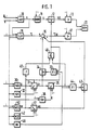
- a signal relating to the air quantity per time QL and a signal relating to the speed of the internal combustion engine N are fed to a load signal formation 10 (LAST).
- a correction device 11 (KORR) connected to the load signal formation 10 forms an output signal as a function of its input signal, the load signal tl, specifically the injection signal ti, which is connected to a switching device 12.
- the output signal of this switching device 12 is denoted by t ik and an output stage 13 supplied, which then affects an internal combustion engine 20.
- An idle control 15 (LLR) is acted upon by the speed signal N and the load signal tl and generates an idle fill signal ⁇ , which is fed to a link 16, as a function thereof.
- This link 16 is fed two further signals negatively, which then together form an output signal which is identified by ⁇ lk and which influences the internal combustion engine 20 via an output stage 17.
- a fuel cut-off detection 30 is acted upon at least by the speed signal N, depending on which it forms an output signal S which drives a fuel cut-off integrator 31.
- This integrator 31 is influenced on the one hand by a fuel cut-off time constant setting 32 (SZK) dependent on the speed N of the internal combustion engine, and on the other hand by a signal W, which will be explained in more detail later.
- the output signal of the integrator 31 is denoted by SI and acts on a switching device 34 controlled by an OR link 33, as well as a threshold value stage 35.
- the threshold value of the threshold value stage 35 is determined by the output signal K of a threshold value setting 36 which is dependent on the engine speed of the internal combustion engine N. (SW) specified.
- a reinsertion detection 40 is triggered by at least one signal with respect to the rotational speed N of the internal combustion engine and generates an output signal W as a function thereof, which is connected to a reinsertion integrator 41.
- This is influenced by a reinsertion time constant setting 42 (WZK) which is dependent on the rotational speed N.
- the output signal of the integrator 41 is identified by WI and acts on a switching device 43 which is controlled by an OR link 44.
- the OR link 44 is connected to the output of the threshold 35, this signal being further connected to an AND link 46.
- the second input of the AND link 46 is influenced by the output signal W of the block 40 via an inverter 45. This signal is also connected to the integrator 31 and to the OR link 33.
- the output signal of the AND link 46 controls the switching device 12 on the one hand and is also connected to the OR link 33 just mentioned.
- a speed gradient detection 48 generates an output signal as a function of the speed signal N, which is connected to one input of each of the two OR links 33 and 44.
- the output signals of the two switching devices 34 and 43 ultimately influence the link 16 provided with a negative sign.
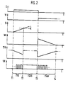
- FIG. 2 shows the course of the signals S, W, SI, Wl, Tlk , and tk.
- the designations T1, T2, T3 and T4 in FIG. 2 are specific points in time, while the abbreviations TVS, TSAS and TVW indicate specific periods of time. In all the diagrams in FIG. 2, the time t is plotted on the horizontal axis.
- the overrun operation of the internal combustion engine is recognized by the overrun fuel cut-off detection 30, so that the signal S jumps from 0 to 1 and the signal SI begins to rise slowly from zero.
- the signal SI is forwarded to the link 16 via the closed switch 34, so that the idle fill signal ⁇ is thereby changed to the signal Tlk . If the signal SI reaches the value K of the threshold value stage 35, this causes a 1 signal at the output of stage 35, which in turn opens all switches 12, 34 and 43. This happens at time T2, which is therefore the actual start of the overrun fuel cutoff.
- the injection signal ti is now interrupted after the time T2, so that the signal t ik is one, which means that no fuel is being injected, and the signal Tlk assumes the value of the idle fill signal TI again, in particular because the switch 34 opens is.
- the time period TVS between the times T1 and T2 is a fuel cut-off delay, while the actual fuel cut-off time TSAS then follows the time T2. This last-mentioned time period ends at time T3.
- signal S becomes zero again, ie there is no overrun fuel cut-off, while signal W becomes 1, which indicates the importance of reinsertion Has overrun cut-off.
- the signal WI is set to a predeterminable output value from which it slowly sinks back to zero, and at the same time the fuel cut-off integrator 31 is reset to the value zero.
- the signal SI falls again below the value K of the threshold value stage 35, with the result that the two switching devices 12 and 43 return to their initial state, namely the closed switching state. Only the switching device 34 remains open because it is controlled via the OR link 33 with the 1 signal of the signal W.
- the injection signal ti is thus passed on via the switching device 12, so that the signal t ik corresponds to the signal ti.
- the signal WI Leerlaufyogllsignal so that the TI is changed by the signal WI towards the Tlk signal is supplied via the switching means 43 of the link 16.
- the time period TVW after the time T3 is an increase in the idle fill signal during the restart, which ended at the time T4.
- the signal WI has become zero again, so that the idle signal ⁇ r now again corresponds to the signal ⁇ k.
- the entire overrun fuel cutoff with subsequent reinstallation is ended.
- the overrun cutoff time constant setting 32 and the reinsertion time constant setting 42 have the task of determining the rise time constants and, if appropriate, also the initial values of the signals SI and WI of the following integrators 31 and 41. Of course, it is also possible for other parameters to act on the two integrators 31 and 41 mentioned. The same is true in connection with the threshold value setting 36.
- This has the task of setting the threshold value K of the threshold value stage 35.
- the value of the signal K is dependent on the speed N of the internal combustion engine. In this context too, it is possible that further parameters act on the threshold value stage 35 and the threshold value setting 36.
- the overrun fuel cutoff detection 30 and the reinsertion detection 40 have the task of recognizing and displaying the overrun operation of the internal combustion engine.
- the detection can be carried out with the aid of the rotational speed N of the internal combustion engine and, if appropriate, further operating parameters of the internal combustion engine. So it is z. B. possible that overrun is present exactly when the throttle valve of the internal combustion engine is in its idle position, but at the same time the speed of the internal combustion engines is at least a certain value above the idle speed.
- the signals ti or t ik and TI or Tlk can be analog as well as digital signals. This is indicated in FIG. 2 by the fact that the signal t ik is shown in the form of individual injection pulses, while the signal ⁇ lk is an analog signal. Ultimately, however, this is insignificant for the invention as such, since the output stages 13 and 17 can be used to convert the injection and idling signals into corresponding control signals of the electromechanical actuators as desired.
- the speed gradient detection 48 has the task of detecting certain predeterminable speed changes in order to then open the switching devices 34 and 43 via the OR links 33 and 44, that is to say to suddenly reset the signal ⁇ lk to the value of the signal ⁇ l . With such certain speed drops, it can be such. B. act a negative speed gradient, which only occurs when the internal combustion engine and the subsequent transmission of the motor vehicle have been decoupled from each other. In this case, it is then through the opening of the switching devices 34 and 43 and the associated reset to the idle fill signal T ; possible that the idle control 15 can optimally adjust the idle speed of the internal combustion engine.
- the engine is first brought to the lowest possible torque by reducing the idle air supply, in order to then interrupt the fuel metering.
- the actual idle fill signal is not changed, it is ensured at every moment of the overrun fuel cutoff that the internal combustion engine does not die during a possible transition to idle operation. The same happens when you reinsert, in which the idle air supply is slowly increased from a low value to its normal value, without again influencing the actual idle control.
- optimal idling control is possible at any moment, even with this transition, while at the same time avoiding the jerk normally caused by the transition.
- Another improvement in driving comfort may consist in the fact that in the event of rapid negative load changes of the internal combustion engine with a subsequent transition to the idle operating state, the fuel cut-off integrator 31 is initially set to a predeterminable negative value, from which the increase in the signal SI, which has hitherto originated from zero, then proceeds.
- the jerk resulting from the closing of the throttle valve can be reduced further, since in the first moment after the throttle valve closes, more air is fed to the internal combustion engine than corresponds to the closed throttle valve.
Landscapes
- Engineering & Computer Science (AREA)
- Chemical & Material Sciences (AREA)
- Combustion & Propulsion (AREA)
- Mechanical Engineering (AREA)
- General Engineering & Computer Science (AREA)
- Electrical Control Of Air Or Fuel Supplied To Internal-Combustion Engine (AREA)
Applications Claiming Priority (2)
| Application Number | Priority Date | Filing Date | Title |
|---|---|---|---|
| DE3521551 | 1985-06-15 | ||
| DE19853521551 DE3521551A1 (de) | 1985-06-15 | 1985-06-15 | Verfahren zur steuerung und/oder regelung von betriebskenngroessen einer brennkraftmaschine |
Publications (3)
| Publication Number | Publication Date |
|---|---|
| EP0205916A2 EP0205916A2 (de) | 1986-12-30 |
| EP0205916A3 EP0205916A3 (en) | 1987-10-28 |
| EP0205916B1 true EP0205916B1 (de) | 1989-08-23 |
Family
ID=6273402
Family Applications (1)
| Application Number | Title | Priority Date | Filing Date |
|---|---|---|---|
| EP86106798A Expired EP0205916B1 (de) | 1985-06-15 | 1986-05-20 | Verfahren zur Steuerung und/oder Regelung von Betriebskenngrössen einer Brennkraftmaschine |
Country Status (5)
| Country | Link |
|---|---|
| US (1) | US4700673A (ja) |
| EP (1) | EP0205916B1 (ja) |
| JP (1) | JPH07103823B2 (ja) |
| BR (1) | BR8602749A (ja) |
| DE (2) | DE3521551A1 (ja) |
Cited By (1)
| Publication number | Priority date | Publication date | Assignee | Title |
|---|---|---|---|---|
| DE19549076A1 (de) * | 1995-12-29 | 1997-07-03 | Opel Adam Ag | Verfahren zur Unterdrückung des beim Übergang von Zug- auf Schubbetrieb auftretenden Ruckelns einer zum Antrieb eines Kraftfahrzeuges dienenden Brennkraftmaschine |
Families Citing this family (10)
| Publication number | Priority date | Publication date | Assignee | Title |
|---|---|---|---|---|
| JPS63212742A (ja) * | 1987-02-27 | 1988-09-05 | Fuji Heavy Ind Ltd | 内燃機関の燃料制御装置 |
| US4977876A (en) * | 1988-03-08 | 1990-12-18 | Nissan Motor Company, Ltd. | Fuel injection control system for internal combustion engine with fuel cut-off control at high engine speed range suppressive of recovery shock upon fuels resumption |
| DE3808692A1 (de) * | 1988-03-16 | 1989-10-05 | Bosch Gmbh Robert | Verfahren zur vermeidung eines zu grossen motorschleppmoments |
| DE3828850A1 (de) * | 1988-08-25 | 1990-03-08 | Bosch Gmbh Robert | Vorrichtung zur steuerung einer betriebskenngroesse einer brennkraftmaschine |
| US5313922A (en) * | 1989-12-23 | 1994-05-24 | Robert Bosch Gmbh | Method for controlling a flow of fuel to an engine of a vehicle during overrun operation |
| DE4332445C2 (de) * | 1993-09-23 | 2002-06-13 | Bayerische Motoren Werke Ag | Verfahren zur Steuerung des Leerlaufstellers einer Brennkraftmaschine |
| DE19518813C1 (de) * | 1995-05-23 | 1996-12-19 | Bosch Gmbh Robert | Verfahren und Vorrichtung zur Steuerung des Drehmoments einer Brennkraftmaschine |
| JP2775676B2 (ja) * | 1996-01-22 | 1998-07-16 | 本田技研工業株式会社 | 内燃機関の燃料供給制御装置 |
| JP2000282923A (ja) * | 1999-03-31 | 2000-10-10 | Nissan Diesel Motor Co Ltd | 内燃機関の燃料噴射量制御装置 |
| DE19943914A1 (de) | 1999-09-14 | 2001-03-15 | Volkswagen Ag | Vorrichtung und Verfahren zum Betreiben einer Brennkraftmaschine mit Drosselklappe im Schubbetrieb |
Family Cites Families (12)
| Publication number | Priority date | Publication date | Assignee | Title |
|---|---|---|---|---|
| US2933168A (en) * | 1957-08-23 | 1960-04-19 | William E Leibing | Deceleration controlled fuel shut-off means |
| US3297103A (en) * | 1964-03-24 | 1967-01-10 | Walker Brooks | Engine fuel supply |
| US3690305A (en) * | 1968-10-04 | 1972-09-12 | Hitachi Ltd | Fuel supply control system for automobile engines |
| US4322947A (en) * | 1977-06-23 | 1982-04-06 | Robert Bosch Gmbh | Control apparatus for a fuel supply system for mixture-compressing, externally ignited internal combustion engines |
| JPS5820374B2 (ja) * | 1977-10-11 | 1983-04-22 | 日産自動車株式会社 | 内燃機関用電子制御燃料噴射装置 |
| DE2801790A1 (de) * | 1978-01-17 | 1979-07-19 | Bosch Gmbh Robert | Verfahren und einrichtung zur steuerung der kraftstoffzufuhr zu einer brennkraftmaschine |
| JPS5512264A (en) * | 1978-07-14 | 1980-01-28 | Toyota Motor Corp | Revolution rate control method for internal-combustion engine |
| EP0089409B1 (de) * | 1982-03-18 | 1989-03-29 | VDO Adolf Schindling AG | Einrichtung zur Abschaltung der Kraftstoffzufuhr zu einem Verbrennungsmotor |
| JPS59150933A (ja) * | 1983-02-15 | 1984-08-29 | Fujitsu Ten Ltd | 電子式燃料噴射装置の噴射制御方法 |
| DE3337786A1 (de) * | 1983-10-18 | 1985-04-25 | Robert Bosch Gmbh, 7000 Stuttgart | Vorrichtung zur steuerung des schubbetriebs einer brennkraftmaschine |
| JPS60100539U (ja) * | 1983-12-15 | 1985-07-09 | 日産自動車株式会社 | 車両用内燃機関の出力制御装置 |
| DE3345711A1 (de) * | 1983-12-17 | 1985-06-27 | Robert Bosch Gmbh, 7000 Stuttgart | Verfahren und vorrichtung zur drehzahlregelung bei einer brennkraftmaschine |
-
1985
- 1985-06-15 DE DE19853521551 patent/DE3521551A1/de not_active Withdrawn
-
1986
- 1986-05-20 EP EP86106798A patent/EP0205916B1/de not_active Expired
- 1986-05-20 DE DE8686106798T patent/DE3665204D1/de not_active Expired
- 1986-05-23 JP JP61117689A patent/JPH07103823B2/ja not_active Expired - Fee Related
- 1986-06-03 US US06/870,131 patent/US4700673A/en not_active Expired - Lifetime
- 1986-06-12 BR BR8602749A patent/BR8602749A/pt not_active IP Right Cessation
Non-Patent Citations (1)
| Title |
|---|
| Bosch, Technische Unterrichtung, Motronic, KH/VDT-09.85-De, S. 20, 21, 26-28 * |
Cited By (1)
| Publication number | Priority date | Publication date | Assignee | Title |
|---|---|---|---|---|
| DE19549076A1 (de) * | 1995-12-29 | 1997-07-03 | Opel Adam Ag | Verfahren zur Unterdrückung des beim Übergang von Zug- auf Schubbetrieb auftretenden Ruckelns einer zum Antrieb eines Kraftfahrzeuges dienenden Brennkraftmaschine |
Also Published As
| Publication number | Publication date |
|---|---|
| US4700673A (en) | 1987-10-20 |
| JPS61291741A (ja) | 1986-12-22 |
| EP0205916A3 (en) | 1987-10-28 |
| DE3665204D1 (en) | 1989-09-28 |
| JPH07103823B2 (ja) | 1995-11-08 |
| BR8602749A (pt) | 1987-02-10 |
| DE3521551A1 (de) | 1986-12-18 |
| EP0205916A2 (de) | 1986-12-30 |
Similar Documents
| Publication | Publication Date | Title |
|---|---|---|
| DE19944044C2 (de) | Verfahren und Vorrichtung zum Steuern eines Motors | |
| DE3020131C2 (ja) | ||
| DE4140527C2 (de) | Regelvorrichtung für das Luft/Brennstoff-Verhältnis für einen Verbrennungsmotor | |
| EP0337987B1 (de) | Elektronische steuereinrichtung zur kraftstoffmengenmodulation eiener brennkraftmaschine | |
| DE2801790A1 (de) | Verfahren und einrichtung zur steuerung der kraftstoffzufuhr zu einer brennkraftmaschine | |
| DE2842389A1 (de) | Vorrichtung zur einstellung des drehmomentes einer brennkraftmaschine | |
| DE3539395A1 (de) | Verfahren und einrichtung zur adaption der gemischsteuerung bei brennkraftmaschinen | |
| EP0205916B1 (de) | Verfahren zur Steuerung und/oder Regelung von Betriebskenngrössen einer Brennkraftmaschine | |
| DE3138099A1 (de) | Verfahren zur steuerung der ansaugluft bei einer brennkraftmaschine | |
| EP0347446B1 (de) | Verfahren und einrichtung zur beeinflussung der luftzumessung bei einer brennkraftmaschine, insbesondere im leerlauf und schubbetrieb | |
| DE2939520C2 (de) | Verfahren und Vorrichtung zum elektronischen Steuern der Kraftstoffeinspritzung und des Zündzeitpunkts bei einer Brennkraftmaschine | |
| EP0819210A1 (de) | Verfahren zum ermitteln einer einspritzmehrmenge beim wiedereinsetzen einer brennkraftmaschine | |
| EP0130341A2 (de) | Verfahren und Vorrichtung zur Steuerung des Schubbetriebs einer Brennkraftmaschine | |
| DE4417802B4 (de) | Vorrichtung zur Regelung der Motorleistung oder der Fahrgeschwindigkeit eines Fahrzeugs | |
| DE3048626C2 (ja) | ||
| EP0168412A1 (de) | Verfahren und vorrichtung zur drehzahlregelung bei einer brennkraftmaschine | |
| EP1005609B1 (de) | Verfahren zur steuerung der abgasrückführung bei einer brennkraftmaschine | |
| DE3919108C2 (de) | Verfahren zur Steuerung eines Betriebsparameters eines Kraftfahrzeugs bei dynamischen Betriebszuständen | |
| DE4234970C2 (de) | Vorrichtung und Verfahren zum Steuern einer Brennkraftmaschine | |
| DE3014842A1 (de) | Brennkraftmaschine | |
| DE3628628C2 (de) | Verfahren und Einrichtung zur Adaption der Gemischsteuerung bei Brennkraftmaschinen | |
| EP0074540B1 (de) | Verfahren zum Betrieb und Einrichtung für ein Kraftstoffsteuersystem einer Brennkraftmaschine bei Schubbetrieb | |
| DE19926351C2 (de) | Vorrichtung zur Drehzahlbegrenzung von Motoren und/oder zur Geschwindigkeitsbegrenzung von motorbetriebenen Kraftfahrzeugen | |
| DE4105161C2 (de) | Einrichtung zur Regelung der Leerlaufdrehzahl eines Motors eines Kraftfahrzeugs | |
| EP1045122B1 (de) | Vorrichtung zur Drehzahlbegrenzung von Motoren und/oder Geschwindigkeitsbegrenzung von motorbetriebenen Kraftfahrzeugen |
Legal Events
| Date | Code | Title | Description |
|---|---|---|---|
| PUAI | Public reference made under article 153(3) epc to a published international application that has entered the european phase |
Free format text: ORIGINAL CODE: 0009012 |
|
| AK | Designated contracting states |
Kind code of ref document: A2 Designated state(s): DE FR GB SE |
|
| PUAL | Search report despatched |
Free format text: ORIGINAL CODE: 0009013 |
|
| AK | Designated contracting states |
Kind code of ref document: A3 Designated state(s): DE FR GB SE |
|
| 17P | Request for examination filed |
Effective date: 19880323 |
|
| 17Q | First examination report despatched |
Effective date: 19880902 |
|
| GRAA | (expected) grant |
Free format text: ORIGINAL CODE: 0009210 |
|
| AK | Designated contracting states |
Kind code of ref document: B1 Designated state(s): DE FR GB SE |
|
| GBT | Gb: translation of ep patent filed (gb section 77(6)(a)/1977) | ||
| REF | Corresponds to: |
Ref document number: 3665204 Country of ref document: DE Date of ref document: 19890928 |
|
| ET | Fr: translation filed | ||
| PLBE | No opposition filed within time limit |
Free format text: ORIGINAL CODE: 0009261 |
|
| STAA | Information on the status of an ep patent application or granted ep patent |
Free format text: STATUS: NO OPPOSITION FILED WITHIN TIME LIMIT |
|
| 26N | No opposition filed | ||
| EAL | Se: european patent in force in sweden |
Ref document number: 86106798.1 |
|
| PGFP | Annual fee paid to national office [announced via postgrant information from national office to epo] |
Ref country code: GB Payment date: 19950426 Year of fee payment: 10 |
|
| PGFP | Annual fee paid to national office [announced via postgrant information from national office to epo] |
Ref country code: FR Payment date: 19950512 Year of fee payment: 10 |
|
| PGFP | Annual fee paid to national office [announced via postgrant information from national office to epo] |
Ref country code: SE Payment date: 19950522 Year of fee payment: 10 |
|
| PG25 | Lapsed in a contracting state [announced via postgrant information from national office to epo] |
Ref country code: GB Effective date: 19960520 |
|
| PG25 | Lapsed in a contracting state [announced via postgrant information from national office to epo] |
Ref country code: SE Effective date: 19960521 |
|
| GBPC | Gb: european patent ceased through non-payment of renewal fee |
Effective date: 19960520 |
|
| PG25 | Lapsed in a contracting state [announced via postgrant information from national office to epo] |
Ref country code: FR Effective date: 19970131 |
|
| EUG | Se: european patent has lapsed |
Ref document number: 86106798.1 |
|
| REG | Reference to a national code |
Ref country code: FR Ref legal event code: ST |
|
| PGFP | Annual fee paid to national office [announced via postgrant information from national office to epo] |
Ref country code: DE Payment date: 20040712 Year of fee payment: 19 |
|
| PG25 | Lapsed in a contracting state [announced via postgrant information from national office to epo] |
Ref country code: DE Free format text: LAPSE BECAUSE OF NON-PAYMENT OF DUE FEES Effective date: 20051201 |