EP0205916B1 - Method for controlling and/or regulating the operating caracteristics of a combustion engine - Google Patents
Method for controlling and/or regulating the operating caracteristics of a combustion engine Download PDFInfo
- Publication number
- EP0205916B1 EP0205916B1 EP86106798A EP86106798A EP0205916B1 EP 0205916 B1 EP0205916 B1 EP 0205916B1 EP 86106798 A EP86106798 A EP 86106798A EP 86106798 A EP86106798 A EP 86106798A EP 0205916 B1 EP0205916 B1 EP 0205916B1
- Authority
- EP
- European Patent Office
- Prior art keywords
- signal
- combustion engine
- idling
- internal
- value
- Prior art date
- Legal status (The legal status is an assumption and is not a legal conclusion. Google has not performed a legal analysis and makes no representation as to the accuracy of the status listed.)
- Expired
Links
Images
Classifications
-
- F—MECHANICAL ENGINEERING; LIGHTING; HEATING; WEAPONS; BLASTING
- F02—COMBUSTION ENGINES; HOT-GAS OR COMBUSTION-PRODUCT ENGINE PLANTS
- F02D—CONTROLLING COMBUSTION ENGINES
- F02D41/00—Electrical control of supply of combustible mixture or its constituents
- F02D41/02—Circuit arrangements for generating control signals
- F02D41/04—Introducing corrections for particular operating conditions
- F02D41/12—Introducing corrections for particular operating conditions for deceleration
- F02D41/123—Introducing corrections for particular operating conditions for deceleration the fuel injection being cut-off
- F02D41/126—Introducing corrections for particular operating conditions for deceleration the fuel injection being cut-off transitional corrections at the end of the cut-off period
Definitions
- the mixture preparation system known from the first-mentioned document can cause a jolt during the transition from its normal operating state to the operating state of the overrun fuel cutoff, that is to say when the fuel metering to the internal combustion engine is interrupted, which noticeably worsens the driving behavior of the motor vehicle operated with the internal combustion engine .
- the object of the invention with the characterizing features of the main claim has the advantage that the jerk caused by the fuel cut-off during the transition from normal operation of the internal combustion engine to the operating state of the overrun cut-off is avoided in that the fuel is switched off at a very low torque.
- the idle fill signal is influenced in such a way that the idle air supply is reduced in accordance with a signal value (SI, 'tlk) and the injection signal is changed in such a way that the fuel metering is interrupted depending on reaching a certain signal value.
- the idle air supply is set to a value predetermined by the idle charge control so that a possible transition to the idle state can be reacted to quickly.
- a further advantageous development of the invention is characterized in that after the end of the overrun operation, the injection signal is changed in such a way that the interruption of the fuel metering is canceled, and the idling fill signal is influenced in such a way that the idle air supply from a predeterminable low value to a predeterminable average value increases.
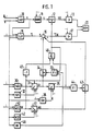
- a signal relating to the air quantity per time QL and a signal relating to the speed of the internal combustion engine N are fed to a load signal formation 10 (LAST).
- a correction device 11 (KORR) connected to the load signal formation 10 forms an output signal as a function of its input signal, the load signal tl, specifically the injection signal ti, which is connected to a switching device 12.
- the output signal of this switching device 12 is denoted by t ik and an output stage 13 supplied, which then affects an internal combustion engine 20.
- An idle control 15 (LLR) is acted upon by the speed signal N and the load signal tl and generates an idle fill signal ⁇ , which is fed to a link 16, as a function thereof.
- This link 16 is fed two further signals negatively, which then together form an output signal which is identified by ⁇ lk and which influences the internal combustion engine 20 via an output stage 17.
- a fuel cut-off detection 30 is acted upon at least by the speed signal N, depending on which it forms an output signal S which drives a fuel cut-off integrator 31.
- This integrator 31 is influenced on the one hand by a fuel cut-off time constant setting 32 (SZK) dependent on the speed N of the internal combustion engine, and on the other hand by a signal W, which will be explained in more detail later.
- the output signal of the integrator 31 is denoted by SI and acts on a switching device 34 controlled by an OR link 33, as well as a threshold value stage 35.
- the threshold value of the threshold value stage 35 is determined by the output signal K of a threshold value setting 36 which is dependent on the engine speed of the internal combustion engine N. (SW) specified.
- a reinsertion detection 40 is triggered by at least one signal with respect to the rotational speed N of the internal combustion engine and generates an output signal W as a function thereof, which is connected to a reinsertion integrator 41.
- This is influenced by a reinsertion time constant setting 42 (WZK) which is dependent on the rotational speed N.
- the output signal of the integrator 41 is identified by WI and acts on a switching device 43 which is controlled by an OR link 44.
- the OR link 44 is connected to the output of the threshold 35, this signal being further connected to an AND link 46.
- the second input of the AND link 46 is influenced by the output signal W of the block 40 via an inverter 45. This signal is also connected to the integrator 31 and to the OR link 33.
- the output signal of the AND link 46 controls the switching device 12 on the one hand and is also connected to the OR link 33 just mentioned.
- a speed gradient detection 48 generates an output signal as a function of the speed signal N, which is connected to one input of each of the two OR links 33 and 44.
- the output signals of the two switching devices 34 and 43 ultimately influence the link 16 provided with a negative sign.
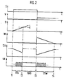
- FIG. 2 shows the course of the signals S, W, SI, Wl, Tlk , and tk.
- the designations T1, T2, T3 and T4 in FIG. 2 are specific points in time, while the abbreviations TVS, TSAS and TVW indicate specific periods of time. In all the diagrams in FIG. 2, the time t is plotted on the horizontal axis.
- the overrun operation of the internal combustion engine is recognized by the overrun fuel cut-off detection 30, so that the signal S jumps from 0 to 1 and the signal SI begins to rise slowly from zero.
- the signal SI is forwarded to the link 16 via the closed switch 34, so that the idle fill signal ⁇ is thereby changed to the signal Tlk . If the signal SI reaches the value K of the threshold value stage 35, this causes a 1 signal at the output of stage 35, which in turn opens all switches 12, 34 and 43. This happens at time T2, which is therefore the actual start of the overrun fuel cutoff.
- the injection signal ti is now interrupted after the time T2, so that the signal t ik is one, which means that no fuel is being injected, and the signal Tlk assumes the value of the idle fill signal TI again, in particular because the switch 34 opens is.
- the time period TVS between the times T1 and T2 is a fuel cut-off delay, while the actual fuel cut-off time TSAS then follows the time T2. This last-mentioned time period ends at time T3.
- signal S becomes zero again, ie there is no overrun fuel cut-off, while signal W becomes 1, which indicates the importance of reinsertion Has overrun cut-off.
- the signal WI is set to a predeterminable output value from which it slowly sinks back to zero, and at the same time the fuel cut-off integrator 31 is reset to the value zero.
- the signal SI falls again below the value K of the threshold value stage 35, with the result that the two switching devices 12 and 43 return to their initial state, namely the closed switching state. Only the switching device 34 remains open because it is controlled via the OR link 33 with the 1 signal of the signal W.
- the injection signal ti is thus passed on via the switching device 12, so that the signal t ik corresponds to the signal ti.
- the signal WI Leerlaufyogllsignal so that the TI is changed by the signal WI towards the Tlk signal is supplied via the switching means 43 of the link 16.
- the time period TVW after the time T3 is an increase in the idle fill signal during the restart, which ended at the time T4.
- the signal WI has become zero again, so that the idle signal ⁇ r now again corresponds to the signal ⁇ k.
- the entire overrun fuel cutoff with subsequent reinstallation is ended.
- the overrun cutoff time constant setting 32 and the reinsertion time constant setting 42 have the task of determining the rise time constants and, if appropriate, also the initial values of the signals SI and WI of the following integrators 31 and 41. Of course, it is also possible for other parameters to act on the two integrators 31 and 41 mentioned. The same is true in connection with the threshold value setting 36.
- This has the task of setting the threshold value K of the threshold value stage 35.
- the value of the signal K is dependent on the speed N of the internal combustion engine. In this context too, it is possible that further parameters act on the threshold value stage 35 and the threshold value setting 36.
- the overrun fuel cutoff detection 30 and the reinsertion detection 40 have the task of recognizing and displaying the overrun operation of the internal combustion engine.
- the detection can be carried out with the aid of the rotational speed N of the internal combustion engine and, if appropriate, further operating parameters of the internal combustion engine. So it is z. B. possible that overrun is present exactly when the throttle valve of the internal combustion engine is in its idle position, but at the same time the speed of the internal combustion engines is at least a certain value above the idle speed.
- the signals ti or t ik and TI or Tlk can be analog as well as digital signals. This is indicated in FIG. 2 by the fact that the signal t ik is shown in the form of individual injection pulses, while the signal ⁇ lk is an analog signal. Ultimately, however, this is insignificant for the invention as such, since the output stages 13 and 17 can be used to convert the injection and idling signals into corresponding control signals of the electromechanical actuators as desired.
- the speed gradient detection 48 has the task of detecting certain predeterminable speed changes in order to then open the switching devices 34 and 43 via the OR links 33 and 44, that is to say to suddenly reset the signal ⁇ lk to the value of the signal ⁇ l . With such certain speed drops, it can be such. B. act a negative speed gradient, which only occurs when the internal combustion engine and the subsequent transmission of the motor vehicle have been decoupled from each other. In this case, it is then through the opening of the switching devices 34 and 43 and the associated reset to the idle fill signal T ; possible that the idle control 15 can optimally adjust the idle speed of the internal combustion engine.
- the engine is first brought to the lowest possible torque by reducing the idle air supply, in order to then interrupt the fuel metering.
- the actual idle fill signal is not changed, it is ensured at every moment of the overrun fuel cutoff that the internal combustion engine does not die during a possible transition to idle operation. The same happens when you reinsert, in which the idle air supply is slowly increased from a low value to its normal value, without again influencing the actual idle control.
- optimal idling control is possible at any moment, even with this transition, while at the same time avoiding the jerk normally caused by the transition.
- Another improvement in driving comfort may consist in the fact that in the event of rapid negative load changes of the internal combustion engine with a subsequent transition to the idle operating state, the fuel cut-off integrator 31 is initially set to a predeterminable negative value, from which the increase in the signal SI, which has hitherto originated from zero, then proceeds.
- the jerk resulting from the closing of the throttle valve can be reduced further, since in the first moment after the throttle valve closes, more air is fed to the internal combustion engine than corresponds to the closed throttle valve.
Description
Die Erfindung betrifft ein Verfahren zur Steuerung und/oder Regelung von Betriebskenngrößen einer Brennkraftmaschine mit den Merkmalen nach Anspruch 1, erster Teil (vergleiche Bosch, Technische Unterrichtung, Motronic (KH-VDT - 09.85 - DE)).The invention relates to a method for the control and / or regulation of operating parameters of an internal combustion engine with the features of
Aus Bosch, Technische Unterrichtung, Motronic (KH/VDT - 09.85 - De), ist bekannt, das Einspritzsignal für die Zumessung des Kraftstoffs zur Brennkraftmaschine in Abhängigkeit von Betriebskenngrößen zu bilden, die Luftzufuhr zur Brennkraftmaschine im Leerlauf durch eine Leerlauffüllungsregelung in Abhängigkeit von Betriebskenngrößen zu regeln sowie bei erkanntem Schubbetrieb der Brennkraftmaschine zum Zweck der Benzinersparnis die Kraftstoffzumessung zur Brennkraftmaschine zu unterbrechen, indem das Einspritzsignal für die Zumessung von Kraftstoff zur Brennkraftmaschine derart beeinflußt wird, daß die Kraftstoffzumessung unterbleibt. Am Ende des Schubbetriebs wird dieser Vorgang dann wieder rückgängig gemacht, so daß danach ein normaler Betrieb der Brennkraftmaschine wieder möglich ist.From Bosch, Technical Instruction, Motronic (KH / VDT - 09.85 - De), it is known to form the injection signal for metering the fuel to the internal combustion engine as a function of operating parameters, and to supply the air to the internal combustion engine at idle using an idling charge control as a function of operating parameters regulate and interrupt the fuel metering to the internal combustion engine when the overrun operation of the internal combustion engine is detected for the purpose of saving gasoline by influencing the injection signal for metering fuel to the internal combustion engine in such a way that the fuel metering is omitted. At the end of the overrun operation, this process is then reversed, so that normal operation of the internal combustion engine is then possible again.
Aus der DE-OS-2 749 369 ist ein Regelsystem zur Regelung der Leerlaufdrehzahl über die Luftzufuhr zur Brennkraftmaschine bekannt, das zur Verbesserung des Übergangs vom Schubbetrieb in den Leerlaufzustand den Ausgang der Regelung und somit die Stellung des Stellgliedes im Schubbetrieb auf einen mittleren Pegel steuert. Eine Verbesserung des Übergangs von Fahrbetrieb in Schubbetrieb kann so nicht erreicht werden.From DE-OS-2 749 369 a control system for controlling the idle speed via the air supply to the internal combustion engine is known, which controls the output of the control and thus the position of the actuator in overrun to an intermediate level to improve the transition from coasting to idling . An improvement in the transition from driving to pushing operation cannot be achieved in this way.
Aus der DE-OS-2 801 790 ist schließlich ein Verfahren zur Steuerung der Kraftstoffzufuhr zu einer Brennkraftmaschine im Schubbetrieb bekannt, das die Kraftstoffzufuhr mit Beginn des Schubbetriebs nach einer wählbaren Funktion zurücknimmt und abschaltet. Auf diese Art sollen weiche Übergänge in und aus dem Schubbetrieb erreicht werden. Diesem Verfahren sind jedoch durch die mangelnde Zündfähigkeit des Gemisches unterhalb einer bestimmten Kraftstoffmenge Grenzen gesetzt.From DE-OS-2 801 790 a method for controlling the fuel supply to an internal combustion engine in overrun mode is finally known, which reduces the fuel supply at the beginning of the overrun mode and switches it off after a selectable function. In this way, smooth transitions into and out of overrun are to be achieved. However, this method is limited by the lack of ignitability of the mixture below a certain amount of fuel.
Es hat sich jedoch gezeigt, daß insbesondere das aus dem zuerst genannten Dokument bekannte Gemischaufbereitungssystem beim Übergang von ihrem normalen Betriebszustand zum Betriebszustand der Schubabschaltung, also beim Unterbrechen der Kraftstoffzumessung zur Brennkraftmaschine einen Ruck hervorrufen kann, der das Fahrverhalten des mit der Brennkraftmaschine betriebenen Kraftfahrzeugs spürbar verschlechtert.However, it has been shown that, in particular, the mixture preparation system known from the first-mentioned document can cause a jolt during the transition from its normal operating state to the operating state of the overrun fuel cutoff, that is to say when the fuel metering to the internal combustion engine is interrupted, which noticeably worsens the driving behavior of the motor vehicle operated with the internal combustion engine .
Es ist daher die Aufgabe der nachstehenden Erfindung, diesen Kraftstoffabschaltruck bzw. -wiedereinsetzruck zu vermindern und so das Fahrverhalten des Kraftfahrzeuges zu verbessern.It is therefore the object of the following invention to reduce this fuel shutdown jerk or re-use jerk and thus to improve the driving behavior of the motor vehicle.
Der erfindungsgemäße Gegenstand mit den kennzeichnenden Merkmalen des Hauptanspruchs weist den Vorteil auf, daß der durch die Kraftstoffabschaltung hervorgerufene Ruck beim Übergang vom Normalbetrieb der Brennkraftmaschine zum Betriebszustand der Schubabschaltung dadurch vermieden wird, daß der Kraftstoff bei sehr geringem Drehmoment abgeschaltet wird. Dies wird dadurch erreicht, daß nach dem Beginn des Schubbetriebs das Leerlauffüllsignal derart beeinflußt wird, daß sich die Leerlaufluftzufuhr entsprechend einem Signalwert (SI, 'tlk) vermindert und abhängig vom Erreichen eines bestimmten Signalwertes das Einspritzsignal derart verändert wird, daß die Kraftstoffzumessung unterbrochen ist.The object of the invention with the characterizing features of the main claim has the advantage that the jerk caused by the fuel cut-off during the transition from normal operation of the internal combustion engine to the operating state of the overrun cut-off is avoided in that the fuel is switched off at a very low torque. This is achieved in that after the start of the overrun operation, the idle fill signal is influenced in such a way that the idle air supply is reduced in accordance with a signal value (SI, 'tlk) and the injection signal is changed in such a way that the fuel metering is interrupted depending on reaching a certain signal value.
Bei unterbrochener Kraftstoffzufuhr wird die Leerlaufluftzufuhr auf einem von der Leerlauffüllungsregelung vorbestimmten Wert festgelegt, so daß auf einen möglichen Übergang in den Leerlaufzustand schnell reagiert werden kann.If the fuel supply is interrupted, the idle air supply is set to a value predetermined by the idle charge control so that a possible transition to the idle state can be reacted to quickly.
Eine weitere vorteilhafte Weiterbildung der Erfindung ist dadurch gekennzeichnet, daß naeh dem Ende des Schubbetriebs das Einspritzsignal derart verändert wird, daß die Unterbrechung der Kraftstoffzumessung aufgehoben ist, und das Leerlauffüllsignal derart beeinflußt wird, daß die Leerlaufluftzufuhr von einem vorbestimmbaren niederen Wert auf einen vorbestimmbaren mittleren Wert ansteigt. Durch diese Maßnahme wird erreicht, daß der Übergang vom Betriebszustand der Schubabschaltung zum normalen Betrieb der Brennkraftmaschine ebenfalls ohne einen das Fahrverhalten störenden Ruck vor sich geht.A further advantageous development of the invention is characterized in that after the end of the overrun operation, the injection signal is changed in such a way that the interruption of the fuel metering is canceled, and the idling fill signal is influenced in such a way that the idle air supply from a predeterminable low value to a predeterminable average value increases. This measure ensures that the transition from the operating state of the overrun fuel cutoff to the normal operation of the internal combustion engine also takes place without a jolt that disturbs the driving behavior.
Weitere vorteilhafte Ausgestaltungen und Weiterbildungen der Erfindung ergeben sich aus den Unteransprüchen, sowie aus der Zeichnung mit der zugehörigen Beschreibung. Dabei weist die Zeichnung zwei Figuren auf, von denen Figur 1 ein Blockschaltbild für die Ausführung des erfindungsgemäßen Verfahrens zeigt und Figur 2 Signaldiagramme zum Blockschaltbild der Figur 1 darstellt. Beide Figuren sind in der nachfolgenden Beschreibung näher erläutert.Further advantageous refinements and developments of the invention result from the subclaims and from the drawing with the associated description. The drawing has two figures, of which FIG. 1 shows a block diagram for the implementation of the method according to the invention and FIG. 2 shows signal diagrams for the block diagram of FIG. 1. Both figures are explained in more detail in the description below.
In der Figur 1 wird einer Lastsignalbildung 10 (LAST) ein Signal bezüglich der Luftmenge pro Zeit QL und ein Signal bezüglich der Drehzahl der Brennkraftmaschine N zugeführt. Eine an die Lastsignalbildung 10 angeschlossene Korrektureinrichtung 11 (KORR) bildet in Abhängigkeit von ihren Eingangssignal, dem Lastsignal tl ein Ausgangssignal, und zwar das Einspritzsignal ti, das an eine Schalteinrichtung 12 angeschlossen ist. Das Ausgangssignal dieser Schalteinrichtung 12 ist mit tik bezeichnet und einer Endstufe 13 zugeführt, die dann eine Brennkraftmaschine 20 beeinflußt.In FIG. 1, a signal relating to the air quantity per time QL and a signal relating to the speed of the internal combustion engine N are fed to a load signal formation 10 (LAST). A correction device 11 (KORR) connected to the
Eine Leerlaufregelung 15 (LLR) ist von dem Drehzahlsignal N und dem Lastsignal tl beaufschlagt und erzeugt in Abhängigkeit davon ein Leerlauffüllsignal τ, das einer Verknüpfung 16 zugeführt ist. Dieser Verknüpfung 16 sind noch zwei weitere Signale negativ zugeführt, die dann zusammen ein Ausgangssignal bilden, das mit τlk gekennzeichnet ist, und das über eine Endstufe 17 die Brennkraftmaschine 20 beeinflußt.An idle control 15 (LLR) is acted upon by the speed signal N and the load signal tl and generates an idle fill signal τ, which is fed to a
Die bisher beschriebene Anordnung ist an sich bekannt und kann von einem Fachmann in vielerlei Hinsicht modifiziert werden. Die spezielle Ausführung eines derartigen Gemischaufbereitungssystems ist jedoch für die Erfindung auch nicht wesentlich. Wichtig sind bisher nur die Schalteinrichtung 12 und die Verknüpfung 16, über die die nachfolgend beschriebene Erfindung in das bekannte System eingreift.The arrangement described so far is known per se and can be modified in many ways by a person skilled in the art. However, the special design of such a mixture preparation system is also not essential for the invention. So far, only the
Eine Schubabschaltungs-Erkennung 30 (SAS) ist zumindest mit dem Drehzahlsignal N beaufschlagt, in dessen Abhängigkeit sie ein Ausgangssignal S bildet, das einen Schubabschaltungs-Integrator 31 ansteuert. Dieser Integrator 31 wird dabei zum einen von einer von der Drehzahl N der Brennkraftmaschine abhängigen Schubabschaltungs-Zeitkonstante-Einstellung 32 (SZK), sowie zum anderen von einem Signal W beeinflußt, das später noch genauer erläutert werden wird. Das Ausgangssignal des Integrators 31 ist mit SI bezeichnet und beaufschlagt eine von einer ODER-Verknüpfung 33 angesteuerte Schalteinrichtung 34, sowie eine Schwellwertstufe 35. Der Schwellwert der Schwellwertstufe 35 wird dabei durch das Ausgangssignal K einer von der Maschinendrehzahl der Brennkraftmaschine N abhängigen Schwellwert-Einstellung 36 (SW) vorgegeben.A fuel cut-off detection 30 (SAS) is acted upon at least by the speed signal N, depending on which it forms an output signal S which drives a fuel cut-off integrator 31. This integrator 31 is influenced on the one hand by a fuel cut-off time constant setting 32 (SZK) dependent on the speed N of the internal combustion engine, and on the other hand by a signal W, which will be explained in more detail later. The output signal of the integrator 31 is denoted by SI and acts on a
Eine Wiedereinsetz-Erkennung 40 (WES) wird wenigstens von einem Signal bezüglich der Drehzahl N der Brennkraftmaschine angesteuert und erzeugt in Abhängigkeit davon ein Ausgangssignal W, das an einem Wiedereinsetz-Integrator 41 angeschlossen ist. Dieser wird von einer von der Drehzahl N abhängigen Wiedereinsetz-Zeitkonstanten-Einstellung 42 (WZK) beeinflußt. Das Ausgangssignal des Integrators 41 ist mit WI gekennzeichnet und beaufschlagt eine Schalteinrichtung 43, die von einer ODER-Verknüpfung 44 gesteuert wird. An einem seiner Eingänge ist die ODER-Verknüpfung 44 mit dem Ausgang der Schwellwertstufe 35 verbunden, wobei dieses Signal des weiteren an eine UND-Verknüpfung 46 angeschlossen ist. Der zweite Eingang der UND-Verknüpfung 46 wird über einen Inverter 45 vom Ausgangssignal W des Blocks 40 beeinflußt. Dieses Signal ist des weiteren an den Integrator 31, sowie an die ODER-Verknüpfung 33 angeschlossen. Das Ausgangssignal der UND-Verknüpfung 46 steuert zum einen die Schalteinrichtung 12 und ist des weiteren mit der eben genannten ODER-Verknüpfung 33 verbunden.A reinsertion detection 40 (WES) is triggered by at least one signal with respect to the rotational speed N of the internal combustion engine and generates an output signal W as a function thereof, which is connected to a reinsertion integrator 41. This is influenced by a reinsertion time constant setting 42 (WZK) which is dependent on the rotational speed N. The output signal of the integrator 41 is identified by WI and acts on a
Schließlich erzeugt eine Drehzahl-Gradienten-Erkennung 48 (DG) in Abhängigkeit vom Drehzahlsignal N ein Ausgangssignal, das an jeweils einen Eingang der beiden ODER-Verknüpfungen 33 und 44 angeschlossen ist. Die Ausgangssignale der beiden Schalteinrichtungen 34 und 43 beeinflussen zuletzt mit einem negativen Vorzeichen versehen die Verknüpfung 16.Finally, a speed gradient detection 48 (DG) generates an output signal as a function of the speed signal N, which is connected to one input of each of the two
Die Funktionsweise des in der Figur 1 dargestellten Blockschaltbilds soll nachfolgend mit Hilfe der Signaldiagramme der Figur 2 erläutert werden. Diese Figur 2 zeigt dabei den Verlauf der Signale S, W, SI, Wl, Tlk, sowie tk. Bei den Bezeichnungen T1, T2, T3 und T4 handelt es sich in der Figur 2 um bestimmte Zeitpunkte, während die Abkürzungen TVS, TSAS und TVW bestimmte Zeitdauern kennzeichnen. Bei sämtlichen Diagrammen der Figur 2 ist auf der horizontalen Achse die Zeit t aufgetragen.The mode of operation of the block diagram shown in FIG. 1 will be explained below with the aid of the signal diagrams in FIG. 2. This Figure 2 shows the course of the signals S, W, SI, Wl, Tlk , and tk. The designations T1, T2, T3 and T4 in FIG. 2 are specific points in time, while the abbreviations TVS, TSAS and TVW indicate specific periods of time. In all the diagrams in FIG. 2, the time t is plotted on the horizontal axis.
Vor dem Zeitpunkt T1 findet noch keine Schubabschaltung statt. Dies hat zur Folge, daß die beiden Signale S und W und dadurch auch die beiden Signale SI und WI jeweils Null sind. Da das Ausgangssignal der Drehzahl-Gradienten-Erkennung 48 im Normalfall immer Null ist, und da des weiteren die Schwelle K der Schwellwertstufe 35 größer als Null ist, sind sämtliche Schalter 12, 34 und 43 geschlossen. Über die beiden zuletzt genannten Schalter 34 und 43 wird jedoch kein Signal an die Verknüpfung 16 weitergeleitet. Insgesamt wird also vor dem Zeitpunkt T1 die Brennkraftmaschine einzig durch das Einspritzsignal ti und das Leerlauffüllsignal i; beeinflußt, da über die Schalteinrichtung 12 und die Verknüpfung 16 keine Veränderungen dieser Signale hervorgerufen werden.There is no overrun fuel cutoff before time T1. The result of this is that the two signals S and W, and therefore also the two signals SI and WI, are each zero. Since the output signal of the
Im Zeitpunkt T1 wird der Schubbetrieb der Brennkraftmaschine von der Schubabschaltungs- Erkennung 30 erkannt, so daß das Signal S von 0 auf 1 springt und das Signal SI langsam vom Wert Null ausgehend zu steigen beginnt. Über den geschlossenen Schalter 34 wird das Signal SI an die Verknüpfung 16 weitergeleitet, so daß dadurch das Leerlauffüllsignal τ hin zum Signal Tlk verändert wird. Erreicht das Signal SI den Wert K der Schwellwertstufe 35, so bewirkt dies am Ausgang der Stufe 35 ein 1-Signal, das seinerseits wiederum sämtliche Schalter 12, 34 und 43 öffnet. Dies geschieht im Zeitpunkt T2, bei dem es sich daher um den eigentlichen Anfang der Schubabschaltung handelt. Es ist also jetzt nach dem Zeitpunkt T2 das Einspritzsignal ti unterbrochen, so daß das Signal tik Eins ist, was bedeutet, daß kein Kraftstoff eingespritzt wird, und das Signal Tlk nimmt den Wert des Leerlauffüllsignals TI wieder an, da insbesondere der Schalter 34 geöffnet ist. Bei der Zeitdauer TVS zwischen den Zeitpunkten T1 und T2 handelt es sich um eine Schubabschalt-Verzögerung, während dann dem Zeitpunkt T2 die eigentliche Schubabschalt-Dauer TSAS folgt. Diese zuletzt genannte Zeitdauer wird im Zeitpunkt T3 beendet.At time T1, the overrun operation of the internal combustion engine is recognized by the overrun fuel cut-
Im Zeitpunkt T3 wird das Signal S wieder zu Null, d.h. es liegt keine Schubabschaltung mehr vor, während das Signal W zu 1 wird, was die Bedeutung eines Wiedereinsetzens nach Schubabschaltung hat. Aufgrund des jetzt vorliegenden, von 0 ungleichen Signals W wird das Signal WI auf einen vorbestimmbaren Ausgangswert gesetzt, von dem aus es langsam auf den Wert Null wieder absinkt, und gleichzeitig wird der Schubabschaltungs-Integrator 31 wieder auf den Wert Null zurückgesetzt. Dadurch fällt das Signal SI wieder unter den Wert K der Schwellwertstufe 35, was zur Folge hat, daß die beiden Schalteinrichtungen 12 und 43 wieder in ihren Ausgangszustand, und zwar den geschlossenen Schaltzustand übergehen. Nur die Schalteinrichtung 34 bleibt geöffnet, da sie über die ODER-Verknüpfung 33 mit dem 1-Signal des Signals W angesteuert ist. Es wird also das Einspritzsignal ti über die Schalteinrichtung 12 weitergeleitet, so daß das Signal tik dem Signal ti entspricht. Weiter wird das Signal WI über die Schalteinrichtung 43 der Verknüpfung 16 zugeführt, so daß das Leerlauffüllsignal TI durch das Signal WI hin zum Signal Tlk verändert wird. Bei der Zeitdauer TVW nach dem Zeitpunkt T3 handelt es sich um eine Aufregelungszeit des Leerlauffüllsignals während des Wiedereinsetzens, die im Zeitpunkt T4 beendet ist. In diesem Zeitpunkt T4 ist das Signal WI wieder zu Null geworden, so daß jetzt das Leerlaufsignal τr wieder dem Signal τk entspricht. Nach dem Zeitpunkt T4 ist also die gesamte Schubabschaltung mit nachfolgendem Wiedereinsetzen beendet.At time T3, signal S becomes zero again, ie there is no overrun fuel cut-off, while signal W becomes 1, which indicates the importance of reinsertion Has overrun cut-off. On the basis of the signal W which is now different from 0, the signal WI is set to a predeterminable output value from which it slowly sinks back to zero, and at the same time the fuel cut-off integrator 31 is reset to the value zero. As a result, the signal SI falls again below the value K of the
Die Schubabschaltungs-Zeitkonstanten-Einstellung 32 und die Wiedereinsetzen-Zeitkonstanten-Einstellung 42 haben die Aufgabe, die Anstiegszeitkonstanten und gegebenenfalls auch die Anfangswerte der Signale SI und WI der nachfolgenden Integratoren 31 und 41 zu bestimmen. Selbstverständlich ist es möglich, daß auch noch weitere Parameter auf die beiden genannten Integratoren 31 und 41 einwirken. Analoges liegt im Zusammenhang mit der Schwellwert-Einstellung 36 vor. Diese hat die Aufgabe, den Schwellwert K der Schwellwertstufe 35 einzustellen. Im vorliegenden Ausführungsbeispiel ist der Wert des Signals K abhängig von der Drehzahl N der Brennkraftmaschine. Auch in diesem Zusammenhang ist es möglich, daß noch weitere Parameter auf die Schwellwertstufe 35 und die Schwellwert-Einstellung 36 einwirken.The overrun cutoff time constant setting 32 and the reinsertion time constant setting 42 have the task of determining the rise time constants and, if appropriate, also the initial values of the signals SI and WI of the following integrators 31 and 41. Of course, it is also possible for other parameters to act on the two integrators 31 and 41 mentioned. The same is true in connection with the threshold value setting 36. This has the task of setting the threshold value K of the
Die Schubabschaltungserkennung 30 und die Wiedereinsetz-Erkennung 40 haben die Aufgabe, den Schubbetrieb der Brennkraftmaschine zu erkennen und anzuzeigen. Die Erkennung kann dabei mit Hilfe der Drehzahl N der Brennkraftmaschine und gegebenenfalls weiterer Betriebskenngrößen der Brennkraftmaschine durchgeführt werden. So ist es z. B. möglich, daß Schubbetrieb genau dann vorliegt, wenn sich die Drosselklappe der Brennkraftmaschine in ihrer Leerlaufstellung befindet, gleichzeitig die Drehzahl der Brennkraftmaschinen jedoch mindestens um einen bestimmten Wert oberhalb der Leerlaufdrehzahl liegt.The overrun
Bei den Signalen ti bzw. tik und TI bzw. Tlk kann es sich um analoge, wie auch digitale Signale handeln. Dies ist in der Figur 2 dadurch angedeutet, daß das Signal tik in der Form einzelner Einspritzimpulse dargestellt ist, während es sich bei dem Signal τlk um ein analoges Signal handelt. Letztlich ist dies jedoch für die Erfindung als solche unwesentlich, da mit Hilfe der Endstufen 13 und 17 die Umsetzung der Einspritz- und Leerlaufsignale in entsprechende Ansteuersignale der elektromechanischen Stellglieder beliebig durchgeführt werden kann.The signals ti or t ik and TI or Tlk can be analog as well as digital signals. This is indicated in FIG. 2 by the fact that the signal t ik is shown in the form of individual injection pulses, while the signal τ lk is an analog signal. Ultimately, however, this is insignificant for the invention as such, since the output stages 13 and 17 can be used to convert the injection and idling signals into corresponding control signals of the electromechanical actuators as desired.
Die Drehzahl-Gradienten-Erkennung 48 hat die Aufgabe, bestimmte vorgebbare Drehzahlveränderungen zu erkennen, um dann über die ODER-Verknüpfungen 33 und 44 die Schalteinrichtungen 34 und 43 zu öffnen, also das Signal τlk schlagartig auf den Wert des Signals τl zurückzusetzen. Bei derartigen bestimmten Drehzahlabfällen kann es sich z. B. um einen negativen Drehzahlgradienten handeln, der nur dann auftritt, wenn die Brennkraftmaschine und das nachfolgende Getriebe des Kraftfahrzeugs voneinander entkuppelt worden sind. In diesem Fall ist es dann durch das Öffnen der Schalteinrichtungen 34 und 43 und das damit verbundene Rücksetzen auf das Leerlauffüllsignals T; möglich, daß die Leerlaufregelung 15 optimal die Leerlaufdrehzahl der Brennkraftmaschine einregeln kann.The
Insgesamt wird also beim beschriebenen Ausführungsbeispiel der Erfindung am eigentlichen Gemischaufbereitungssystem nichts verändert, sondern es wird zur Erhöhung des Fahrkomforts insbesondere additiv in die Leerlaufregelung der Gemischaufbereitung eingegriffen. Dadurch wird die Leerlaufregelung stationär beibehalten und nur im Moment der Schubabschaltung und des Wiedereinsetzens wird das Leerlaufsignal gezielt zu kleineren Werten hin verstellt. Dadurch wird im Moment des geringsten Drehmoments die Kraftstoffzumessung unterbrochen, was den geringsten Ruck bedeutet. Besonders vorteilhaft ist es, diesen Vorgang noch dadurch zu unterstützen, daß der Zündzeitpunkt nach spät verstellt wird.Overall, in the exemplary embodiment of the invention described, nothing is changed in the actual mixture processing system, but rather, in order to increase driving comfort, additional intervention is made in the idle control of the mixture preparation. As a result, the idle control is kept stationary and the idle signal is only adjusted to smaller values at the moment of overrun fuel cut-off and restart. As a result, the fuel metering is interrupted at the moment of the lowest torque, which means the smallest jerk. It is particularly advantageous to support this process by retarding the ignition timing.
Tritt also der Betriebszustand des Schubbetriebs der Brennkraftmaschine auf, so wird zuerst durch die Verringerung der Leerlaufluftzufuhr der Motor auf ein möglichst geringes Drehmoment gebracht, um dann die Kraftstoffzumessung zu unterbrechen. Da jedoch das eigentliche Leerlauffüllsignal nicht verändert wird, ist in jedem Moment des Schubabschaltens gewährleistet, daß die Brennkraftmaschine bei einem möglichen Übergang in den Leerlaufbetrieb nicht abstirbt. Analoges geschieht beim Wiedereinsetzen, bei dem die Leerlaufluftzufuhr von einem geringen Wert langsam auf ihren normalen Wert erhöht wird, ohne dabei wiederum die eigentliche Leerlaufregelung zu beeinflussen. Dadurch ist auch bei diesem Übergang in jedem Moment eine optimale Leerlaufregelung gegebenenfalls möglich bei einer gleichzeitigen Vermeidung des normalerweise durch den Übergang entstehenden Rucks.If the operating state of the overrun operation of the internal combustion engine occurs, the engine is first brought to the lowest possible torque by reducing the idle air supply, in order to then interrupt the fuel metering. However, since the actual idle fill signal is not changed, it is ensured at every moment of the overrun fuel cutoff that the internal combustion engine does not die during a possible transition to idle operation. The same happens when you reinsert, in which the idle air supply is slowly increased from a low value to its normal value, without again influencing the actual idle control. As a result, optimal idling control is possible at any moment, even with this transition, while at the same time avoiding the jerk normally caused by the transition.
Eine weitere Verbesserung des Fahrkomforts kann darin bestehen, daß bei schnellen negativen Laständerungen der Brennkraftmaschine mit einem nachfolgenden Übergang in den Leerlaufbetriebszustand der Schubabschaltungsintegrator 31 zunächst auf einen vorbestimmbaren negativen Wert gesetzt wird, von dem aus dann der bisher von Null ausgehende Anstieg des Signals SI ausgeht. Durch diese Maßnahme kann der durch das Schließen der Drosselklappe, entstehende Ruck weiter abgebaut werden, da im ersten Moment nach dem Schließen der Drosselklappe mehr Luft der Brennkraftmaschine zugeführt wird, als dies der geschlossenen Drosselklappe entspricht.Another improvement in driving comfort may consist in the fact that in the event of rapid negative load changes of the internal combustion engine with a subsequent transition to the idle operating state, the fuel cut-off integrator 31 is initially set to a predeterminable negative value, from which the increase in the signal SI, which has hitherto originated from zero, then proceeds. By this measure, the jerk resulting from the closing of the throttle valve can be reduced further, since in the first moment after the throttle valve closes, more air is fed to the internal combustion engine than corresponds to the closed throttle valve.
Claims (8)
Applications Claiming Priority (2)
| Application Number | Priority Date | Filing Date | Title |
|---|---|---|---|
| DE3521551 | 1985-06-15 | ||
| DE19853521551 DE3521551A1 (en) | 1985-06-15 | 1985-06-15 | METHOD FOR CONTROLLING AND / OR REGULATING OPERATING CHARACTERISTICS OF AN INTERNAL COMBUSTION ENGINE |
Publications (3)
| Publication Number | Publication Date |
|---|---|
| EP0205916A2 EP0205916A2 (en) | 1986-12-30 |
| EP0205916A3 EP0205916A3 (en) | 1987-10-28 |
| EP0205916B1 true EP0205916B1 (en) | 1989-08-23 |
Family
ID=6273402
Family Applications (1)
| Application Number | Title | Priority Date | Filing Date |
|---|---|---|---|
| EP86106798A Expired EP0205916B1 (en) | 1985-06-15 | 1986-05-20 | Method for controlling and/or regulating the operating caracteristics of a combustion engine |
Country Status (5)
| Country | Link |
|---|---|
| US (1) | US4700673A (en) |
| EP (1) | EP0205916B1 (en) |
| JP (1) | JPH07103823B2 (en) |
| BR (1) | BR8602749A (en) |
| DE (2) | DE3521551A1 (en) |
Cited By (1)
| Publication number | Priority date | Publication date | Assignee | Title |
|---|---|---|---|---|
| DE19549076A1 (en) * | 1995-12-29 | 1997-07-03 | Opel Adam Ag | Method for suppressing the jerking of an internal combustion engine used to drive a motor vehicle during the transition from pull to push operation |
Families Citing this family (10)
| Publication number | Priority date | Publication date | Assignee | Title |
|---|---|---|---|---|
| JPS63212742A (en) * | 1987-02-27 | 1988-09-05 | Fuji Heavy Ind Ltd | Fuel controller for internal combustion engine |
| US4977876A (en) * | 1988-03-08 | 1990-12-18 | Nissan Motor Company, Ltd. | Fuel injection control system for internal combustion engine with fuel cut-off control at high engine speed range suppressive of recovery shock upon fuels resumption |
| DE3808692A1 (en) * | 1988-03-16 | 1989-10-05 | Bosch Gmbh Robert | METHOD FOR AVOIDING MOTOR TOWING TOO EXCESSIVE |
| DE3828850A1 (en) * | 1988-08-25 | 1990-03-08 | Bosch Gmbh Robert | DEVICE FOR CONTROLLING THE OPERATING CHARACTERISTICS OF AN INTERNAL COMBUSTION ENGINE |
| US5313922A (en) * | 1989-12-23 | 1994-05-24 | Robert Bosch Gmbh | Method for controlling a flow of fuel to an engine of a vehicle during overrun operation |
| DE4332445C2 (en) * | 1993-09-23 | 2002-06-13 | Bayerische Motoren Werke Ag | Method for controlling the idle actuator of an internal combustion engine |
| DE19518813C1 (en) * | 1995-05-23 | 1996-12-19 | Bosch Gmbh Robert | Torque control for IC engine |
| JP2775676B2 (en) * | 1996-01-22 | 1998-07-16 | 本田技研工業株式会社 | Fuel supply control device for internal combustion engine |
| JP2000282923A (en) * | 1999-03-31 | 2000-10-10 | Nissan Diesel Motor Co Ltd | Fuel injection amount control device of internal combustion engine |
| DE19943914A1 (en) | 1999-09-14 | 2001-03-15 | Volkswagen Ag | Device and method for operating an internal combustion engine with throttle valve in overrun mode |
Family Cites Families (12)
| Publication number | Priority date | Publication date | Assignee | Title |
|---|---|---|---|---|
| US2933168A (en) * | 1957-08-23 | 1960-04-19 | William E Leibing | Deceleration controlled fuel shut-off means |
| US3297103A (en) * | 1964-03-24 | 1967-01-10 | Walker Brooks | Engine fuel supply |
| US3690305A (en) * | 1968-10-04 | 1972-09-12 | Hitachi Ltd | Fuel supply control system for automobile engines |
| US4322947A (en) * | 1977-06-23 | 1982-04-06 | Robert Bosch Gmbh | Control apparatus for a fuel supply system for mixture-compressing, externally ignited internal combustion engines |
| JPS5820374B2 (en) * | 1977-10-11 | 1983-04-22 | 日産自動車株式会社 | Electronically controlled fuel injection device for internal combustion engines |
| DE2801790A1 (en) * | 1978-01-17 | 1979-07-19 | Bosch Gmbh Robert | METHOD AND EQUIPMENT FOR CONTROLLING THE FUEL SUPPLY TO A COMBUSTION ENGINE |
| JPS5512264A (en) * | 1978-07-14 | 1980-01-28 | Toyota Motor Corp | Revolution rate control method for internal-combustion engine |
| EP0089409B1 (en) * | 1982-03-18 | 1989-03-29 | VDO Adolf Schindling AG | Fuel cut-off control system in an internal-combustion engine |
| JPS59150933A (en) * | 1983-02-15 | 1984-08-29 | Fujitsu Ten Ltd | Injection control system for electronic fuel injecting apparatus |
| DE3337786A1 (en) * | 1983-10-18 | 1985-04-25 | Robert Bosch Gmbh, 7000 Stuttgart | DEVICE FOR CONTROLLING THE PUSHING OPERATION OF AN INTERNAL COMBUSTION ENGINE |
| JPS60100539U (en) * | 1983-12-15 | 1985-07-09 | 日産自動車株式会社 | Output control device for vehicle internal combustion engine |
| DE3345711A1 (en) * | 1983-12-17 | 1985-06-27 | Robert Bosch Gmbh, 7000 Stuttgart | METHOD AND DEVICE FOR SPEED CONTROL IN AN INTERNAL COMBUSTION ENGINE |
-
1985
- 1985-06-15 DE DE19853521551 patent/DE3521551A1/en not_active Withdrawn
-
1986
- 1986-05-20 DE DE8686106798T patent/DE3665204D1/en not_active Expired
- 1986-05-20 EP EP86106798A patent/EP0205916B1/en not_active Expired
- 1986-05-23 JP JP61117689A patent/JPH07103823B2/en not_active Expired - Fee Related
- 1986-06-03 US US06/870,131 patent/US4700673A/en not_active Expired - Lifetime
- 1986-06-12 BR BR8602749A patent/BR8602749A/en not_active IP Right Cessation
Non-Patent Citations (1)
| Title |
|---|
| Bosch, Technische Unterrichtung, Motronic, KH/VDT-09.85-De, S. 20, 21, 26-28 * |
Cited By (1)
| Publication number | Priority date | Publication date | Assignee | Title |
|---|---|---|---|---|
| DE19549076A1 (en) * | 1995-12-29 | 1997-07-03 | Opel Adam Ag | Method for suppressing the jerking of an internal combustion engine used to drive a motor vehicle during the transition from pull to push operation |
Also Published As
| Publication number | Publication date |
|---|---|
| EP0205916A3 (en) | 1987-10-28 |
| US4700673A (en) | 1987-10-20 |
| DE3521551A1 (en) | 1986-12-18 |
| BR8602749A (en) | 1987-02-10 |
| DE3665204D1 (en) | 1989-09-28 |
| EP0205916A2 (en) | 1986-12-30 |
| JPS61291741A (en) | 1986-12-22 |
| JPH07103823B2 (en) | 1995-11-08 |
Similar Documents
| Publication | Publication Date | Title |
|---|---|---|
| DE19944044C2 (en) | Method and device for controlling an engine | |
| DE3020131C2 (en) | ||
| DE4140527C2 (en) | Air / fuel ratio control device for an internal combustion engine | |
| EP0337987B1 (en) | Device for the electronic control of the fuel flow in an internal combustion engine | |
| DE2801790A1 (en) | METHOD AND EQUIPMENT FOR CONTROLLING THE FUEL SUPPLY TO A COMBUSTION ENGINE | |
| DE2842389A1 (en) | DEVICE FOR ADJUSTING THE TORQUE OF AN INTERNAL COMBUSTION ENGINE | |
| DE3539395A1 (en) | METHOD AND DEVICE FOR ADAPTING THE MIXTURE CONTROL IN INTERNAL COMBUSTION ENGINES | |
| EP0205916B1 (en) | Method for controlling and/or regulating the operating caracteristics of a combustion engine | |
| DE3138099A1 (en) | METHOD FOR CONTROLLING THE SUCTION AIR IN AN INTERNAL COMBUSTION ENGINE | |
| EP0347446B1 (en) | Process and device for regulating the air feed in an internal combustion engine, in particular during idling and coasting | |
| DE2939520C2 (en) | Method and device for electronically controlling fuel injection and ignition timing in an internal combustion engine | |
| EP0819210A1 (en) | Process for finding an additional quantity of fuel to be injected during reinjection in an internal combustion engine | |
| EP0130341A2 (en) | Method and apparatus for controlling the deceleration of an internal-combustion engine | |
| DE3048626C2 (en) | ||
| EP0168412A1 (en) | Method and device for regulating the rotation speed of an internal combustion engine | |
| EP1005609B1 (en) | Method for controlling exhaust gas recirculation in an internal combustion engine | |
| DE4417802B4 (en) | Device for regulating the engine power or the driving speed of a vehicle | |
| DE3919108C2 (en) | Method for controlling an operating parameter of a motor vehicle in dynamic operating states | |
| DE4234970C2 (en) | Device and method for controlling an internal combustion engine | |
| DE3014842A1 (en) | INTERNAL COMBUSTION ENGINE | |
| DE3628628C2 (en) | Method and device for adapting the mixture control in internal combustion engines | |
| EP0074540B1 (en) | Operation method and means for a fuel control system of an internal-combustion engine during thrust operation | |
| DE19926351C2 (en) | Device for limiting the speed of engines and / or for limiting the speed of motor-driven motor vehicles | |
| DE4105161C2 (en) | Device for controlling the idle speed of an engine of a motor vehicle | |
| EP1045122B1 (en) | Apparatus for limiting the revolutions of engines and/or speed of engine driven vehicle |
Legal Events
| Date | Code | Title | Description |
|---|---|---|---|
| PUAI | Public reference made under article 153(3) epc to a published international application that has entered the european phase |
Free format text: ORIGINAL CODE: 0009012 |
|
| AK | Designated contracting states |
Kind code of ref document: A2 Designated state(s): DE FR GB SE |
|
| PUAL | Search report despatched |
Free format text: ORIGINAL CODE: 0009013 |
|
| AK | Designated contracting states |
Kind code of ref document: A3 Designated state(s): DE FR GB SE |
|
| 17P | Request for examination filed |
Effective date: 19880323 |
|
| 17Q | First examination report despatched |
Effective date: 19880902 |
|
| GRAA | (expected) grant |
Free format text: ORIGINAL CODE: 0009210 |
|
| AK | Designated contracting states |
Kind code of ref document: B1 Designated state(s): DE FR GB SE |
|
| GBT | Gb: translation of ep patent filed (gb section 77(6)(a)/1977) | ||
| REF | Corresponds to: |
Ref document number: 3665204 Country of ref document: DE Date of ref document: 19890928 |
|
| ET | Fr: translation filed | ||
| PLBE | No opposition filed within time limit |
Free format text: ORIGINAL CODE: 0009261 |
|
| STAA | Information on the status of an ep patent application or granted ep patent |
Free format text: STATUS: NO OPPOSITION FILED WITHIN TIME LIMIT |
|
| 26N | No opposition filed | ||
| EAL | Se: european patent in force in sweden |
Ref document number: 86106798.1 |
|
| PGFP | Annual fee paid to national office [announced via postgrant information from national office to epo] |
Ref country code: GB Payment date: 19950426 Year of fee payment: 10 |
|
| PGFP | Annual fee paid to national office [announced via postgrant information from national office to epo] |
Ref country code: FR Payment date: 19950512 Year of fee payment: 10 |
|
| PGFP | Annual fee paid to national office [announced via postgrant information from national office to epo] |
Ref country code: SE Payment date: 19950522 Year of fee payment: 10 |
|
| PG25 | Lapsed in a contracting state [announced via postgrant information from national office to epo] |
Ref country code: GB Effective date: 19960520 |
|
| PG25 | Lapsed in a contracting state [announced via postgrant information from national office to epo] |
Ref country code: SE Effective date: 19960521 |
|
| GBPC | Gb: european patent ceased through non-payment of renewal fee |
Effective date: 19960520 |
|
| PG25 | Lapsed in a contracting state [announced via postgrant information from national office to epo] |
Ref country code: FR Effective date: 19970131 |
|
| EUG | Se: european patent has lapsed |
Ref document number: 86106798.1 |
|
| REG | Reference to a national code |
Ref country code: FR Ref legal event code: ST |
|
| PGFP | Annual fee paid to national office [announced via postgrant information from national office to epo] |
Ref country code: DE Payment date: 20040712 Year of fee payment: 19 |
|
| PG25 | Lapsed in a contracting state [announced via postgrant information from national office to epo] |
Ref country code: DE Free format text: LAPSE BECAUSE OF NON-PAYMENT OF DUE FEES Effective date: 20051201 |