EP0204253A2 - Verfahren zur Herstellung von ätzresistenten Schutzlacken durch bevorzugtes Eindringen - Google Patents
Verfahren zur Herstellung von ätzresistenten Schutzlacken durch bevorzugtes Eindringen Download PDFInfo
- Publication number
- EP0204253A2 EP0204253A2 EP86107186A EP86107186A EP0204253A2 EP 0204253 A2 EP0204253 A2 EP 0204253A2 EP 86107186 A EP86107186 A EP 86107186A EP 86107186 A EP86107186 A EP 86107186A EP 0204253 A2 EP0204253 A2 EP 0204253A2
- Authority
- EP
- European Patent Office
- Prior art keywords
- polymeric
- resist material
- resist
- etch
- polymeric resist
- Prior art date
- Legal status (The legal status is an assumption and is not a legal conclusion. Google has not performed a legal analysis and makes no representation as to the accuracy of the status listed.)
- Granted
Links
Images


Classifications
-
- G—PHYSICS
- G03—PHOTOGRAPHY; CINEMATOGRAPHY; ANALOGOUS TECHNIQUES USING WAVES OTHER THAN OPTICAL WAVES; ELECTROGRAPHY; HOLOGRAPHY
- G03F—PHOTOMECHANICAL PRODUCTION OF TEXTURED OR PATTERNED SURFACES, e.g. FOR PRINTING, FOR PROCESSING OF SEMICONDUCTOR DEVICES; MATERIALS THEREFOR; ORIGINALS THEREFOR; APPARATUS SPECIALLY ADAPTED THEREFOR
- G03F7/00—Photomechanical, e.g. photolithographic, production of textured or patterned surfaces, e.g. printing surfaces; Materials therefor, e.g. comprising photoresists; Apparatus specially adapted therefor
- G03F7/26—Processing photosensitive materials; Apparatus therefor
- G03F7/265—Selective reaction with inorganic or organometallic reagents after image-wise exposure, e.g. silylation
Definitions
- the material to be dry etched to create the pattern is often a polymeric material due to ease of use, material properties, and cost considerations.
- dry etching can be done using an oxygen plasma or oxygen reactive ion etching.
- oxygen plasma or oxygen reactive ion etching Upon exposure to an oxygen plasma or to oxygen reactive ion etching, the organic content of the polymer is converted to gaseous forms which are easily removed.
- Examples of silicon-containing copolymers, comprising a compound containing an acrylate moiety and a silicon-containing oxime ester of methacrylic acid, which act as a positive resist and which can be dry developed are disclosed in U.S. Patent No. 4 433 044.
- a method of selectively removing a portion of a layer of material on a substrate by oxygen plasma etching, utilizing a mask of resist material comprising a poly(silane sulfone)copolymer is disclosed in U.S. Patent No. 4 357 369.
- a method of producing solid state devices by dry etching of a resist film comprising a silicon-con- I taining or nonsilicon-containing but organometallic monomer-containing polymer is described in U.S. Patent No. 4 396 704.
- the first two methods, described in U.S. Patent 4 552 833 and Serial No. 679, 527 preferably utilize polymeric materials which initially do not contain any reactive functional groups such as hydroxyl, amine, carboxyl, phenol, or imide NH, which are capable of reacting with an organometallic reagent.
- the reactive functional groups are created within the polymeric material using irradiation, photoactive compounds which are added to the polymeric material which subsequently react with the polymeric material after exposure to radiation, and combinations thereof.
- the present invention provides a method of creating etch-resistant polymeric films for use in the production of electronic devices, comprising:
- the polymeric resist material may be comprised of a sensitizer/photoactive compound and a polymeric material, or it may be comprised of a polymeric material which contains photoactive functional groups as part of its molecular structure, or any combinations thereof.
- the polymeric material used in combination with the photoactive compound may or may not contain functional groups which are reactive with organometallic reagents.
- the organometallic material to be permeated into the polymeric resist material may be in the form of a gaseous or condensed phase.
- the method depends on whether a negative tone or a positive tone image is desired.
- the method comprises:
- the positive tone image can then be dry developed using oxygen plasma or oxygen reactive ion etching.
- the dry-developed pattern can also be transferred to any underlaying organic polymeric materials using oxygen plasma or oxygen reactive ion etching.
- the method comprises:
- the negative tone image can then be dry developed using oxygen plasma or oxygen reactive ion etching.
- the dry-developed pattern can also be transferred to any underlaying organic polymeric materials using oxygen plasma or oxygen reactive ion etching.
- the method depends on whether a negative tone or positive tone image is desired; the method also depends on whether the polymeric resist material contains sites (functional groups such as, but not limited to, hydroxyl, amine, carboxyl, phenol, and imide NH) capable of reacting with the organometallic material or whether such sites must be generated within the polymeric resist material.
- sites functional groups such as, but not limited to, hydroxyl, amine, carboxyl, phenol, and imide NH
- the method comprises:
- the method comprises:
- polymeric resist systems which are affected differently by the intensity or type of radiation used to create the latent image within the resist, it is possible to use the same polymeric resist material and obtain a positive or negative tone image depending on whether the response of the polymeric resist material to radiation is to increase permeability or to decrease permeability.
- the predominant reaction in the polymeric resist material may be fragmentation, which results in formation of smaller molecules or generation of gaseous compounds, so that permeability of the polymeric resist material is increased.
- the predominant reaction within the polymeric resist material may be crosslinking of polymer molecules so that an increased molecular weight results and the permeability of the polymeric resist material is decreased.
- the same phenomea can occur when the type of radiation changes, so that the energy transmitted to the polymeric resist material affects it differently. Even a change in the wavelength of the radiation can produce a change from an increase in permeability to a decrease in permeability, as will be illustrated by examples within this specification.
- step b) or step c) above is performed first, since it is the difference in permeability of the imaged areas of the resist which results in preferential permeation of the organometallic material, thus controlling the extent of reaction of the organometallic material with the polymeric resist material.
- step b) In polymeric systems wherein a decrease in permeability is accompanied by a decrease in ability of the radiation to penetrate the polymeric resist material, and thus a decrease in the ability to create reactive sites, it is advantageous to perform step b) prior to step c).
- step b) or step c) is performed first.
- the method of obtaining a negative tone image comprises:
- Step a) For polymeric resist materials which require a different type of radiation or a different intensity of radiation to create permeability than that required to create reactive sites, it is necessary to use three steps in the method. Step a) remains the same, step b) provides for exposure of the polymeric resist material to one form of radiation to increase permeability and step c) provides for exposure of the polymeric resist material to another form of radiation to create reactive sites. Steps b) and c) need not be performed in a specific order.
- FIGS. 1-3 illustrate a method wherein a positive tone etch-resistant latent image is created by: applying a layer of polymeric resist material to a substrate; exposing the layer of polymeric resist material to radiation capable of crosslinking the polymeric resist in the irradiated area; and preferentially permeating an organometallic material into the non-crosslinked, nonirradiated areas of the resist.
- the etch-resistant latent image created within the resist is dry developed to produce the patterned resist shown in FIG. 4.
- FIGS. 5-7 depict a method wherein a negative tone etch-resistant latent image is created by: applying a layer of polymeric resist material to a substrate; exposing the layer of polymeric resist material to radiation capable of increasing permeability within the polymeric resist in the irradiated area; and preferentially permeating an organometallic compound (which may be in gaseous or condensed form) into the permeable, irradiated areas of the resist to provide an etch-resistant negative tone latent image within the resist.
- the latent image within the resist is then dry developed to produce the patterned resist shown in FIG. 8.
- FIGS. 1-10 represent three embodiments of the present invention: the embodiment wherein the organometallic material merely permeates and remains in place; the embodiment wherein there are reactive sites throughout the polymeric resist -material capable of reacting with the organometallic material, and reaction occurs within the areas where the organometallic material is able to preferrentially permeate; and the embodiment wherein there are not reactive sites throughout the organometallic material, however, the exposure to radiation which creates porosity simultaneously creates reactive sites in the more permeable areas, so that the organometallic material is able to preferentially permeate and react.
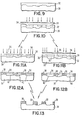
- FIGS. 9-12 depict a method wherein a positive tone etch-resistant latent image is created by: applying a layer of polymeric resist material to a substrate; exposing the layer of-non-metal-containing polymeric resist to radiation capable of crosslinking the polymeric resist in the irradiated area; exposing the layer of polymeric resist material to radiation capable of creating reactive sites at least in the non-crosslinked area of the polymeric resist (FIG. 11 B ) or throughout the polymeric resist material (FIG. 11 A); and preferentially permeating and reacting an organometallic material into the permeable, non-crosslinked area of the resist.
- the etch-resistant latent image created within the resist is dry developed to produce the patterned resist shown in FIG. 13.
- FIGS. 14A-17 show the embodiment of the present invention wherein the polymeric resist material is affected differently by intensity or kind of radiation, and this characteristic is used to obtain image and pattern reversal.
- FIGS. 16A-17 represent the method of obtaining a positive tone image, wherein patterned radiation is applied to the surface of the resist, the dominant reaction is crosslinking in the irradiated areas, and the etch-resistant latent image is created in the areas not exposed to the patterned radiation.
- 14A-15 represent the method of obtaining a negative tone image, wherein the same pattern of radiation but a different kind or intensity of radiation, is applied to the surface of the resist, but the dominant reaction is fragmentation in the irradiated areas, and the etch-resistant latent image is created in the areas exposed to the patterned radiation.
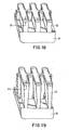
- FIGS. 18 and- 19 depict views of dry developed resist patterns and the type of resist profiles which can be obtained when the change in permeability of the resist material upon irradiation or the permitted permeation by the organometallic reagent is limited to the upper portion of the resist thickness.
- the etch-resistant portion of the polymeric resist is limited to the upper portion of the resist, and either a straight-walled resist structure profile or an undercut resist structure profile (ot tne Kind- shown in FIGS.18 and 19) can be obtained, depending on the oxygen etching conditions used.
- the entire thickness becomes etch-resistant.
- the etched resist profile through the thickness of the resist will depend mostly on the spatial distribution of the radiation intensity through the thickness of the resist layer, and to some extent on the diffusion process.
- Controlled depth of penetration of the organometallic material permits the generation of straight-walled resist structures or undercut wall structures upon dry development, depending on the etch process conditions. Note that in this latter case wherein only the top portion of the resist layer is etch-resistant, it is the process conditions during etching, rather than the radiation profile through the resist thickness, which controls the resist wall profile.
- Selection of the polymer for use in the resist material is based on physical and chemical properties of the polymer such as absorptivity and sensitivity to molecular scission, crosslinking, or other reaction upon exposure to various radiation sources.
- additional polymer properties of interest are thermal stability, ability to form coating solutions, and electrical properties (if the patterned resist is to become part of the electronic device).
- the polymeric resist material must contain a photo active component (PAC) which is sensitive to the radiation source to be used to create the pattern within the resist material.
- PAC photo active component
- Some polymers are sensitive to radiation in themselves and others require the addition of a photo active compound (which is sensitive to the radiation source) to the polymeric material.
- the photo active compound may react with (become covalently linked to) the polymer or may remain in the form of a mixture with the polymer.
- the polymer may or may not contain functional groups capable of reacting with the organometallic material (such as hydroxyl, amine, carboxyl, phenol or imide NH), but polymers containing such functional groups are preferred.
- the polymeric resist material is exposed to a patterned radiation source which either causes increased permeability (via a form of fragmentation or gaseous product generation within the photoactive compound or the polymer itself) or decreased permeability (via crosslinking or other reaction which alters the molecular structure of the resist material, making penetration of the organometallic material more difficult).
- a patterned radiation source which either causes increased permeability (via a form of fragmentation or gaseous product generation within the photoactive compound or the polymer itself) or decreased permeability (via crosslinking or other reaction which alters the molecular structure of the resist material, making penetration of the organometallic material more difficult).
- a patterned radiation source which either causes increased permeability (via a form of fragmentation or gaseous product generation within the photoactive compound or the polymer itself) or decreased permeability (via crosslinking or other reaction which alters the molecular structure of the resist material, making penetration of the organometallic material more difficult).
- permeability is altered uniformly. It is also possible
- An organometallic material is then preferentially permeated into the polymeric resist material to create a patterned latent image which is etch-resistant, enabling subsequent dry development of the resist.
- the ability of the organometallic material to permeate into patterned areas of the polymeric resist material is the result of changes in porosity, polarity (for example, hydrophobicity/hydrophilicity), swelling characteristics of the polymeric resist material, or combinations thereof in the patterned, irradiated area. Whether the final etch-resistant patterned area within the polymeric resist material is a positive tone or negative tone latent image depends upon which factors are more dominant in affecting permeability.
- the degree of permeation/penetration within the more permeable areas of the polymeric resist can be further controlled by process parameters such as length of contact time between the resist material and the organometallic material, contact temperature, and form (gaseous or condensed phase) of the organometallic material.
- FIGS. 1-4 which can be used to illustrate two embodiments of the method of the invention which create a positive tone pattern in the resist:
- a layer of polymeric resist material 12 is applied over the surface of a substrate 10, as shown in F IG . 1.
- the surface of the polymeric resist material 12 is then exposed to patterned radiation in order to reduce permeability in the exposed areas 14, as depicted in FIG. 2.
- the pattern may be created using a mask technique as shown in FIG. 2, or may be created by direct writing of the pattern upon the surface of the resist material.
- the depth of penetration of the radiation into the resist thickness may be partial as shown in FIG. 2, or may be through the entire thickness of the resist material.
- an organometallic material is now applied to the surface of the polymeric resist material 12,14 and allowed to preferentially permeate/diffuse within areas 16 of the resist which have not been reduced in permeability and which are not protected from permeation by areas of reduced permeability 14, as shown in FIG. 3.
- the organometallic material merely diffuses and remains in place.
- the organometallic material reacts with functional groups at sites within the polymeric resist material.
- the areas in which preferential diffusion of the organometallic material has occurred 16 are referred to as an etch-resistant latent image within the resist elsewhere within this disclosure.
- FIG. 4 depicts the positive tone resist pattern created on dry development of the etch-resistant latent image.
- the organometallic material may merely diffuse and remain in place in the more permeable areas; the organometallic material may react with functional groups at sites existing within the polymeric resist, wherein such sites exist throughout the entire polymeric resist material, but reaction occurs only within the permeable areas into which permeation/ penetration can occur.
- the organometallic material may react at sites existing only within the irradiated areas of the polymeric resist, such reactive sites being created via irradiation (the same radiation as that used to create the permeability, or another kind of radiation applied in the same pattern as that used to increase the permeability).
- FIG. 8 depicts the negative tone resist pattern created on.dry development of the etch-resistant latent image.
- FIGS. 9-13 depict an additional preferred embodiment of the present invention in which a positive tone pattern is created within the resist.
- the organometallic material is reacted with irradiation-created sites within the resist.
- the surface of the polymeric resist material 32 is then exposed to patterned radiation in order to reduce permeability in the exposed areas 34, as shown in FIG. 10.
- the polymeric resist material contains no sites capable of the desired reaction with an organometallic material, so such sites are created using radiation.
- the reactive sites must be created in areas which were not initially exposed to radiation (areas other than 34).
- the reactive-site-creating radiation can be applied over the entire surface of the polymeric resist material, as shown in FIG.11 A. This blanket application of radiation may result in creation of the reactive sites 36 throughout the entire polymeric resist material 32, depending on the effect of the initial radiation (applied as shown in FIG. 10) upon the absorption characteristics in the initially irradiated areas. Or, the reactive-site-creating radiation can be selectively applied, as shown in FIG. 11B, in a pattern which is the reverse of the pattern of the initial radiation (applied as shown in FIG. 10). This selective application of the reactive-site-creating radiation results in formation of reactive sites 36 only within the specifically irradiated areas of the polymeric resist material 32.
- the organometallic material is next applied to the surface of the polymeric resist material and allowed to preferentially permeate/diffuse into the permeable areas. Permeability-controlled reaction occurs within particular areas of'the resist 38 as shown in FIG. 12A. Reactive sites exist throughout the polymeric resist material; however, the organometallic material is prevented from reaching reactive sites within the impermeable (or less permeable) areas 34 or areas 40 protected by the impermeable areas 34. Permeability-controlled permeation/penetration of the organometallic material can be even further controlled within particular areas of the resist 38 as shown in FIG. 12B.
- FIG.13 depicts the positive tone pattern obtained on dry development of the etch-resistant latent image 38.
- FIGS. 14A-17 This feature of the present invention is illustrated in FIGS. 14A-17.
- a 'layer of polymeric resist material 50 is applied to the surface of a substrate 54, using methods described previously. Patterned radiation is applied to create areas of increased permeability 52 within the polymeric resist material 50, as depicted in FIG. 14A.
- An organometallic reagent is ' then applied and preferential permeation occurs in the more permeable areas 52.
- the dry developed resist pattern is a negative tone pattern, as shown in FIG. 14B and 15, wherein the etch-resistant areas 52 remain on the substrate 54.
- a crosslinking reagent is . added to the polymeric resist material, the type or intensity of radiation is changed, or a combination of both may be used.
- a polymeric resist material 56 is applied to a substrate 54, by methods previously described. Upon irradiation, the irradiated areas 58, decrease in permeability. An organometallic I reagent is applied and preferential permeation/ diffusion occurs in the more permeable areas 56.
- the dry developed resist pattern is a 'positive tone pattern, as shown in FIG.
- the radiation used to alter the permeability of the resist may penetrate the entire resist thickness, or may only partially penetrate the resist thickness as previously described.
- the ability to alter the profile of the wall structure of the patterned resist depends on a variety of factors, including uniformity of radiation intensity through the resist thickness, the depth of penetration of the radiation into the resist thickness, the depth and degree of permeation by the organometallic material and dry development conditions, as previously described.
- FIGS. 15 and 17 show straight wall structures obtained when the organometallic material permeates the entire resist thickness.
- FIGS. 18 and 19 show .the undercut wall structures which can be obtained when the organometallic material permeates to only a limited depth 64 within the polymeric resist material 62 upon substrate 60.
- the photoactive components ' can be part of the polymer used or can be separate molecules.
- photoactive compounds include (but are not limited to) compounds of the following general structures: (analogues of 5-diazo-Meldrum's acid) where R 1 , R 2 can be H, alkyl, aryl, halogen, alkoxyl, or esterified sulfo groups; R 3 , R 4 represent alkyl, aryl, part of cyclic or heterocyclic groups. Molecules containing two or three of the diazoquinone groups are also included.
- poly(alkene sulfone)s such as poly(butene-1-sulfone) which are used as photoactive compounds in electron-beam resists can act as photoactive compounds in combination with the above-mentioned polymers.
- a positive tone resist pattern was obtained-in the following manner:
- the polymeric resist material was exposed to patterned radiation using a commercially available reflective scan projection tool and "deep" UV exposure (220 to nm). The dosage was varied from about 50 to about 300 mJ/cm". This "deep” UV radiation resulted in an overall crosslinking effect, wherein crosslinking played a more dominant role than the photofragmentation of the diazoquinones in the exposed areas.
- the effect of the crosslinking in the irradiated areas was to reduce the permeability of the irradiated areas to organometallic materials (including the organometallic compound itself and any solvent molecules used as a carrier for the organometallic compound).
- the irradiated resist was treated with an organometallic material comprised of about 5% hexamethylcyclotrisilazane (HMCTS) in o-xylene at about 65°C for a time period which was varied from about 2 minutes to about 15 minutes.
- the preferred temperature and time period depends on the degree of permeation/penetration of the organometallic material desired, and for this polymeric resist material the time period used was about 10 to about 15 minutes.
- organometallic materials of this type which can be used to create etch-resistance in polymeric resists is described in U.S. Patent Application, Serial No. 713,509 1 which is hereby incorporated by reference.
- the organometallic material preferentially permeated/diffused into the non-crosslinked, non-irradiated areas of the polymeric resist, and reacted to silylate the phenolic hydroxy groups of the novolak resin, creating a positive tone etch-resistant latent image within the upper portion of the polymeric resist material.
- the wafer, including resist was rinsed in pure o-xylene for about 10 seconds and then was blown dry using nitrogen.
- the etch-resistant latent image was dry developed using an oxygen plasma in a Temescal parallel plate reactive ion etching tool. Conditions used during etching were about 100 sccm of O 2 at a pressure of about 66,5 ⁇ bar : and a power input of about 500 Watts.
- the patterned resist created included line widths of about 1.25 micrometers at spacings of about 1.25 micrometers. The walls of the resist structure were straight and about 1.8 micrometers in height.
- FIGS. 1-4 illustrate this embodiment of the invention.
- a negative tone resist pattern was created in the following manner:
- the dry-developed resist was a negative tone pattern which included line widths of 1.25 micrometers at line spacings of 1.25 micrometers, wherein the walls of the resist structure were straight and about 1.8 micrometers in height.
- FIGS. 5-8 illustrate this embodiment of the present invention (excluding any additional irradiation for purposes of reducing permeability in areas to prevent organometallic material permeation).
- EXAMPLES 1 and 2 utilized the polymeric resist material directly over a silicon wafer substrate.
- the method of the present invention can be utilized over a substrate of any second polymeric material which has been applied to the surface of the silicon wafer, (or any electronic device substrate).
- second polymeric materials those with high temperature (above 200°C) stability are preferred. Examples include polyimides and hard-baked novolaks. In order to reduce the effort required in removing the resist structure after subsequent processing, a soluble polyimide was used in this example.
- a negative tone resist pattern was obtained using the materials and method steps of EXAMPLE 2, with the following exceptions:
- a preimidized polyimide, a copolymer of 5(6)-amino-1-(4'-aminophenyl)-1,3,3-tri- methylindane isomers with 3,3',3,4'-benzophenone tetracarboxylic dianhydride was used as the second polymeric substrate under the diazoquinone derivative/ novolak polymeric resist material.
- the polyimide was applied to the surface of a silicon wafer from a gamma-butyrolactone solvent using standard spin coating techniques.
- the polyimide layer was dried using an oven bake at about 230°C for a period of about 60 minutes in order to remove the solvent.
- the thickness of the dry polyimide layer was about 3 micrometers.
- the diazoquinone derivative/novolak resist material was applied over the surface of the dried layer of polyimide using techniques previously described. The thickness of the dry layer of resist material was about 2 micrometers.
- the developed pattern included line widths of 1.5 micrometers at line spacings of about 1.5 micrometers.
- the wall structures of the developed resist were slightly tapered as depth into the developed resist increased.
- thickness of the patterned multilayer resist including polyimide underlayer was about 4.8 micrometers.
- a positive tone resist pattern was created as follows: A polymeric resist material comprised of a bisazide photoactive compound, di(p-azidophenyl) sulfide, and a novolak resin synthesized from mixed isomers of cresol and formaldehyde was applied to the surface of a silicon wafer using standard spin coating techniques. The concentration of-photoactive compound was varied between about 12 to about 18 % by weight of the resist material. For purposes of this example, the 18 % concentration of bisazide was preferred. The polymeric resist material was applied using diglyme as the casting solvent, wherein the polymeric resist material comprised: about 30 % by weight of the coating solution. Application of the polymeric resist material to the silicon wafer was followed by an oven bake at about 85°C for a period of about 30 minutes, to remove the diglyme coating solvent. The thickness of the dried resist film was about 0.7 micrometers.
- the polymeric resist film was exposed to patterned radiation using a commercially available reflective scan projection tool and deep UV exposure (220-290 nm).
- the dosage ranged from about 100 to about 200 mJ/cm .
- This deep UV radiation resulted in a dominant crosslinking reaction, wherein the nitrene generated from the photofragmentation of di(p-azidophenyl) sulfide induced the crosslinking reaction.
- the effect of the deep UV radiation was to reduce the permeability of the polymeric resist material in the irradiated areas to organometallic materials (organometallic compounds and solvent carrier molecules).
- FIGS. 1-4 illustrate this embodiment of the invention.
- a positive tone resist pattern was created in the same manner as EXAMPLE 4 using 3,3'-diazidobenzophenone as the photoactive compound in the m-cresol formaldehyde novolak resin.
- the concentration of photoactive compound was about 18 % by weight of the resist material.
- Diglyme was used as the spin coating solvent and the resist material comprised about 30 % by weight of the coating solvent.
- a negative tone resist pattern was created as follows:
- the polymeric resist material was then exposed to radiation using a commercially available refractive step and repeat projection tool and a 405 nm lens.
- the dosage used was about 150 to about 250 mJ/cm .
- the irradiated resist was treated using 5% HMCTS in o-xylene at about 65°C for a period of about 15 minutes, to allow diffusion and reaction of the organometallic material within the polymeric resist material.
- the wafer was rinsed in pure o-xylene for a period of about 10 seconds and then blown dry with nitrogen.
- Dry development of the etch-resistant latent image was achieved using an oxygen plasma in a Temescal reactive ion etching tool. Operational conditions were 6 sccm oxygen flow rate and 6,6 ⁇ bar pressure, at 500 Watts power. Note that low pressure conditions result in a developed resist pattern with a straight wall profile,:whereas higher pressure conditions can be used to obtain an undercut wall profile.
- the developed negative tone patterned resist was comprised of approximately 0.4 micrometer line widths at line spacings of about 0.5 micrometer.
- the wall profiles of the resist structure were somewhat tapered, as described in EXAMPLE 3, and the etch-resistant upper portion of the resist was intentionally undercut via a long 15 minute dry development period.
- the height of the resist wall structure was nearly 2 micrometers, so that an aspect ratio of about 5 was achieved.
- polymeric resist materials which can be utilized in the present invention which contain no functional groups (sites) capable of reacting with the organometallic material until after irradiation.
- examples of such polymeric resist materials include the p-t-butoxycarbonyloxystyrene containing triphenyl-sulfonium hexafluorarsenate which is described in U.S. Patent No. 4 552 833 and previously incorporated by reference herein.
- photo-fries rearrangement materials of the type described in U.S. Patent Application, Serial No. 679 527 and previously incorporated by reference herein.
Landscapes
- Chemical & Material Sciences (AREA)
- Chemical Kinetics & Catalysis (AREA)
- Inorganic Chemistry (AREA)
- Organic Chemistry (AREA)
- Physics & Mathematics (AREA)
- General Physics & Mathematics (AREA)
- Exposure And Positioning Against Photoresist Photosensitive Materials (AREA)
- Photosensitive Polymer And Photoresist Processing (AREA)
- Materials For Photolithography (AREA)
- Drying Of Semiconductors (AREA)
Applications Claiming Priority (2)
| Application Number | Priority Date | Filing Date | Title |
|---|---|---|---|
| US06/741,779 US4613398A (en) | 1985-06-06 | 1985-06-06 | Formation of etch-resistant resists through preferential permeation |
| US741779 | 1985-06-06 |
Publications (3)
| Publication Number | Publication Date |
|---|---|
| EP0204253A2 true EP0204253A2 (de) | 1986-12-10 |
| EP0204253A3 EP0204253A3 (en) | 1988-07-27 |
| EP0204253B1 EP0204253B1 (de) | 1993-10-20 |
Family
ID=24982156
Family Applications (1)
| Application Number | Title | Priority Date | Filing Date |
|---|---|---|---|
| EP86107186A Expired - Lifetime EP0204253B1 (de) | 1985-06-06 | 1986-05-27 | Verfahren zur Herstellung von ätzresistenten Schutzlacken durch bevorzugtes Eindringen |
Country Status (5)
| Country | Link |
|---|---|
| US (1) | US4613398A (de) |
| EP (1) | EP0204253B1 (de) |
| JP (1) | JPS61284924A (de) |
| CA (1) | CA1251680A (de) |
| DE (1) | DE3689179T2 (de) |
Cited By (13)
| Publication number | Priority date | Publication date | Assignee | Title |
|---|---|---|---|---|
| EP0248779A1 (de) * | 1986-05-08 | 1987-12-09 | U C B, S.A. | Verfahren zur Herstellung von positiven Schutzlackbildern |
| EP0250762A2 (de) * | 1986-06-23 | 1988-01-07 | International Business Machines Corporation | Herstellung von permeabelen polymeren Filmen oder Schichten durch Auslaugung |
| EP0281182A1 (de) * | 1987-02-20 | 1988-09-07 | Koninklijke Philips Electronics N.V. | Verfahren zur Herstellung von Halbleitervorrichtungen |
| EP0318956A2 (de) * | 1987-11-30 | 1989-06-07 | Fujitsu Limited | Positiv arbeitende Photoresistzusammensetzung und Verfahren zur Herstellung von positiven Reliefbildern |
| EP0352739A2 (de) * | 1988-07-29 | 1990-01-31 | Shipley Company Inc. | Verfahren zur Herstellung von Fotolackstrukturen unter Verwendung eines chemisch verstärkten und metallisierten Materials |
| GB2221767A (en) * | 1988-08-09 | 1990-02-14 | Plessey Co Plc | Bi-level resist etch process |
| EP0410268A2 (de) * | 1989-07-27 | 1991-01-30 | International Business Machines Corporation | Schutzlackerzeugungsverfahren durch Grenzflächensilylierung |
| EP0425411A2 (de) * | 1989-10-23 | 1991-05-02 | International Business Machines Corporation | Mit Trockenverfahren entwickelbarer hochempfindlicher Photoresist für das tiefe UV |
| EP0515212A1 (de) * | 1991-05-24 | 1992-11-25 | Nippon Paint Co., Ltd. | Verfahren zur Herstellung eines Resistmusters |
| EP0525721A1 (de) * | 1991-07-31 | 1993-02-03 | Texas Instruments Incorporated | Hochauflösendes lithographisches Verfahren |
| EP0543762A1 (de) * | 1991-11-22 | 1993-05-26 | International Business Machines Corporation | Mit Trockenverfahren entwickelbare Photoresistzusammensetzungen und Verfahren zur Verwendung |
| US5229258A (en) * | 1990-04-12 | 1993-07-20 | Siemens Aktiengesellschaft | Method for producing a resist structure |
| US5733706A (en) * | 1994-05-25 | 1998-03-31 | Siemens Aktiengesellschaft | Dry-developable positive resist |
Families Citing this family (89)
| Publication number | Priority date | Publication date | Assignee | Title |
|---|---|---|---|---|
| US5215867A (en) * | 1983-09-16 | 1993-06-01 | At&T Bell Laboratories | Method with gas functionalized plasma developed layer |
| US4810601A (en) * | 1984-12-07 | 1989-03-07 | International Business Machines Corporation | Top imaged resists |
| GB2170015A (en) * | 1985-01-11 | 1986-07-23 | Philips Electronic Associated | Method of manufacturing a semiconductor device |
| US5264319A (en) * | 1985-05-10 | 1993-11-23 | Hitachi, Ltd. | Photosensitive resin composition having high resistance to oxygen plasma, containing alkali-soluble organosilicon polymer and photosensitive dissolution inhibitor |
| US4751170A (en) * | 1985-07-26 | 1988-06-14 | Nippon Telegraph And Telephone Corporation | Silylation method onto surface of polymer membrane and pattern formation process by the utilization of silylation method |
| US4657845A (en) * | 1986-01-14 | 1987-04-14 | International Business Machines Corporation | Positive tone oxygen plasma developable photoresist |
| EP0238690B1 (de) * | 1986-03-27 | 1991-11-06 | International Business Machines Corporation | Verfahren zur Herstellung von Seitenstrukturen |
| US4908094A (en) * | 1986-04-14 | 1990-03-13 | International Business Machines Corporation | Method for laminating organic materials via surface modification |
| US4715941A (en) * | 1986-04-14 | 1987-12-29 | International Business Machines Corporation | Surface modification of organic materials to improve adhesion |
| US4737425A (en) * | 1986-06-10 | 1988-04-12 | International Business Machines Corporation | Patterned resist and process |
| EP0249457B1 (de) * | 1986-06-12 | 1991-08-21 | Matsushita Electric Industrial Co., Ltd. | Bilderzeugungsverfahren |
| US4816112A (en) * | 1986-10-27 | 1989-03-28 | International Business Machines Corporation | Planarization process through silylation |
| US4867838A (en) * | 1986-10-27 | 1989-09-19 | International Business Machines Corporation | Planarization through silylation |
| US4931351A (en) * | 1987-01-12 | 1990-06-05 | Eastman Kodak Company | Bilayer lithographic process |
| JPH07113774B2 (ja) * | 1987-05-29 | 1995-12-06 | 株式会社日立製作所 | パタ−ンの形成方法 |
| JPH01243430A (ja) * | 1988-03-25 | 1989-09-28 | Nec Corp | モリブデンシリサイドのエッチング方法 |
| US5108875A (en) * | 1988-07-29 | 1992-04-28 | Shipley Company Inc. | Photoresist pattern fabrication employing chemically amplified metalized material |
| US5407786A (en) * | 1988-08-09 | 1995-04-18 | Kabushiki Kaisha Toshiba | Method of forming a mask on a semiconductor substrate via photosensitive resin deposition, ammonia treatment and selective silylation |
| US5079131A (en) * | 1988-08-29 | 1992-01-07 | Shipley Company Inc. | Method of forming positive images through organometallic treatment of negative acid hardening cross-linked photoresist formulations |
| US5094936A (en) * | 1988-09-16 | 1992-03-10 | Texas Instruments Incorporated | High pressure photoresist silylation process and apparatus |
| US6051659A (en) * | 1992-08-20 | 2000-04-18 | International Business Machines Corporation | Highly sensitive positive photoresist composition |
| JPH02151865A (ja) * | 1988-11-22 | 1990-06-11 | Ucb Sa | 高温反応処理方法 |
| US5356758A (en) * | 1988-12-28 | 1994-10-18 | Texas Instruments Incorporated | Method and apparatus for positively patterning a surface-sensitive resist on a semiconductor wafer |
| JP3001607B2 (ja) * | 1989-04-24 | 2000-01-24 | シーメンス、アクチエンゲゼルシヤフト | 二層法における寸法安定な構造転写方法 |
| US5275920A (en) * | 1989-04-24 | 1994-01-04 | Siemens Aktiengesellschaft | Method of dry development utilizing quinone diazide and basic polymer resist with latent image intensification through treatment with silicon-organic compound in water |
| DE3913434A1 (de) * | 1989-04-24 | 1990-10-25 | Siemens Ag | Trockenwickelbares resistsystem |
| US5053318A (en) * | 1989-05-18 | 1991-10-01 | Shipley Company Inc. | Plasma processing with metal mask integration |
| US5213917A (en) * | 1989-05-18 | 1993-05-25 | Shipley Company Inc. | Plasma processing with metal mask integration |
| US5217851A (en) * | 1989-09-05 | 1993-06-08 | Mitsubishi Denki Kabushiki Kaisha | Pattern forming method capable of providing an excellent pattern of high resolution power and high sensitivity |
| GB8920622D0 (en) * | 1989-09-12 | 1989-10-25 | Du Pont | Improvements in or relating to lithographic printing plates |
| US4968552A (en) * | 1989-10-13 | 1990-11-06 | International Business Machines Corp. | Versatile reactive ion etch barriers from polyamic acid salts |
| US5139925A (en) * | 1989-10-18 | 1992-08-18 | Massachusetts Institute Of Technology | Surface barrier silylation of novolak film without photoactive additive patterned with 193 nm excimer laser |
| US5362606A (en) * | 1989-10-18 | 1994-11-08 | Massachusetts Institute Of Technology | Positive resist pattern formation through focused ion beam exposure and surface barrier silylation |
| JP2769038B2 (ja) * | 1990-03-19 | 1998-06-25 | 三菱電機株式会社 | パターン形成方法 |
| US5061604A (en) * | 1990-05-04 | 1991-10-29 | Minnesota Mining And Manufacturing Company | Negative crystalline photoresists for UV photoimaging |
| US5275913A (en) * | 1990-05-08 | 1994-01-04 | Industrial Technology Research Institute | Method for preparing resist patterns utilizing solvent development with subsequent resist pattern transfer, via a photo-hardening liquid adhesive, to a receiver substrate and oxygen reactive ion etching |
| JP2603148B2 (ja) * | 1990-06-08 | 1997-04-23 | 三菱電機株式会社 | パターン形成方法 |
| US5059500A (en) * | 1990-10-10 | 1991-10-22 | Polaroid Corporation | Process for forming a color filter |
| US5140396A (en) * | 1990-10-10 | 1992-08-18 | Polaroid Corporation | Filter and solid state imager incorporating this filter |
| EP0492256B1 (de) * | 1990-12-20 | 1996-08-14 | Siemens Aktiengesellschaft | Photolithographische Strukturerzeugung |
| US5112434A (en) * | 1991-03-20 | 1992-05-12 | Shipley Company Inc. | Method for patterning electroless metal on a substrate followed by reactive ion etching |
| US5322764A (en) * | 1991-05-21 | 1994-06-21 | Mitsubishi Denki Kabushiki Kaisha | Method for forming a patterned resist |
| US5320934A (en) * | 1991-06-28 | 1994-06-14 | Misium George R | Bilayer photolithographic process |
| US5304453A (en) * | 1991-07-11 | 1994-04-19 | Industrial Technology Research Institute | Method for preparing resist patterns through image layer transfer to a receiver substrate, via a photo-hardening organic liquid adhesive, with subsequent oxygen reactive ion etching |
| US5250395A (en) * | 1991-07-25 | 1993-10-05 | International Business Machines Corporation | Process for imaging of photoresist including treatment of the photoresist with an organometallic compound |
| US5229256A (en) * | 1991-12-06 | 1993-07-20 | International Business Machines Corporation | Process for generating positive-tone photoresist image |
| JP2559192B2 (ja) * | 1992-04-07 | 1996-12-04 | インターナショナル・ビジネス・マシーンズ・コーポレイション | ヒドロキシ芳香族化合物の炭酸化物を生成させるための改良された方法 |
| KR960012630B1 (ko) * | 1993-08-23 | 1996-09-23 | 현대전자산업 주식회사 | 반도체소자의 미세패턴 형성방법 |
| GB2284300B (en) * | 1993-11-10 | 1997-11-19 | Hyundai Electronics Ind | Process for forming fine pattern of semiconductor device |
| WO1995032237A1 (en) * | 1994-05-19 | 1995-11-30 | Minnesota Mining And Manufacturing Company | Polymeric article having improved hydrophilicity and a method of making the same |
| KR0174316B1 (ko) * | 1994-07-05 | 1999-04-01 | 모리시다 요이치 | 미세패턴 형성방법 |
| WO1996015861A1 (en) * | 1994-11-22 | 1996-05-30 | Complex Fluid Systems, Inc. | Non-aminic photoresist adhesion promoters for microelectronic applications |
| US5871871A (en) * | 1996-09-20 | 1999-02-16 | International Business Machines Corporation | Stabilized multi-layered structure of color filters on a silicon chip and a method for making |
| US6187515B1 (en) * | 1998-05-07 | 2001-02-13 | Trw Inc. | Optical integrated circuit microbench system |
| US6610602B2 (en) | 1999-06-29 | 2003-08-26 | The Research Foundation Of State University Of New York | Magnetic field sensor and method of manufacturing same using a self-organizing polymer mask |
| AU7124100A (en) | 1999-09-10 | 2001-04-10 | Unaxis Usa Inc. | Magnetic pole fabrication process and device |
| US6547975B1 (en) | 1999-10-29 | 2003-04-15 | Unaxis Usa Inc. | Magnetic pole fabrication process and device |
| KR100669752B1 (ko) * | 2004-11-10 | 2007-01-16 | 삼성에스디아이 주식회사 | 유기 박막 트랜지스터, 이의 제조 방법 및 이를 구비한평판표시장치 |
| WO2008007550A1 (fr) * | 2006-07-14 | 2008-01-17 | Konica Minolta Holdings, Inc. | Procédé de fabrication de plaque d'impression lithographique |
| KR20090125078A (ko) * | 2007-01-31 | 2009-12-03 | 뉴사우스 이노베이션즈 피티와이 리미티드 | 선택된 물질에 개구부들을 형성하는 방법 |
| US20090170992A1 (en) * | 2007-12-28 | 2009-07-02 | Saint-Gobain Performance Plastics Corporation | Etch resistant polymer composition |
| DK3030682T3 (da) | 2013-08-05 | 2020-09-14 | Twist Bioscience Corp | De novo synthesized gene libraries |
| WO2016126987A1 (en) | 2015-02-04 | 2016-08-11 | Twist Bioscience Corporation | Compositions and methods for synthetic gene assembly |
| US10669304B2 (en) | 2015-02-04 | 2020-06-02 | Twist Bioscience Corporation | Methods and devices for de novo oligonucleic acid assembly |
| WO2016172377A1 (en) | 2015-04-21 | 2016-10-27 | Twist Bioscience Corporation | Devices and methods for oligonucleic acid library synthesis |
| US20180224741A1 (en) * | 2015-08-06 | 2018-08-09 | Rohm And Haas Electronic Materials Llc | Compositions and methods for forming a pixel-defining layer |
| CA2998169A1 (en) | 2015-09-18 | 2017-03-23 | Twist Bioscience Corporation | Oligonucleic acid variant libraries and synthesis thereof |
| CN108698012A (zh) | 2015-09-22 | 2018-10-23 | 特韦斯特生物科学公司 | 用于核酸合成的柔性基底 |
| US10695794B2 (en) | 2015-10-09 | 2020-06-30 | Asm Ip Holding B.V. | Vapor phase deposition of organic films |
| WO2017095958A1 (en) | 2015-12-01 | 2017-06-08 | Twist Bioscience Corporation | Functionalized surfaces and preparation thereof |
| US10453701B2 (en) | 2016-06-01 | 2019-10-22 | Asm Ip Holding B.V. | Deposition of organic films |
| SG11201901563UA (en) | 2016-08-22 | 2019-03-28 | Twist Bioscience Corp | De novo synthesized nucleic acid libraries |
| JP6871364B2 (ja) | 2016-09-21 | 2021-05-12 | ツイスト バイオサイエンス コーポレーション | 核酸に基づくデータ保存 |
| US10907274B2 (en) | 2016-12-16 | 2021-02-02 | Twist Bioscience Corporation | Variant libraries of the immunological synapse and synthesis thereof |
| EP3586255A4 (de) | 2017-02-22 | 2021-03-31 | Twist Bioscience Corporation | Nukleinsäurebasierte datenspeicherung |
| US10894959B2 (en) | 2017-03-15 | 2021-01-19 | Twist Bioscience Corporation | Variant libraries of the immunological synapse and synthesis thereof |
| JP7169999B2 (ja) | 2017-06-12 | 2022-11-11 | ツイスト バイオサイエンス コーポレーション | シームレス核酸アセンブリのための方法 |
| WO2018231864A1 (en) | 2017-06-12 | 2018-12-20 | Twist Bioscience Corporation | Methods for seamless nucleic acid assembly |
| KR20200047706A (ko) | 2017-09-11 | 2020-05-07 | 트위스트 바이오사이언스 코포레이션 | Gpcr 결합 단백질 및 이의 합성 방법 |
| JP6814116B2 (ja) * | 2017-09-13 | 2021-01-13 | キオクシア株式会社 | 半導体装置の製造方法および半導体製造装置 |
| JP7066840B2 (ja) | 2017-10-20 | 2022-05-13 | ツイスト バイオサイエンス コーポレーション | ポリヌクレオチド合成のための加熱されたナノウェル |
| CA3088911A1 (en) | 2018-01-04 | 2019-07-11 | Twist Bioscience Corporation | Dna-based storage device and method for synthesizing polynucleotides using the device |
| CA3100739A1 (en) | 2018-05-18 | 2019-11-21 | Twist Bioscience Corporation | Polynucleotides, reagents, and methods for nucleic acid hybridization |
| EP3938506A4 (de) | 2019-02-26 | 2022-12-14 | Twist Bioscience Corporation | Variante nukleinsäurebibliotheken zur optimierung von antikörpern |
| CN113766930A (zh) | 2019-02-26 | 2021-12-07 | 特韦斯特生物科学公司 | Glp1受体的变异核酸文库 |
| JP7163221B2 (ja) * | 2019-03-11 | 2022-10-31 | キオクシア株式会社 | 高分子材料、組成物および半導体装置の製造方法 |
| US11332738B2 (en) | 2019-06-21 | 2022-05-17 | Twist Bioscience Corporation | Barcode-based nucleic acid sequence assembly |
| EP4034566A4 (de) | 2019-09-23 | 2024-01-24 | Twist Bioscience Corporation | Variante nukleinsäurebibliotheken für crth2 |
| JP2022142897A (ja) | 2021-03-17 | 2022-10-03 | キオクシア株式会社 | パターン形成方法及び半導体装置の製造方法 |
Citations (6)
| Publication number | Priority date | Publication date | Assignee | Title |
|---|---|---|---|---|
| US4357369A (en) | 1981-11-10 | 1982-11-02 | Rca Corporation | Method of plasma etching a substrate |
| US4396704A (en) | 1981-04-22 | 1983-08-02 | Bell Telephone Laboratories, Incorporated | Solid state devices produced by organometallic plasma developed resists |
| US4426247A (en) | 1982-04-12 | 1984-01-17 | Nippon Telegraph & Telephone Public Corporation | Method for forming micropattern |
| US4430153A (en) | 1983-06-30 | 1984-02-07 | International Business Machines Corporation | Method of forming an RIE etch barrier by in situ conversion of a silicon containing alkyl polyamide/polyimide |
| US4433044A (en) | 1982-11-15 | 1984-02-21 | Rca Corporation | Dry developable positive photoresists |
| US4552833A (en) | 1984-05-14 | 1985-11-12 | International Business Machines Corporation | Radiation sensitive and oxygen plasma developable resist |
Family Cites Families (6)
| Publication number | Priority date | Publication date | Assignee | Title |
|---|---|---|---|---|
| US4460436A (en) * | 1983-09-06 | 1984-07-17 | International Business Machines Corporation | Deposition of polymer films by means of ion beams |
| CA1248402A (en) * | 1983-09-16 | 1989-01-10 | Larry E. Stillwagon | Method of making articles using gas functionalized plasma developed layer |
| GB8403698D0 (en) * | 1984-02-13 | 1984-03-14 | British Telecomm | Semiconductor device fabrication |
| GB8427149D0 (en) * | 1984-10-26 | 1984-12-05 | Ucb Sa | Resist materials |
| CA1267378A (en) * | 1984-12-07 | 1990-04-03 | Jer-Ming Yang | Top imaged and organosilicon treated polymer layer developable with plasma |
| JPS61268028A (ja) * | 1985-04-08 | 1986-11-27 | インタ−ナショナル ビジネス マシ−ンズ コ−ポレ−ション | ホトレジスト中にマスク像を現像する方法 |
-
1985
- 1985-06-06 US US06/741,779 patent/US4613398A/en not_active Expired - Lifetime
- 1985-11-19 CA CA000495659A patent/CA1251680A/en not_active Expired
-
1986
- 1986-04-18 JP JP61088401A patent/JPS61284924A/ja active Pending
- 1986-05-27 EP EP86107186A patent/EP0204253B1/de not_active Expired - Lifetime
- 1986-05-27 DE DE86107186T patent/DE3689179T2/de not_active Expired - Fee Related
Patent Citations (6)
| Publication number | Priority date | Publication date | Assignee | Title |
|---|---|---|---|---|
| US4396704A (en) | 1981-04-22 | 1983-08-02 | Bell Telephone Laboratories, Incorporated | Solid state devices produced by organometallic plasma developed resists |
| US4357369A (en) | 1981-11-10 | 1982-11-02 | Rca Corporation | Method of plasma etching a substrate |
| US4426247A (en) | 1982-04-12 | 1984-01-17 | Nippon Telegraph & Telephone Public Corporation | Method for forming micropattern |
| US4433044A (en) | 1982-11-15 | 1984-02-21 | Rca Corporation | Dry developable positive photoresists |
| US4430153A (en) | 1983-06-30 | 1984-02-07 | International Business Machines Corporation | Method of forming an RIE etch barrier by in situ conversion of a silicon containing alkyl polyamide/polyimide |
| US4552833A (en) | 1984-05-14 | 1985-11-12 | International Business Machines Corporation | Radiation sensitive and oxygen plasma developable resist |
Non-Patent Citations (3)
| Title |
|---|
| J. ELECTROCHEM. SOC., vol. 131, no. 7, July 1984 (1984-07-01), pages 1658 - 64 |
| J. ELECTROCHEM. SOC., vol. 131, no. 7, July 1984 (1984-07-01), pages 1664 - 70 |
| SOLID STATE TECHNOLOGY, vol. 27, no. 2, February 1984 (1984-02-01), pages 145 - 55 |
Cited By (20)
| Publication number | Priority date | Publication date | Assignee | Title |
|---|---|---|---|---|
| EP0248779A1 (de) * | 1986-05-08 | 1987-12-09 | U C B, S.A. | Verfahren zur Herstellung von positiven Schutzlackbildern |
| EP0250762A2 (de) * | 1986-06-23 | 1988-01-07 | International Business Machines Corporation | Herstellung von permeabelen polymeren Filmen oder Schichten durch Auslaugung |
| EP0250762B1 (de) * | 1986-06-23 | 1995-03-08 | International Business Machines Corporation | Herstellung von permeabelen polymeren Filmen oder Schichten durch Auslaugung |
| EP0281182A1 (de) * | 1987-02-20 | 1988-09-07 | Koninklijke Philips Electronics N.V. | Verfahren zur Herstellung von Halbleitervorrichtungen |
| EP0318956A2 (de) * | 1987-11-30 | 1989-06-07 | Fujitsu Limited | Positiv arbeitende Photoresistzusammensetzung und Verfahren zur Herstellung von positiven Reliefbildern |
| EP0318956A3 (de) * | 1987-11-30 | 1990-09-12 | Fujitsu Limited | Positiv arbeitende Photoresistzusammensetzung und Verfahren zur Herstellung von positiven Reliefbildern |
| EP0352739A3 (de) * | 1988-07-29 | 1991-09-11 | Shipley Company Inc. | Verfahren zur Herstellung von Fotolackstrukturen unter Verwendung eines chemisch verstärkten und metallisierten Materials |
| EP0352739A2 (de) * | 1988-07-29 | 1990-01-31 | Shipley Company Inc. | Verfahren zur Herstellung von Fotolackstrukturen unter Verwendung eines chemisch verstärkten und metallisierten Materials |
| GB2221767A (en) * | 1988-08-09 | 1990-02-14 | Plessey Co Plc | Bi-level resist etch process |
| EP0410268A3 (en) * | 1989-07-27 | 1991-10-09 | International Business Machines Corporation | Etch resistant pattern formation via interfacial silylation process |
| EP0410268A2 (de) * | 1989-07-27 | 1991-01-30 | International Business Machines Corporation | Schutzlackerzeugungsverfahren durch Grenzflächensilylierung |
| EP0425411A2 (de) * | 1989-10-23 | 1991-05-02 | International Business Machines Corporation | Mit Trockenverfahren entwickelbarer hochempfindlicher Photoresist für das tiefe UV |
| EP0425411A3 (en) * | 1989-10-23 | 1992-01-08 | International Business Machines Corporation | Highly sensitive dry developable deep uv photoresist |
| US5229258A (en) * | 1990-04-12 | 1993-07-20 | Siemens Aktiengesellschaft | Method for producing a resist structure |
| EP0515212A1 (de) * | 1991-05-24 | 1992-11-25 | Nippon Paint Co., Ltd. | Verfahren zur Herstellung eines Resistmusters |
| EP0525721A1 (de) * | 1991-07-31 | 1993-02-03 | Texas Instruments Incorporated | Hochauflösendes lithographisches Verfahren |
| US5387497A (en) * | 1991-07-31 | 1995-02-07 | Texas Instruments Incorporated | High resolution lithography method using hydrogen developing reagent |
| EP0543762A1 (de) * | 1991-11-22 | 1993-05-26 | International Business Machines Corporation | Mit Trockenverfahren entwickelbare Photoresistzusammensetzungen und Verfahren zur Verwendung |
| US5322765A (en) * | 1991-11-22 | 1994-06-21 | International Business Machines Corporation | Dry developable photoresist compositions and method for use thereof |
| US5733706A (en) * | 1994-05-25 | 1998-03-31 | Siemens Aktiengesellschaft | Dry-developable positive resist |
Also Published As
| Publication number | Publication date |
|---|---|
| DE3689179T2 (de) | 1994-05-05 |
| EP0204253A3 (en) | 1988-07-27 |
| CA1251680A (en) | 1989-03-28 |
| US4613398A (en) | 1986-09-23 |
| DE3689179D1 (de) | 1993-11-25 |
| EP0204253B1 (de) | 1993-10-20 |
| JPS61284924A (ja) | 1986-12-15 |
Similar Documents
| Publication | Publication Date | Title |
|---|---|---|
| US4613398A (en) | Formation of etch-resistant resists through preferential permeation | |
| US6709807B2 (en) | Process for reducing edge roughness in patterned photoresist | |
| US6319655B1 (en) | Modification of 193 nm sensitive photoresist materials by electron beam exposure | |
| JP3010678B2 (ja) | 金属マスク集積によるプラズマ処理方法 | |
| JP3290194B2 (ja) | フォトレジスト | |
| JPH05232707A (ja) | 乾式現像可能なフォトレジスト組成物およびその使用方法 | |
| US6730458B1 (en) | Method for forming fine patterns through effective glass transition temperature reduction | |
| US6258514B1 (en) | Top surface imaging technique using a topcoat delivery system | |
| US6340556B1 (en) | Tailoring of linewidth through electron beam post exposure | |
| US5266424A (en) | Method of forming pattern and method of manufacturing photomask using such method | |
| JPH10301286A (ja) | 化学的に増幅されたレジスト | |
| US5262283A (en) | Method for producing a resist structure | |
| US5229258A (en) | Method for producing a resist structure | |
| JP2954274B2 (ja) | 乾式現像可能のレジスト系 | |
| EP0186798B1 (de) | Plasmaentwickelfähige Schutzlacke mit Oberflächenbild | |
| JP2000100700A (ja) | パターン形成方法およびハイブリッド露光方法 | |
| EP0244572B1 (de) | Zwei-Schichten-Photolack-Verfahren mit Deckschicht | |
| JPH05507154A (ja) | 酸触媒レジスト用保護膜 | |
| JPS61294433A (ja) | 高解像度感光性樹脂組成物およびこれを使用するサブミクロンパタ−ンの製造方法 | |
| JPH0462661B2 (de) | ||
| US5213917A (en) | Plasma processing with metal mask integration | |
| Koibuchi et al. | A Series Of Azide-Phenolic Resin Resists For The Range Of Deep UV To Visible Light | |
| US6989227B2 (en) | E-beam curable resist and process for e-beam curing the resist | |
| EP0622683A1 (de) | Resiststrukturen mit durchgehenden Löchern, die ein bestimmtes Profil aufweisen, sowie Verfahren zu deren Herstellung | |
| JPS58214149A (ja) | 微細パタ−ン形成方法 |
Legal Events
| Date | Code | Title | Description |
|---|---|---|---|
| PUAI | Public reference made under article 153(3) epc to a published international application that has entered the european phase |
Free format text: ORIGINAL CODE: 0009012 |
|
| AK | Designated contracting states |
Kind code of ref document: A2 Designated state(s): DE FR GB IT |
|
| 17P | Request for examination filed |
Effective date: 19870422 |
|
| PUAL | Search report despatched |
Free format text: ORIGINAL CODE: 0009013 |
|
| AK | Designated contracting states |
Kind code of ref document: A3 Designated state(s): DE FR GB IT |
|
| 17Q | First examination report despatched |
Effective date: 19881020 |
|
| GRAA | (expected) grant |
Free format text: ORIGINAL CODE: 0009210 |
|
| AK | Designated contracting states |
Kind code of ref document: B1 Designated state(s): DE FR GB IT |
|
| PG25 | Lapsed in a contracting state [announced via postgrant information from national office to epo] |
Ref country code: IT Free format text: LAPSE BECAUSE OF FAILURE TO SUBMIT A TRANSLATION OF THE DESCRIPTION OR TO PAY THE FEE WITHIN THE PRESCRIBED TIME-LIMIT;WARNING: LAPSES OF ITALIAN PATENTS WITH EFFECTIVE DATE BEFORE 2007 MAY HAVE OCCURRED AT ANY TIME BEFORE 2007. THE CORRECT EFFECTIVE DATE MAY BE DIFFERENT FROM THE ONE RECORDED. Effective date: 19931020 |
|
| REF | Corresponds to: |
Ref document number: 3689179 Country of ref document: DE Date of ref document: 19931125 |
|
| ET | Fr: translation filed | ||
| PLBE | No opposition filed within time limit |
Free format text: ORIGINAL CODE: 0009261 |
|
| STAA | Information on the status of an ep patent application or granted ep patent |
Free format text: STATUS: NO OPPOSITION FILED WITHIN TIME LIMIT |
|
| 26N | No opposition filed | ||
| PGFP | Annual fee paid to national office [announced via postgrant information from national office to epo] |
Ref country code: GB Payment date: 19960422 Year of fee payment: 11 |
|
| PGFP | Annual fee paid to national office [announced via postgrant information from national office to epo] |
Ref country code: FR Payment date: 19960507 Year of fee payment: 11 |
|
| PGFP | Annual fee paid to national office [announced via postgrant information from national office to epo] |
Ref country code: DE Payment date: 19960529 Year of fee payment: 11 |
|
| PG25 | Lapsed in a contracting state [announced via postgrant information from national office to epo] |
Ref country code: GB Effective date: 19970527 |
|
| GBPC | Gb: european patent ceased through non-payment of renewal fee |
Effective date: 19970527 |
|
| PG25 | Lapsed in a contracting state [announced via postgrant information from national office to epo] |
Ref country code: FR Free format text: LAPSE BECAUSE OF NON-PAYMENT OF DUE FEES Effective date: 19980130 |
|
| PG25 | Lapsed in a contracting state [announced via postgrant information from national office to epo] |
Ref country code: DE Free format text: LAPSE BECAUSE OF NON-PAYMENT OF DUE FEES Effective date: 19980203 |
|
| REG | Reference to a national code |
Ref country code: FR Ref legal event code: ST |