EP0196231B1 - Developing apparatus - Google Patents
Developing apparatus Download PDFInfo
- Publication number
- EP0196231B1 EP0196231B1 EP86302265A EP86302265A EP0196231B1 EP 0196231 B1 EP0196231 B1 EP 0196231B1 EP 86302265 A EP86302265 A EP 86302265A EP 86302265 A EP86302265 A EP 86302265A EP 0196231 B1 EP0196231 B1 EP 0196231B1
- Authority
- EP
- European Patent Office
- Prior art keywords
- developing agent
- toner
- developing apparatus
- carrier
- movable
- Prior art date
- Legal status (The legal status is an assumption and is not a legal conclusion. Google has not performed a legal analysis and makes no representation as to the accuracy of the status listed.)
- Expired
Links
Images


Classifications
-
- G—PHYSICS
- G03—PHOTOGRAPHY; CINEMATOGRAPHY; ANALOGOUS TECHNIQUES USING WAVES OTHER THAN OPTICAL WAVES; ELECTROGRAPHY; HOLOGRAPHY
- G03G—ELECTROGRAPHY; ELECTROPHOTOGRAPHY; MAGNETOGRAPHY
- G03G15/00—Apparatus for electrographic processes using a charge pattern
- G03G15/06—Apparatus for electrographic processes using a charge pattern for developing
- G03G15/08—Apparatus for electrographic processes using a charge pattern for developing using a solid developer, e.g. powder developer
- G03G15/0806—Apparatus for electrographic processes using a charge pattern for developing using a solid developer, e.g. powder developer on a donor element, e.g. belt, roller
- G03G15/0812—Apparatus for electrographic processes using a charge pattern for developing using a solid developer, e.g. powder developer on a donor element, e.g. belt, roller characterised by the developer regulating means, e.g. structure of doctor blade
-
- G—PHYSICS
- G03—PHOTOGRAPHY; CINEMATOGRAPHY; ANALOGOUS TECHNIQUES USING WAVES OTHER THAN OPTICAL WAVES; ELECTROGRAPHY; HOLOGRAPHY
- G03G—ELECTROGRAPHY; ELECTROPHOTOGRAPHY; MAGNETOGRAPHY
- G03G15/00—Apparatus for electrographic processes using a charge pattern
- G03G15/06—Apparatus for electrographic processes using a charge pattern for developing
- G03G15/08—Apparatus for electrographic processes using a charge pattern for developing using a solid developer, e.g. powder developer
- G03G15/0806—Apparatus for electrographic processes using a charge pattern for developing using a solid developer, e.g. powder developer on a donor element, e.g. belt, roller
- G03G15/0808—Apparatus for electrographic processes using a charge pattern for developing using a solid developer, e.g. powder developer on a donor element, e.g. belt, roller characterised by the developer supplying means, e.g. structure of developer supply roller
-
- G—PHYSICS
- G03—PHOTOGRAPHY; CINEMATOGRAPHY; ANALOGOUS TECHNIQUES USING WAVES OTHER THAN OPTICAL WAVES; ELECTROGRAPHY; HOLOGRAPHY
- G03G—ELECTROGRAPHY; ELECTROPHOTOGRAPHY; MAGNETOGRAPHY
- G03G2215/00—Apparatus for electrophotographic processes
- G03G2215/06—Developing structures, details
- G03G2215/0602—Developer
- G03G2215/0604—Developer solid type
- G03G2215/0614—Developer solid type one-component
-
- G—PHYSICS
- G03—PHOTOGRAPHY; CINEMATOGRAPHY; ANALOGOUS TECHNIQUES USING WAVES OTHER THAN OPTICAL WAVES; ELECTROGRAPHY; HOLOGRAPHY
- G03G—ELECTROGRAPHY; ELECTROPHOTOGRAPHY; MAGNETOGRAPHY
- G03G2215/00—Apparatus for electrophotographic processes
- G03G2215/06—Developing structures, details
- G03G2215/0634—Developing device
- G03G2215/0636—Specific type of dry developer device
Definitions
- This invention relates to a developing apparatus, and more particularly relates to improvements in and concerning a developing apparatus to be used in an electrophotographic system or an electrographic system for converting an electrostatic image formed on a photosensitive material or a dielectric material into a visible image with a one component developing agent formed solely of a non-magnetic toner.
- the developing apparatus of the type using a one component developing agent composed of a non-magnetic toner effects desired image development by applying the non-magnetic toner uniformly in the form of a thin layer on the surface of a rotating carrier roll and allowing the applied toner to be transferred onto an electrostatic image on a rotating sensitive drum disposed parallelly to and opposite the carrier roll across a fine gap in proportion to the charge lodged.
- the developing apparatus of the type using a one component developing agent composed of a non-magnetic toner has one serious problem that it is difficult to form a uniform thin layer of the toner stably on the surface of the carrier roll. This problem has impeded practical adoption of the developing apparatus.
- the developing apparatus of this former invention accomplishes desired development of an electrostatic image by disposing a metal plate blade 2 in such a manner as to keep the rear side of the free end thereof, namely the flat surface on the downstream side thereof relative to the flow of a developing agent, in pressed contact with the peripheral surface of a carrier roll 1 having irregularities formed on a surface serving as a flexible developing agent carrier thereby enabling a non-magnetic toner 4 supplied as from a toner container 3 to be applied in the form of a thin layer of toner on the surface of the carrier roll 1 with the aid of the aforementioned metal plate blade 2 and opposing the thin layer of toner to a photosensitive drum 5 serving as an image carrier.
- the non-magnetic toner 4 in the toner container 3 is transferred along the carrier roll 1 to the interface between the metal plate blade 2 : possessing elasticity and the carrier roll 1.
- the metal plate blade 2 has a large modulus of elasticity as compared with a rubber plate and meagerly lacks uniformity of the amount of deformation due to lack of uniformity of the pressure as of a fitting jig and exhibits minimal plastic deformation.
- the force with which the metal plate blade 2 is pressed against the carrier roll 1 is made uniform and the thin layer of toner, therefore, is formed in a uniform thickness.
- the metal plate blade 2 possesses electroconductivity, it can prevent the rear surface charging due to the triboelectricity possibly caused when the metal plate blade 2 is placed into pressed contact with the non-magnetic toner 4.
- the shear strength exerted on the aggregate of toner is constant at all times and the thin layer of toner can be formed in a uniform thickness.
- This formation of the thin layer of toner is effected, as illustrated in Fig. 2, by the repetition of the shear strength of the toner aggregate 7 under the exertion of the inhibiting force F 1 generated by the metal plate blade 2 and the conveying force F 2 generated by the carrier roll 4.
- the toner aggregate 7 stagnates between the carrier roll 1 and the metal plate blade 2 because slippage occurs between the toner aggregate 7 and the carrier roll 1.
- the subsequent toner cannot pass this position and the thin layer of toner is liable to sustain comby streaks thereon.
- the slippage between the toner aggregate 7 and the carrier roll 1 can be prevented to permit formation of a uniform thin layer of toner despite the toner's self-aggregating property by imparting irregularities 6 to the surface of the carrier roll 1.
- a method which comprises subjecting the surface to a treatment of sand blasting and/or a subsequent treatment of metal plating may be cited.
- the developing apparatus of the type using a one component developing agent composed solely of a non-magnetic toner it is extremely important that the irregularities should be formed on the surface of the carrier roll 1.
- the conventional method for the fabrication of the surface of the carrier roll 1 has not been sufficient for stable reproduction of images of satisfactory quality.
- the thin layer of toner is obtained in a thickness of about 60 to 120 ⁇ m, generally above 80 11 m by keeping the metal plate blade 2 pressed strongly against the carrier roll 1.
- the images therefore, are reproduced in sufficient density.
- the application of such high pressure has entailed a problem that the pressure is transmitted also to the toner to give birth to frictional force and fogging of image.
- the pressure applied to the metal plate blade 2 is increased to decrease the thickness of the thin layer of toner, although the desired decrease of the layer thickness is indeed obtained, the toner is more liable to conglomeration and aggregation and the electric charge applied to the toner is apt to assume an unwanted opposite polarity.
- it is difficult to maintain the formation of a uniform thin layer of toner for a long period of time and to ensure stable reproduction of images of high quality.
- the first object of this invention is to provide a developing apparatus capable of forming a stable and satisfactory image with a one-component developing agent composed of a non-magnetic toner.
- the second object of this invention is to provide a developing apparatus capable of forming an image in high resolution without entailing the problem of fogging by the use of a one-component developing agent composed solely of a non-magnetic toner.
- the third object of this invention is to provide a developing apparatus capable of stably forming an image of high quality by the use of a one-component developing agent composed solely of a non-magnetic toner such that the toner undergoes neither conglomeration nor aggregation and assumes no electric charge of opposite polarity and, as a result, the formation of a uniform thin layer of toner can be maintained for a long period of time.
- Document EP-A-193069 discloses a developing apparatus in which an elastic coating member supported at one end thereof with the other end thereof is directed opposite the direction of movement of the developing agent carrier.
- a developing apparatus comprising a movable developing agent carrier adapted to carry and move a one-component developing agent composed of a non-magnetic toner and supply said developing agent to an electrostatic latent image and a flexible coating member formed of an elastic plate which is pressed against the surface of said movable developing agent carrier and supported in place at one end thereof, said flexible coating member being disposed so that the free end thereof will be directed opposite the direction of movement of said movable developing agent carrier, which developing apparatus is characterized in that the surface of said movable developing agent carrier has undergone the treatment of polishing, roughening, and metal plating in the order mentioned.
- 11 denotes a carrier roll, i.e. a movable developing agent carrier rotably supported in place.
- the surface of this carrier roll 11 is roughened to form irregularities
- the free end of an elastic metal plate blade 12 is disposed, as illustrated, in a direction opposite the direction of rotation of the carrier roll 11.
- the flat surface part at the leading end thereof is pressed against the carrier roll 11.
- a toner container 13 holds therein a one component developing agent 14 composed solely of a non-magnetic toner.
- the carrier roll 11 having irregularities on the surface thereof is rotated, the one-component developing agent 14 is fed toward a small wedge-shaped portion formed between the carrier roll 11 and the elastic metal plate blade 12.
- the toner mass is sheared and caused to form a thin layer of toner.
- the part of the non-magnetic toner 14 which has passed under the elastic metal plate blade 12 is electrically charged by the friction thereof against the elastic metal blade 12 to acquire a prescribed charge.
- the electrically charged non-magnetic toner 14 is electrostatically attached to the carrier roll 11 and, in consequence of the rotation of the carrier roll 11, transported to a developing part adjoining a photosensitive drum 15.
- This sensitive drum 15 has an electrostatic image formed thereon by the method well known to the art.
- the non-magnetic toner 14 already charged electrically as described above is transferred from the carrier roll 11 to the sensitive drum 15, to effect development of the image.
- the part of the non-magnetic toner 14 which has not participated in the development of image within the developing part and is still remaining on the carrier roll 11 is passed between a flexible recovery blade 16 and the carrier roll 11 and recovered in the toner container 13.
- the elastic metal plate blade 12 is pressed in the direction opposite the direction of rotation of the carrier roll 11 so as to decrease the wedge shaped portion as much as possible and prevent the non-magnetic toner 14 from being excessively forced into the wedge-shaped portion.
- the thin layer of non-magnetic toner 14 can be formed stably even when the force with which the elastic metal plate blade 12 is pressed against the carrier roll 11 is relatively small.
- the metal plate which forms the elastic metal plate blade 12 is only required to possess flexibility.
- the metal plate satisfying this requirement there may be cited stainless steel plate and phosphor bronze plate.
- a phosphor bronze plate is used, among other available materials for the applicator, it is desirable from the standpoint of forming the thin layer of toner in a proper thickness and conferring a proper electric charge upon the toner to select the thickness of the plate in the range of 0.1 to 0.4 mm. This is because it is important for the formation of the thin layer of toner and the electric charging of toner to acquire proper force of pressure and nipping width.
- the elastic metal plate blade 12 pressed against the carrier roll 11 is held in pressed contact so as to form a certain nipping width.
- the length from the center of the nipping width to the free end of the elastic metal plate blade 12 (the portion indicated as "a" in the diagram) is desired to be defined in the range of 1 mm to 5 mm.
- the definition of the length mentioned above is intended to preclude the possibility that the formation of the uniform thin layer of toner will become extremely difficult even under high mechanical strength when the free end of the elastic metal plate blade 12 is pressed fast against the carrier roll 11 and the possibility that the wedge shaped portion will excessively increase when the length is too large.
- the thin layer of toner can be formed in an extremely small and uniform thickness by selecting the pressure of the elastic metal plate blade 12 against the carrier roll 11 in the range of 10 g/cm to 100 g/cm.
- force of pressure means the magnitude of pressure per 1 cm of a length parallel to the central axis of the carrier roller 11. If this force of pressure is less than 10 g/cm, since the inhibiting force of the metal plate blade 12 (the force tending to impede passage of the toner under the force of pressure) is small, the toner mass passes under the force of pressure in a state not sufficiently sheared into a thin layer and, consequently, the thin layer of toner formed on the surface of the carrier roller acquires a large thickness.
- the image density is increased and, at the same time, the amount of the noncharged toner escaping electrification by the friction with the metal plate blade 12 is increased and the image fogging is induced and the resolution is degraded. If the force of pressure exceeds 100 g/cm, the thickness of the thin layer of toner is decreased extremely and the image density is no longer obtained sufficiently.
- numeral 16 denotes an elastic blade used for recovering the toner remaining on the surface of the carrier roll 11 after escaping participation in the development of an image.
- this blade has the free end thereof kept from intimate contact with the carrier roll 11.
- the force of pressure exerted on the blade is desired to be smaller than the force of pressure exerted on the carrier roll 11.
- materials usable for this blade there may be cited plastic films and thin plates of rubber and metal.
- This recovery blade 16 concurrently serves to prevent the toner 14 from spilling out the toner container 13.
- the numeral 17 in the diagram denotes a power source used for applying a bias voltage on the carrier roll 11 and the elastic metal plate blade 12 and the numeral 15 a photosensitive drum of selenium i.e. an image carrier opposed to the carrier roll 11.
- the surface potential of the sensitive material is in the range of +400 to +900 V.
- the distance (indicated as "b" in the diagram) between the sensitive drum 15 and the carrier roll 11 is in the range of 0.15 to 0.25 mm. Desirably, the photosensitive drum 15 is kept out of touch with the thin layer of toner.
- the thin layer of toner is formed uniformly and the reproduction of images of high quality is maintained reproducced stably when the roughness of the surface of the carrier roll 11, expressed by the 10-point average specified in JIS (JIS-B "Developing Agent Carrier Roll”), is in the range of 0.3 to 5.0 um Rz, preferably 0.4 to 3.0 ⁇ m Rz.
- Rz defines an "Average 10 points roughness" which is based on JIS (Japanese Industrial Standards) B 0601. As shown in Figure 7, this is based on measuring the height of the five highest samples (R1, R3, R5, R7 and R9) and of the five lowest samples (R2, R4, R6, R8 and R10), and obtaining their average. It is expressed in units of um. Thus Rz is calculated as follows:-
- L denotes a basic length, which are defined in principle, as follows:
- a standard value of the basic length is defined as follows:
- Fig. 5(a) the basic length of 0.25 mm is used for measurement
- Fig. 5(b) the basic length of 0.8 mm
- Fig. 5(c) the basic length of 0.25 mm are respectively used.
- 6.3S is used for defining the surface roughness with the maximum value in which the maximum length is permitted.
- 6.3S means 0 ⁇ m Rmax ⁇ 6.3S ⁇ 3.2 ⁇ m Rmax.
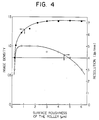
- the resolution and the image density both reach their respective maximum values when the average roughness falls in the range of 0.3 to 5.0 ⁇ m Rz. If the surface roughness of the carrier roll 11 exceeds 5 pm Rz, the transferring force relative to the non-magnetic toner 14 is increased and the layer of toner is formed in a relatively large thickness and, while the image is produced in high density, the image is liable to suffer from foggings. Further, since the amount of toner adhering to the sensitive material is excessive, the resolution is degraded.
- Prevention of the toner from conglomeration or aggregation and formation of a uniformly electrified toner layer can be achieved by moderating the force of pressure exerted on the metal plate blade 12 for contact with the carrier roll 11.
- Realisations of reproductions of images of very fine quality can be obtained using a one-component developing agent composed of a non-magnetic toner.
- the thickness of the layer of toner and the magnitude of electric charge assumed by the toner are important factors which also determine the quality of the image.
- the magnitude of electric charge exceeds 20 u C/g, the development is obtained with difficulty and the image density is degraded. If it is less than 2 ⁇ C/g, the image suffers from heavy fogging.
- the thickness of the toner layer is determined with a microscope and the magnitude electric charge is determined by the blowoff method which comprises sucking the thin layer of toner formed on the surface of the developing roller and, during the suction, measuring the amount of electric charge escaping from the developing roller.
- a toner containing polyester, carbon, a charge regulating agent, etc. was used having an average particle size of 11.3 pm.
- the peripheral speed of the sensitive drum 15 and that of the carrier roll 11 were both 110 mm/sec and the distance, "b", between them was 0.2 mm.
- the thickness of the toner layer was 26 11m and the magnitude of charge determined by the suction blowoff method was -7.0 p C/g.
- the development of an image was effected by allowing the thin layer of toner formed as described above to be transferred without contact to the selenium sensitive drum 15 opposed to the carrier roll 11.
- the toner so transferred to the selenium sensitive drum 15 was transferred onto an ordinary sheet of paper and fixed by the well-known method.
- the image density was 1.40, the resolution was 5 line pairs/mm, and the image had absolutely no discernible fogging. In a running test, the image reproduced after 40,000 duplications no discernible change.
- the development is carried out by following the procedure described above, except that the surface roughness of the carrier roll 1 was changed to 5.9 Rz.
- the thickness of the layer of toner was 120 um and the image density was 1.50, while the image suffered from fogging and the resolution was 3.2 line pairs/mm.
- the force of pressure exerted on the metal plate blade 12 for contact with the carrier roll 11 was set to 250 g/cm.
- the thickness of the layer of toner was 73 11 m and the occurrence of image fogging and the decline of resolution were prevented.
- the developing agent 15 formed an aggregate and the formation of a uniform thin layer of toner was obtained with difficulty after about 30,000 duplications.
- the polishing of the surface of the carrier roll was effected with a diamond cutter, for example until the surface roughness, Rz, falls below about 0.3 ⁇ m in the circumferential direction or in the axial direction of the carrier roll. Then, the polishing surface of the carrier roll was ready to be roughened by any desired method.
- This roughening of the surface of the carrier roll could be effected by various methods. For example, the method of sand blasting using alumina particles of a grain size of #240 to #3000, preferably #400 to #800 proved suitable.
- the irregularities formed on the surface of the carrier roll by the sand blasting technique for surface roughening have sharp ridges.
- the tips of such sharp ridges may be chipped or the developing agent may be attached fast to the roughened surface of the carrier roll and, as a result, the developing agent carrier may suffer a reduction in the service life, and the reproduced images may be degraded.
- the surface of the developing agent carrier which has undergone the treatment by sand blasting to a plating treatment, the sharp ridges of the irregularities on the surface of the carrier roll can be moderated and, at the same time, the surface hardness can be heightened. As a result, safe formation of images can be stably maintained.
- Various techniques are available for the plating treatment to be given for the purpose mentioned above.
- the hard chromium plating treatment preferably the electroless nickel plating treatment otherwise called the Catalytic Nickel Generation treatment
- the hard chromium plating treatment proves to be the best method in consideration of the resistance to wear. Since it is one form of the so-called electroplating treatment, the metal being deposited 'adheres preferentially in a larger thickness to the ridges of irregularities and at times fails to adhere to the grooves at all, This treatment, therefore, improves the resistance to wear and, as concerns the prevention of fast toner adhesion, proves effective more or less but cannot be expected to bring about any appreciable improvement.
- the electroplating treatment raises a problem that the quality of the produced plating hinges on the material of the roll and the condition of the pretreatment.
- the Catalytic Nickel Generation otherwise called the electroless plating or chemical plating, is capable of producing a uniform plating without reference to the irregularities of the surface.
- the Catalytic Nickel Generation treatment produces a plating of higher hardness than the plating of aluminum, for example, and is capable of further enhancing the hardness of the plating, when necessary, by a heat treatment.
- the plating when treated at a temperature of 400°C, for example, acquires the same degree of wear resistance as the hard chromium plating.
- the wear resistance is amply obtained when the thickness of the plating produced by this plating treatment falls in the range of 5 to 20 pm.
- Fig. 5 is a characteristic diagram showing the condition of the surface roughness of the developing agent carrier to be used in the developing apparatus of this invention.
- the part “b” of Fig. 5 shows the condition of surface roughness obtained by subjecting the roll of the surface roughness of the part "a” to a sand blasting treatment using #600 particles in grain size. In this case, the value of Rz is 1.56 ⁇ m.
- Fig. 6 is a characteristic diagram showing the condition of the surface roughness of a comparative roll.
- the characteristic of surface roughness which a roll of aluminum finished to a surface roughness of 6.3S and subjected, without any polishing treatment, to a sand blasting treatment using #600 particles in grain size acquires is shown in part "a" of Fig. 6.
- the treatments themselves have drawbacks of their own and confer peculiar undulations on the carrier surface and impair the uniformity of the formation of a toner layer. This lack of the uniformity is responsible for degradation of the quality of a reproduced image.
- a flexible developing agent carrier possessing surface roughness and hardness proper for the developing apparatus of this invention is obtained by subjecting the surface of a carrier roll to the treatments of polishing, roughening, and metal plating in the order mentioned as contemplated by the present invention.
- Sample No. 2 through Sample No. 5 were developing agent carriers obtained by following the procedure of Sample No. 1, except that the sand blasting treatment was effected by using alumina particles of #400 in grain size as No. 2, alumina particles of #600 in grain size as No. 3, alumina particles of #800 in grain size as No. 4, and alumina particles of #1000 in grain size as No. 5 respectively.
- the surface roughness falls in the range of 0.3 to 5.0 11m, preferably 0.4 to 3.0 pm.
- the developing apparatus according to the present invention not only gives highly desirable reproduced images but also permits uniform and stable images to be reproduced for a long period of time.
- the developing apparatus of this invention shows absolutely no discernible sign of such defects as fast adhesion of toner to the carrier roll, degradation of image, and abrasion of the surface of the developing agent carrier in a copy life test of 40,000 to 60,000 duplications.
Landscapes
- Physics & Mathematics (AREA)
- General Physics & Mathematics (AREA)
- Dry Development In Electrophotography (AREA)
Applications Claiming Priority (6)
| Application Number | Priority Date | Filing Date | Title |
|---|---|---|---|
| JP60060928A JPH0646331B2 (ja) | 1985-03-27 | 1985-03-27 | 現像装置の製造方法 |
| JP60928/85 | 1985-03-27 | ||
| JP61836/85 | 1985-03-28 | ||
| JP60061836A JPS61221769A (ja) | 1985-03-28 | 1985-03-28 | 現像装置 |
| JP60143504A JP2557826B2 (ja) | 1985-06-29 | 1985-06-29 | 現像装置 |
| JP143504/85 | 1985-06-29 |
Related Child Applications (1)
| Application Number | Title | Priority Date | Filing Date |
|---|---|---|---|
| EP88107899.2 Division-Into | 1988-05-18 |
Publications (3)
| Publication Number | Publication Date |
|---|---|
| EP0196231A2 EP0196231A2 (en) | 1986-10-01 |
| EP0196231A3 EP0196231A3 (en) | 1987-01-14 |
| EP0196231B1 true EP0196231B1 (en) | 1989-06-28 |
Family
ID=27297335
Family Applications (2)
| Application Number | Title | Priority Date | Filing Date |
|---|---|---|---|
| EP86302265A Expired EP0196231B1 (en) | 1985-03-27 | 1986-03-26 | Developing apparatus |
| EP88107899A Expired - Lifetime EP0306618B1 (en) | 1985-03-27 | 1986-03-26 | Developing apparatus |
Family Applications After (1)
| Application Number | Title | Priority Date | Filing Date |
|---|---|---|---|
| EP88107899A Expired - Lifetime EP0306618B1 (en) | 1985-03-27 | 1986-03-26 | Developing apparatus |
Country Status (5)
| Country | Link |
|---|---|
| US (1) | US4866480A (ja) |
| EP (2) | EP0196231B1 (ja) |
| JP (1) | JPH0646331B2 (ja) |
| KR (1) | KR900001047B1 (ja) |
| DE (2) | DE3664169D1 (ja) |
Families Citing this family (30)
| Publication number | Priority date | Publication date | Assignee | Title |
|---|---|---|---|---|
| JPS62278578A (ja) * | 1986-05-26 | 1987-12-03 | Toshiba Corp | 現像装置 |
| US5148639A (en) * | 1988-07-29 | 1992-09-22 | Canon Kabushiki Kaisha | Surface roughening method for organic electrophotographic photosensitive member |
| JP3014103B2 (ja) * | 1989-07-17 | 2000-02-28 | ミノルタ株式会社 | 現像装置 |
| US5674408A (en) * | 1990-03-24 | 1997-10-07 | Ricoh Company, Ltd. | Developer carrier capable of forming microfields thereon and method of producing the same |
| JP3057299B2 (ja) * | 1991-03-22 | 2000-06-26 | 株式会社リコー | 画像形成方法 |
| US5450176A (en) * | 1993-05-20 | 1995-09-12 | Mita Industrial Co., Ltd. | Developing device with rigid member toner limiting means |
| AU3426895A (en) | 1994-10-17 | 1996-05-02 | Canon Kabushiki Kaisha | Toner container, toner container assembling method, process cartridge, and electrophotographic image forming apparatus |
| WO1996025692A1 (en) | 1995-02-17 | 1996-08-22 | Michael Francis Gaylord | Electroless plated magnetic brush roller for xerographic copiers, printers and the like |
| JP3200325B2 (ja) * | 1995-04-12 | 2001-08-20 | シャープ株式会社 | 現像装置 |
| US5819145A (en) * | 1995-07-31 | 1998-10-06 | Ricoh Company, Ltd. | Image forming device for forming a uniform toner layer on a developing roller |
| EP0856781B1 (en) * | 1997-01-31 | 2004-08-11 | Seiko Epson Corporation | Developing unit |
| JPH11194618A (ja) * | 1997-11-10 | 1999-07-21 | Canon Inc | 画像形成装置 |
| JPH11219032A (ja) * | 1998-02-03 | 1999-08-10 | Sharp Corp | 現像装置 |
| US6702423B2 (en) | 1998-05-27 | 2004-03-09 | Canon Kabushiki Kaisha | Cleaning device for inkjet printing head, cleaning method for inkjet printing head, inkjet recording apparatus, and wiper |
| JP3588563B2 (ja) * | 1999-03-31 | 2004-11-10 | キヤノン株式会社 | 現像剤担持部材、それを用いた現像装置及び画像形成装置 |
| JP2001281985A (ja) * | 2000-03-30 | 2001-10-10 | Sharp Corp | 現像装置 |
| ATE396429T1 (de) * | 2000-04-10 | 2008-06-15 | Seiko Epson Corp | Bilderzeugungsgerät wobei eine ac-spannung an das entwicklerelement angelegt wird |
| US6341420B1 (en) | 2000-08-02 | 2002-01-29 | Static Control Components, Inc. | Method of manufacturing a developer roller |
| US6539193B1 (en) * | 2001-08-23 | 2003-03-25 | Toshiba Tec Kabushiki Kaisha | Developing apparatus and image forming apparatus for stably forming a developer layer on a developer device |
| US6725007B2 (en) * | 2001-10-01 | 2004-04-20 | Canon Kabushiki Kaisha | Developing assembly and image-forming apparatus |
| GB0308198D0 (en) | 2003-04-09 | 2003-05-14 | Chiron Srl | ADP-ribosylating bacterial toxin |
| US7013104B2 (en) | 2004-03-12 | 2006-03-14 | Lexmark International, Inc. | Toner regulating system having toner regulating member with metallic coating on flexible substrate |
| US7236729B2 (en) | 2004-07-27 | 2007-06-26 | Lexmark International, Inc. | Electrophotographic toner regulating member with induced strain outside elastic response region |
| JP5067846B2 (ja) * | 2007-07-18 | 2012-11-07 | 株式会社リコー | 現像装置、プロセスカートリッジおよび画像形成装置 |
| EP2093628A2 (en) * | 2008-02-20 | 2009-08-26 | Seiko Epson Corporation | Development roller, development device, and image forming apparatus |
| EP2093629A3 (en) * | 2008-02-20 | 2010-03-10 | Seiko Epson Corporation | Development roller, development device, and image forming apparatus |
| JP2009265360A (ja) * | 2008-04-25 | 2009-11-12 | Konica Minolta Business Technologies Inc | 現像装置および画像形成装置 |
| US9158228B2 (en) * | 2011-09-16 | 2015-10-13 | Ricoh Company, Ltd. | Development device and image forming apparatus incorporating same |
| JP2013137500A (ja) * | 2011-11-28 | 2013-07-11 | Ricoh Co Ltd | 現像装置及び画像形成装置 |
| JP2013200551A (ja) * | 2012-02-22 | 2013-10-03 | Ricoh Co Ltd | 現像装置、画像形成装置及びプロセスカートリッジ |
Citations (1)
| Publication number | Priority date | Publication date | Assignee | Title |
|---|---|---|---|---|
| EP0193069A1 (en) * | 1985-02-20 | 1986-09-03 | Kabushiki Kaisha Toshiba | Developing apparatus |
Family Cites Families (35)
| Publication number | Priority date | Publication date | Assignee | Title |
|---|---|---|---|---|
| US2518645A (en) * | 1947-09-04 | 1950-08-15 | Richard J Shanahan | Journal lubricator |
| US3572288A (en) * | 1968-08-07 | 1971-03-23 | Xerox Corp | Development apparatus |
| US3651758A (en) * | 1969-12-17 | 1972-03-28 | Moore Business Forms Inc | Ink transfer system |
| US3863603A (en) * | 1974-01-07 | 1975-02-04 | Ibm | Magnetic brush roll having resilient polymeric surface |
| US3974554A (en) * | 1975-05-16 | 1976-08-17 | Xerox Corporation | Quadrangular trihelicoid gravure roll |
| US4100884A (en) * | 1976-02-25 | 1978-07-18 | Ricoh Company, Ltd. | Rubber developer roller using single component toner |
| US4136637A (en) * | 1977-03-09 | 1979-01-30 | Xerox Corporation | Continuous contrast development system |
| JPS5451846A (en) * | 1977-09-30 | 1979-04-24 | Ricoh Co Ltd | Electrostatic latent image developing device |
| JPS5492747A (en) * | 1977-12-29 | 1979-07-23 | Minolta Camera Co Ltd | Pressure fixing device of powder lmages |
| US4217769A (en) * | 1978-10-10 | 1980-08-19 | Consolidated Papers, Inc. | Method of forming a coating application roll |
| US4377332A (en) * | 1979-04-20 | 1983-03-22 | Canon Kabushiki Kaisha | Developing device |
| JPS5614260A (en) * | 1979-07-16 | 1981-02-12 | Canon Inc | Developing device |
| US4325627A (en) * | 1979-12-19 | 1982-04-20 | Savin Corporation | Method and apparatus for liquid-developing latent electrostatic images |
| DE3107055A1 (de) * | 1980-03-04 | 1982-01-07 | Canon K.K., Tokyo | "entwicklungsvorrichtung" |
| US4410259A (en) * | 1980-03-08 | 1983-10-18 | Mita Industrial Co., Ltd. | Apparatus for developing latent electrostatic image |
| JPS5764764A (en) * | 1980-10-09 | 1982-04-20 | Canon Inc | Dry type development device |
| US4380966A (en) * | 1980-10-11 | 1983-04-26 | Canon Kabushiki Kaisha | Development apparatus |
| JPS5766455A (en) * | 1980-10-11 | 1982-04-22 | Canon Inc | Development device |
| JPS5786869A (en) * | 1980-11-20 | 1982-05-31 | Canon Inc | Developing device |
| JPS57165866A (en) * | 1981-04-07 | 1982-10-13 | Toshiba Corp | Developing device |
| US4459009A (en) * | 1981-07-27 | 1984-07-10 | Xerox Corporation | Apparatus, process for charging toner particles |
| JPS58153973A (ja) * | 1982-03-10 | 1983-09-13 | Toshiba Corp | 現像装置 |
| JPS58216278A (ja) * | 1982-06-11 | 1983-12-15 | Olympus Optical Co Ltd | 画像形成装置 |
| US4419959A (en) * | 1982-09-29 | 1983-12-13 | Am International, Inc. | Magnetic toner retainer means |
| US4624545A (en) * | 1982-10-15 | 1986-11-25 | Ricoh Company, Ltd. | Developing device with regulated developer supply |
| JPS5994352U (ja) * | 1982-12-14 | 1984-06-27 | 株式会社リコー | 現像装置 |
| JPS6033578A (ja) * | 1983-08-04 | 1985-02-20 | Toshiba Corp | 現像装置 |
| JPS6051853A (ja) * | 1983-08-31 | 1985-03-23 | Toshiba Corp | 現像装置 |
| JPS6051844A (ja) * | 1983-08-31 | 1985-03-23 | Toshiba Corp | 現像装置 |
| EP0138458B2 (en) * | 1983-09-30 | 1992-04-29 | Kabushiki Kaisha Toshiba | Developing apparatus |
| US4558943A (en) * | 1983-11-07 | 1985-12-17 | Xerox Corporation | Developer roller |
| JPS60113273A (ja) * | 1983-11-24 | 1985-06-19 | Ricoh Co Ltd | 現像剤層厚制御装置 |
| JPS60229070A (ja) * | 1984-04-27 | 1985-11-14 | Toshiba Corp | 現像装置 |
| GB2163371B (en) * | 1984-08-07 | 1988-04-07 | Ricoh Kk | Developing electrostatic latent images |
| US4696255A (en) * | 1984-08-07 | 1987-09-29 | Ricoh Company, Ltd. | Developing apparatus |
-
1985
- 1985-03-27 JP JP60060928A patent/JPH0646331B2/ja not_active Expired - Lifetime
-
1986
- 1986-03-18 KR KR1019860002004A patent/KR900001047B1/ko not_active IP Right Cessation
- 1986-03-26 EP EP86302265A patent/EP0196231B1/en not_active Expired
- 1986-03-26 DE DE8686302265T patent/DE3664169D1/de not_active Expired
- 1986-03-26 US US06/844,373 patent/US4866480A/en not_active Expired - Lifetime
- 1986-03-26 EP EP88107899A patent/EP0306618B1/en not_active Expired - Lifetime
- 1986-03-26 DE DE8888107899T patent/DE3687461T2/de not_active Expired - Lifetime
Patent Citations (1)
| Publication number | Priority date | Publication date | Assignee | Title |
|---|---|---|---|---|
| EP0193069A1 (en) * | 1985-02-20 | 1986-09-03 | Kabushiki Kaisha Toshiba | Developing apparatus |
Also Published As
| Publication number | Publication date |
|---|---|
| EP0196231A2 (en) | 1986-10-01 |
| EP0306618A1 (en) | 1989-03-15 |
| EP0306618B1 (en) | 1993-01-07 |
| KR900001047B1 (ko) | 1990-02-26 |
| DE3664169D1 (en) | 1989-08-03 |
| JPH0646331B2 (ja) | 1994-06-15 |
| EP0196231A3 (en) | 1987-01-14 |
| DE3687461T2 (de) | 1993-04-29 |
| DE3687461D1 (de) | 1993-02-18 |
| US4866480A (en) | 1989-09-12 |
| JPS61219974A (ja) | 1986-09-30 |
| KR860007568A (ko) | 1986-10-15 |
Similar Documents
| Publication | Publication Date | Title |
|---|---|---|
| EP0196231B1 (en) | Developing apparatus | |
| US5557060A (en) | Developing device | |
| EP0138458B2 (en) | Developing apparatus | |
| US5495322A (en) | Electrophotographic developing apparatus which utilizes single-component developing material | |
| JPS59116769A (ja) | 現像装置 | |
| EP0992861B1 (en) | Developing agent carrier, developing unit, and image forming apparatus | |
| US4870461A (en) | Developing device and developer carrying member usable therewith | |
| EP0636950B1 (en) | Developing apparatus having rotatable developer supply member for developer carrying member | |
| JP3667591B2 (ja) | 現像装置に使用されるブレード、その製造方法及び製造用金型、当該ブレードを有する現像装置及び画像形成装置 | |
| JP2819611B2 (ja) | 現像装置及びこれに用いる現像剤担持体 | |
| US5666620A (en) | Developing device for peeling toner using peeling rotary member | |
| JP2843651B2 (ja) | 現像装置 | |
| JPH0321907B2 (ja) | ||
| JPH0772739A (ja) | 現像装置及びプロセスカートリッジ | |
| JP2760501B2 (ja) | 現像装置 | |
| JP2000267426A (ja) | 現像装置及び画像形成装置 | |
| JPS6180279A (ja) | 現像装置 | |
| JP2590951B2 (ja) | 一成分現像装置 | |
| JP3358643B2 (ja) | 現像装置および画像形成装置 | |
| JP2962622B2 (ja) | 画像形成装置 | |
| JP3049620B2 (ja) | 現像装置 | |
| JPS6073649A (ja) | 現像装置 | |
| JPH01198777A (ja) | 現像装置 | |
| JPH0736278A (ja) | 現像装置 | |
| KR20000000960A (ko) | 현상장치의 현상부재 및 그 제조방법 |
Legal Events
| Date | Code | Title | Description |
|---|---|---|---|
| PUAI | Public reference made under article 153(3) epc to a published international application that has entered the european phase |
Free format text: ORIGINAL CODE: 0009012 |
|
| 17P | Request for examination filed |
Effective date: 19860415 |
|
| AK | Designated contracting states |
Kind code of ref document: A2 Designated state(s): DE FR GB NL |
|
| PUAL | Search report despatched |
Free format text: ORIGINAL CODE: 0009013 |
|
| AK | Designated contracting states |
Kind code of ref document: A3 Designated state(s): DE FR GB NL |
|
| 17Q | First examination report despatched |
Effective date: 19871103 |
|
| GRAA | (expected) grant |
Free format text: ORIGINAL CODE: 0009210 |
|
| AK | Designated contracting states |
Kind code of ref document: B1 Designated state(s): DE FR GB NL |
|
| PG25 | Lapsed in a contracting state [announced via postgrant information from national office to epo] |
Ref country code: NL Effective date: 19890628 |
|
| REF | Corresponds to: |
Ref document number: 3664169 Country of ref document: DE Date of ref document: 19890803 |
|
| ET | Fr: translation filed | ||
| NLV1 | Nl: lapsed or annulled due to failure to fulfill the requirements of art. 29p and 29m of the patents act | ||
| PLBE | No opposition filed within time limit |
Free format text: ORIGINAL CODE: 0009261 |
|
| STAA | Information on the status of an ep patent application or granted ep patent |
Free format text: STATUS: NO OPPOSITION FILED WITHIN TIME LIMIT |
|
| 26N | No opposition filed | ||
| REG | Reference to a national code |
Ref country code: GB Ref legal event code: IF02 |
|
| REG | Reference to a national code |
Ref country code: GB Ref legal event code: 732E |
|
| REG | Reference to a national code |
Ref country code: FR Ref legal event code: TQ |
|
| PGFP | Annual fee paid to national office [announced via postgrant information from national office to epo] |
Ref country code: FR Payment date: 20050308 Year of fee payment: 20 |
|
| PGFP | Annual fee paid to national office [announced via postgrant information from national office to epo] |
Ref country code: GB Payment date: 20050323 Year of fee payment: 20 |
|
| PGFP | Annual fee paid to national office [announced via postgrant information from national office to epo] |
Ref country code: DE Payment date: 20050324 Year of fee payment: 20 |
|
| PG25 | Lapsed in a contracting state [announced via postgrant information from national office to epo] |
Ref country code: GB Free format text: LAPSE BECAUSE OF EXPIRATION OF PROTECTION Effective date: 20060325 |
|
| REG | Reference to a national code |
Ref country code: GB Ref legal event code: PE20 |