EP0195976B1 - Design support method and apparatus therefor - Google Patents
Design support method and apparatus therefor Download PDFInfo
- Publication number
- EP0195976B1 EP0195976B1 EP86103203A EP86103203A EP0195976B1 EP 0195976 B1 EP0195976 B1 EP 0195976B1 EP 86103203 A EP86103203 A EP 86103203A EP 86103203 A EP86103203 A EP 86103203A EP 0195976 B1 EP0195976 B1 EP 0195976B1
- Authority
- EP
- European Patent Office
- Prior art keywords
- design
- data
- memory
- graphic pattern
- reference data
- Prior art date
- Legal status (The legal status is an assumption and is not a legal conclusion. Google has not performed a legal analysis and makes no representation as to the accuracy of the status listed.)
- Expired - Lifetime
Links
- 238000013461 design Methods 0.000 title claims description 391
- 238000000034 method Methods 0.000 title claims description 76
- 230000015654 memory Effects 0.000 claims description 172
- 238000012545 processing Methods 0.000 claims description 40
- 238000003860 storage Methods 0.000 claims description 24
- 230000014759 maintenance of location Effects 0.000 claims description 5
- 230000001502 supplementing effect Effects 0.000 claims 1
- 238000009434 installation Methods 0.000 description 44
- 239000003638 chemical reducing agent Substances 0.000 description 42
- 239000003086 colorant Substances 0.000 description 14
- 238000012937 correction Methods 0.000 description 4
- 238000006467 substitution reaction Methods 0.000 description 3
- 241000282414 Homo sapiens Species 0.000 description 1
- 108091029480 NONCODE Proteins 0.000 description 1
- 230000000052 comparative effect Effects 0.000 description 1
- 238000012790 confirmation Methods 0.000 description 1
- 230000001419 dependent effect Effects 0.000 description 1
- 238000012938 design process Methods 0.000 description 1
- 239000011810 insulating material Substances 0.000 description 1
- 238000012552 review Methods 0.000 description 1
- 239000004065 semiconductor Substances 0.000 description 1
- 239000000126 substance Substances 0.000 description 1
Images


Classifications
-
- G—PHYSICS
- G06—COMPUTING; CALCULATING OR COUNTING
- G06F—ELECTRIC DIGITAL DATA PROCESSING
- G06F17/00—Digital computing or data processing equipment or methods, specially adapted for specific functions
-
- G—PHYSICS
- G06—COMPUTING; CALCULATING OR COUNTING
- G06T—IMAGE DATA PROCESSING OR GENERATION, IN GENERAL
- G06T19/00—Manipulating 3D models or images for computer graphics
Definitions
- the present invention relates to design support method and apparatus therefor, and more particularly to design support method and apparatus therefor which enable a designer to rapidly retrieve design data and reflect restrictions on design references without failure.
- a display screen for a design object and a display screen for an input menu of design parameters are independent from each other and design data are displayed on split screens or a plurality of CRT screens.
- design data are displayed on split screens or a plurality of CRT screens.
- rapid and accurate entry of the design parameters is permitted but no consideration is paid on a check of validity of the design parameters.
- piping data are retrieved by a computer designed for piping path design and a pipe interval calculated based on pipe diameters and thicknesses of heat insulating materials.
- design parameters are combined to introduce comparative values to design references and they are displayed but the comparison with the design reference for each pipe should be done by a designer.
- Brown Boveri Review vol. 71, no. 3/4, March/April 1984, pages 154-159, discloses a collision check in a CAD system for power plant design. It is checked whether components, pipework and free spaces do not collide with one another. The results are printed out by the computer as lists, stating the names of any colliding parts and the coordinates and type of collision.
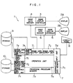
- Fig. 1 shows one embodiment of the design support apparatus of the present invention.
- the design support apparatus 1 supports design of layout of devices and pipes in a plant, and comprises display units (CRT) 2A and 2B, image display controllers 3 and 5, a processor (for example, computer) 7, a console panel (for example, keyboard) 8 and external storages 9 and 10.
- display units CRT
- processor for example, computer
- console panel for example, keyboard
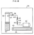
- FIG. 2 An example of a display screen of the CRT 2A is shown in Fig. 2. It shows a step in a course of design in which an operator has entered design data on installation positions and sizes of devices 36, 37, 38 and 40 and a pipe 41A from the console panel 8.
- the display screen displays graphic patterns of parts such as those devices and pipes. It is noted that even devices or apparatuses in a plant are called "parts" in the specification. Hatched areas are restriction areas which are feature of the present invention and will be described later.
- An area 46 displays devices and/or pipes whose installation positions the operator has not yet defined. This will also be explained later.
- the image display controller 3 has an image data memory 4 and is connected to the display unit 2A.
- the image display controller 3 reads out image data stored in the image data memory 4, and drives the display unit 2A to display the read image data on the screen of the display unit 2A.
- the image display controller 5 has an image data memory 6 and is connected to the display unit 2B. The operation of the image display controller 5 is same as that of the image display controller 3.
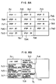
- the processor 7 has an operation unit 7a, a processing procedure memory 7b, an intermediate data memory 7c, an input unit 7d, a design data search code output unit 7e, a design data input unit 7f, a design reference data search code output unit 7g, a design reference data input unit 7h, image data output units 7i and 7j and a design data output unit 7k.
- the processing procedure memory 7b stores therein a program for a processing procedure shown by flow charts of Figs. 5 - 9.
- the console panel 8 is connected to the input unit 7d.
- the image data memories 4 and 6 are connected to the image data outputs 7i and 7j, respectively.
- the external storage 9 is a data base which contains plant design data and design data for devices and pipes in the plant, and it is connected to the design data search code output unit 7e and the design data input unit 7f.
- Figs. 3, 4 and 5 show examples of the design data stored in the external memory 9.
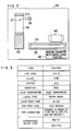
- Fig. 3 shows design data on a system HD shown by a design object code or line code "HD9".
- the design data for other systems of the plant are also stored in the external storage 9.
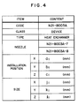
- Figs. 4 and 5 show examples of design data on the devices used in the system HD of Fig. 3, stored in the external storage 9.
- Fig. 4 shows the design data on a heat exchanger shown by a code "N21-B003A", and Fig.
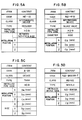
- FIG. 5A shows the design data on a reducer shown by a part code "RE-10".
- the design data on the device shown in Fig. 4 is read out after the design data of the line code "HD9" of Fig. 3 have been read, in connection with the design data of the line code "HD9".
- the design data on the device shown in Fig. 5 are read out after the design data of Fig. 3 or Fig. 4 have been read, in connection with the design data of Fig. 3 or Fig. 4.
- the design data in the reducer shown by the part code "RE-10" contain no position data (X, Y, Z) (design parameters), because the operator has not yet entered the position of the reducer from the console panel 8 and the design parameters have not yet been defined.
- Fig. 5B shows design data for a sluice valve shown by a part code "N21-F10”.
- Fig. 5C shows design data for a tank shown by a part code "A-22”, and
- Fig. 5D shows design data for a nozzle shown by a part code "N21-B003A-7”.
- the external storage 10 shown in Fig. 10 is a data base which stores therein various design reference data for the layout of the pipes of the plant and is stored to the design reference search code output unit 7g and the design reference data input unit 7h.
- Figs. 6A to 6C show examples of the design reference data stored in the external storage 10.
- the design reference data Nos. 1, 2 and 3 each has data on a restriction item, the number of condition data, condition data, conclusion data and a design reference.
- the design reference data Nos. 1 and 3 relate to the system HD.
- the design reference data No. 2 relates to the reducer.
- the design reference data for other systems and devices of the plant are similarly stored.
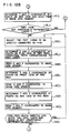
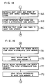
- the processing procedure memory 7b shown in Fig. 1 stores therein steps 11 to 24 of the design support processing procedure program shown in Fig. 7.
- An operator of the design support apparatus 1 manipulates the console panel 8 to enter a line code of the design object (design object item), for example, the line code "HD9" of the system HD, and a display form of a graphic pattern to be displayed on the display unit, to the processor 7 (step 11).
- the display form of the graphic pattern may be (1) display in accordance with a drafting method such as a three-plane method, (2) display in accordance with an isometrical projection method or (3) display in accordance with a perspection method.
- the design data of the line code for the design object and the design data of the related part codes are read from the external storage 9 by the operation unit 7a and stored in the design data input unit 7f (step 12).
- the design reference data for the design data stored in the design data input unit 7f is read out from the external storage 10 by the processor 7 and stored in the design reference data input unit 7h (step 13).
- the operation unit 7a causes the display unit 2A to display the graphic pattern of the design object item in the display form designated by the operator in the step 11, in accordance with the design data stored in the design data input unit 7f and the design reference data input unit 7h (step 14). Restriction areas derived from the device and parts such as pipes of the design object are displayed on the screen of the display unit 2A (step 15). If a part whose installation position has not yet been determined, that is, which has an undefined parameter is included at this stage, the design data of the part having the undefined parameter is displayed (step 16).
- the design references related to the design data of the part having the undefined parameter are displayed (step 17).
- the operator enters appropriate data for the undefined parameter while he/she takes the displayed restriction areas into account (step 18).
- a graphic pattern of the part having the undefined parameter is displayed on the display screen in accordance with the data entered by the operator (step 19).
- the restriction area for the part whose parameter was supplemented by the operator is displayed on the display screen (step 20).
- the operation unit 7a checks if any of the parts displayed on the screen is within the restriction area (step 21). If a part is within the restriction area, a comment indicating a violation to the design reference is displayed with the violated portion being highlighted, and the process returns to the step 18 (step 22).
- the operation unit 7a checks whether there is another line code of the design object (step 24), and if there is, the process returns to the step 11 to repeat the design, and if there is no such line data, the design process is terminated.
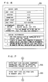
- the above steps 11 to 24 are stored in predetermined address areas of the processing procedure memory 7b shown in Fig. 8A, that is, in the memories 7b1 to 7b14.
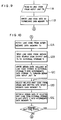
- Fig. 9 illustrates the processing in the step 11 of Fig. 7.
- the operator designates a design object item to which design is to be proceeded (for example, line code "HD9", through the console panel 8).
- the design object item entered by the operator is latched in the input unit 7d of the processor 7.
- the operation unit 7a temporarily stores the design object item inputted to the input unit 7d to a predetermined memory area (design object item memory area) 7c1 of the intermediate data memory 7c.
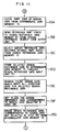
- Fig. 10 illustrates the processing in the step 12 of Fig. 7.
- the design data handled in the step 12 (and the step 11) are stored in the memory areas 7c1 - 7c8 of the intermediate data memory 7c shown in Fig. 8B.
- the operation unit 7a reads out the line code "HD9" stored in the memory area 7c1 of the intermediate data memory 7c (step 12A). Then, the operation unit 7a sends the line code "HD9" to the external storage 9 through the design data search code output unit 7e (step 12B).
- the operation unit 7a retrieves the design data (shown in Fig.
- step 12C the design object item relating to the line code "HD9" from the design data stored in the external storage 9, reads the retrieved design data into the processor 7 through the design data input unit 7f and stores it into the memory area 7c2 (design data memory area) of the intermediate data memory 7c (step 12C).
- the operation unit 7a retrieves the part code (excluding the line code) from the design data for the line code "HD9” stored in the memory area 7c2 of the intermediate data memory 7c (step 12D).
- the part codes "A-22" (tank), "N-21-B003A” (heat exchanger), "RE-10” (intermediate device) and "N21-F10” (sluice valve) are retrieved from the design data of Fig. 3.
- the code may be defined to one which has an alphabetic character at the beginning and is represented by both alphabetic and numeric characters.
- the part code design data for the part codes retrieved from the design object item design data shown in Fig. 3 are read from the external storage 9 and are stored in the memory area 7c2 of the intermediate data memory 7c (step 12E).
- the part code design data (shown in Figs. 4, 5A, 5B and 5C) for the part codes “A-22", “N21-B003A”, “RE-10” and “N21-F10” shown in Fig. 3 are retrieved and stored into the memory area 7c2 of the intermediate data memory 7c.
- the steps 12D, 12E and 12F are repeated until the part codes in the design data retrieved within the range of the design object item are exhausted.
- the step 12F the presence or absence of the part code which is stored in the predetermined memory area of the intermediate data memory 7c and for which the design data has not yet been retrieved is checked. If there is a part code for which the design data has not yet been retrieved, the processing of the steps 12D and 12E is performed. This processing is repeated until the design data for the design object item stored in the step 12C and the design data for the part codes stored in the step 12E are exhausted.
- the part code "N21-B003A-7" (nozzle) is included in the design data (Fig.
- step 12E the design data (Fig. 5D) for that part code is retrieved from the external storage 9 and stored into the memory area 7c2 of the intermediate data memory 7c.
- the part code "N21-B003A-8" is included in the design data for "N21-B003A” (heat exchanger), but since the part code is included in the system other than the system HD, it is detected in the step 12F and no processing is carried out in the steps 12D and 12E.
- step 12F when it is determined that the part codes included in the design data stored in the memory area 7c2 of the intermediate data memory 7c within the range of the design object item (line code), the process goes to the step 13 shown in Fig. 7.
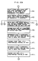
- the processing of the step 13 (retrieval of the design reference data) carried out by the operation unit 7a comprises seven steps 13A - 13G shown in Fig. 11. Those steps 13A - 13G are sequentially carried out. It the step 13 of Fig. 7, the desired design reference data is written into the predetermined memory area (design reference data memory area) of the intermediate data memory 7c from the design reference data memory 10, by referencing the design data stored in the step 12 in the design data memory area of the intermediate data memory 7c.
- step 13A the system of the design data and the part codes (“HD9”, “A-22”, “N21-B003A”, “N21-F10”, “RE-10”, ----- ) stored in the step 12 in the memory area 7c2 of the intermediate data memory 7c are read out (step 13A).
- the part codes are then sent from the design reference data search code output unit 7g to the design reference data memory 10 (step 13B).
- the design reference data which includes the desired line code or any of the desired part codes are selected from the design reference data stored in the design reference data memory 10 (step 13C). In the step 13C, the numbers 1 - 3 of Figs. 6A - 6C and other related design reference data are selected.
- the design reference data numbers selected, the restriction items, the number of condition data, the condition data, conclusion data ana the design references are stored in the predetermined memory area (design reference data memory area) of the intermediate data memory 7c through the design reference data input unit 7h (step 13D).
- Those selected design reference data are checked for the part code design data which satisfies all of the conditions in the condition data column (step 13E), and if there is such a design reference data, a flag is set for that design reference data to indicate that the conditions are met (step 13F). For example, for the design reference data No. 1 shown in Fig.
- the line code and part codes which have three items, class of condition data, temperature and system and the items relate to pipe, high temperature and HD, respectively (which part codes are stored in the design data memory area 7c2 of the intermediate data memory 7c) are searched. If there is design data for the line code or part code which satisfied the conditions of the three items, the code of the corresponding design data is entered to the code name column of the conclusion data for the design reference data No. 1. For the design reference data No. 1 of Fig. 6A, the contents of the three items of the condition data are equal to the contents of the items, i.e. class of the line code "HD9", temperature and system shown in Fig. 2. Thus, "HD9" is entered as the code name for the conclusion data to the design reference data No. 1.
- the contents of the three items of the condition data are equal to the contents of the items, i.e. class of line code "HD9", system and diameter shown in Fig. 2.
- “HD9” is entered as the code name of the conclusion data.
- the contents of the two items of the condition data are equal to the contents of the items, i.e. class of part code "RE-10" and type shown in Fig. 5A.
- "RE-10" is entered as the code name of the conclusion data.
- the design reference data Nos. 1 - 3 having the codes entered in the code name columns of the conclusion data are prepared.
- the flag set operation in the step 13F may be substituted by entering the code name into the code name column of the conclusion data.
- step 13G of the step 13 only those design reference data which meet the condition are left in the memory area 7c3 of the intermediate data memory 7c, and the those design reference data in the memory area 7c3 which do not meet the conditions are erased.
- the design reference data other than Nos. 1 - 3 shown in Figs. 6A, 6B and 6C are erased from the memory area 7c3.
- the operation unit 7a carries out the processing of the step 14.
- the step 14 performs graphic representation and display of the structure of the design object item, and comprises steps 14A, 14B, 14C1 - 14R1, 14C2 - 14J2 and 14C3 - 14J3 shown in Figs. 12A - 12D.
- Fig. 12A those design data which have part codes are selected from the design data stored in the memory area 7c2 of the intermediate data memory 7c (step 14A).
- part codes “N21-B003A”, “N21-F10”, “RE-10", “A-22” and “N21-B003A-7” are selected.
- the design data included in the selected part codes are stored in a new memory area 7c4 of the intermediate data memory 7c.
- a step 14B selects a graphic representation form, that is, one of (1) three-plane method, (2) isometrical projection method and (3) perspection method in accordance with with a graphic representation form select signal (stored in the intermediate data memory 7c) entered by the operator in the step 11 through the console panel 8.
- the graphic representation form is selected by the operator in the step 11, although it may be selected in the step 14B.
- the representation by the three-plane method is selected in accordance with the input signal.
- the processing of steps 14C1 - 14R1 is carried out.
- the part codes whose data on the installation position parameter and the size parameter have been determined, and the installation positions and the sizes relating to those part codes are read out (step 14C1).
- the part codes "N21-B003A”, “NF21-F10", “A22” and “N21-B003A-7” having their parameters determined are selected, and the installation positions of the part codes and the sizes are read out.
- the size for "N21-F10" is a diameter
- "N21-B003A-7” has only the installation position shown in Fig. 5D although the size thereof is stored.
- a plan view of the devices is prepared based on the installation position and the size data of the fetched code (step 14D1). More specifically, X and Y coordinates of a number of points which constitute lines in the plan view are determined based on the X and Y installation position coordinates and the size data of the devices.
- the resulting X and Y coordinates of the points constituting the lines in the plan view are sent from the image data output unit 7i (Fig. 1) to the image data memory 4 (step 14E1).
- the X and Y coordinates of the plan view of the device determined in the step 14D1 are stored in the image data memory 4 of Fig. 1.
- a plan view arranged at a predetermined position of the device is prepared based on the installation position coordinates and the size data (step 14F1).
- X and Z coordinates of a number of points constituting lines in a front view are determined based on the X and Z installation position coordinates and the size data of the device.
- a step 14G1 the X and Z coordinates of the points constituting the lines are sent from the image data output unit 7i to the image data memory 4.
- the image data memory 4 stores the X and Z coordinates of those points.
- a side view arranged at a predetermined position of the device is prepared based on the installation position coordinates and the size data (step 14H1).
- Fig. 12B shows a continued portion to the flow chart of Fig. 12A.
- a step 14H1 the Y and Z coordinates of a number of lines which constitute the side view are determined based on the Y and Z installation position coordinates and the size data of the device.
- the Y and Z coordinates of the points constituting the lines are sent from the image data output unit 7i to the image data memory 4 (step 14I1).
- the Y and Z coordinates of those points are stored in the image data memory 4.
- step 14J1 the presence or absence of the part code which has both the installation position coordinate and the size data but is not graphically represented is checked (step 14J1). If there is such a part code, the steps 14C1 - 14J1 are repeated.
- the part codes "A-22", “N21-F10", “N21-B003A” and “N21-B003A-7” are graphically displayed on the screen by the three-plane method.
- "RE-10" has the size already set although it is not shown in Fig. 5A. The installation position for "RE-10" has not yet been set by the operator. Accordingly, "RE-10" is not pertinent to the decision in the step 14J1 and it is not selected in the step 14C1 and not graphically displayed on the screen.
- step 14J1 if there is no part code which has the installation position coordinate and the size data and is not graphically represented, the process goes to a step 14K1.
- the two part codes of the part codes stored in the memory area 7c4 which are to be directly connected to the pipe in the sequence of pipes (see the item of pipe connection in Fig. 3) stored in the memory area 7c2.
- the part codes "N21-B003A-7" and "N21-F10" are selected.
- the X and Y coordinates of a number of points which constitute lines in the plan view of the pipe paths by which the objects designated by the two selected part codes are connected are determined (step 14L1).
- the pipe paths may be determined by a method disclosed in Japanese Patent Application No. 58-187033 (corres.
- the design data of the related pipes stored in the external storage 9 are selected from the part codes of the two parts to be directly connected, and the X and Y coordinates of the pipes are determined based on the selected design data.
- the X and Y coordinates of the points constituting the lines of the pipe paths are sent from the image data output unit 7i to the image data memory 4 (step 14M1). Those coordinates are stored in the image data memory 4.
- the X and Z coordinates of a number of points which constitute lines of the pipe paths in a front view are determined (step 14N1).
- the resulting X and Z coordinates are sent from the image data output unit 7i to the image data memory 4 (step 14O1).
- Those coordinates are stored in the image data memory 4.
- the Y and Z coordinates of a number of points which constitute lines of the pipe paths in the side view are determined (step 14P1).
- Those coordinates are sent from the image data output unit 7i to the image data memory 4 (step 14Q1) and stored therein.
- the presence or absence of the pipe path which directly connects the two part codes and which has not yet been graphically represented is checked (step 14R1). If there is such a pipe path, the steps 14K1 - 14R1 are repeated. If all combinations of two part codes connected by the pipes are selected in the step 14K1, the process returns to the step 14L1 from the step 14R1 as shown by a broken line and repeats the steps 14L1 - 14R1.
- step 14R1 if there is no such pipe path, the process goes to a step 15A which will be explained later.
- the structures of the part codes having the installation positions and sizes determined and the pipe path which directly connects those two part codes are graphically represented.
- the graphic pattern representation by the three-plane method has been described.
- the graphic pattern representation by the isometrical method is now explained.
- In the isometrical projection drawing three orthogonal axes are projected to three axes angularly spaced by 120° from each other. If the selection of the isometric method is detected in the step 14B, the processing of steps 14C2 - 14J2 is carried out.
- the part code having both of the installation position coordinates and the size data, and the installation position coordinates and the size data for the part code are read from the design data having the part codes, selected and stored in the memory 7c4 (step 14C2).
- An isometric view arranged at a predetermined position of the device is prepared based on the installation position coordinates and the size data of the part code (step 14D2).
- X, Y and Z coordinates of a number of points which constitute lines of patterns are determined based on the X, Y and Z installation position coordinates and the size data of the device.
- the resulting X, Y and Z coordinates of the points constituting the lines of patterns are sent from the image data output unit 7i to the image data memory 4 (step 14E2).
- the X, Y and Z coordinates are stored in the image data memory 4.
- step 14F2 since "RE-10" has no installation position data, it is not selected in the step 14F2. If the there is such a part code, the steps 14C2 - 14F2 are repeated. If there is no such part code in the step 14F2, the process goes to a step 14G2. Of the codes stored in the memory 7c4, the two part codes which are to be directly connected by the pipe in the sequence of pipes (see Fig. 3) stored in the memory 7c2 are selected. The X, Y and Z coordinates of a number of points which constitute lines in the isometric view of the pipe paths which connect the objects designated by the two selected part codes are determined (step 14H2).
- step 14I2 The resulting X, Y and Z coordinates of the points constituting the lines of the pipe paths are sent from the image data output unit 7i to the image data memory 4 (step 14I2). Those coordinates are stored in the image data memory 4. Finally, the presence or absence of the pipe path which directly connects the two part codes and which is not graphically represented (step 14J2). If there is such a pipe path, the steps 14G2 - 14J2 are repeated. If there is no such pipe path in the step 14J2, the process goes to the step 15A shown in Fig. 13A.
- the selection of the perspective method is detected in the step 14B (Fig. 12A) and the steps 14C3 - 14J3 shown in Fig. 12D are carried out.
- the processing of the steps 14C3 - 14J3 are essentially identical to the processing of the steps 14C2 - 14J2 with substitution of "isometrical view" in the steps 14D2, 14E2 and 14H2 with “perspective view”. If the presence of the pipe path is detected in the step 14J3, the process goes to the step 14C3, and if the absence thereof is detected, the process goes to the step 15A shown in Fig. 13A.
- the perspective view an object is drawn by a perspective method as viewed from a one view point in the same manner as that human beings view.
- the operation unit 7a carries out the step 15 shown in Fig. 7.
- the structure of the part codes having the installation positions and the sizes thereof defined and the restriction area for the pipe path which directly connects those two part codes are graphically represented and displayed.
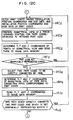
- the step 15 comprises steps 15A - 15C, 15D1 - 15M1, 15D2 - 15G2 and 15D3 - 15G3 as shown in Figs. 13A - 13D.
- All design references relating to the graphically represented part codes or pipe path of the step 14 are selected from the memory area 7c3 of the intermediate data memory 7c (step 15A). All selected design references are stored in the address area 7c5 of the intermediate data memory 7c (step 15B). In the present example, the design references relating to the design reference data Nos. 1 and 3 shown in Figs. 6A - 6C are selected.
- the graphic pattern representation form that is, one of (1) three-plane method, (2) isometrical method and (3) perspective method is determined in accordance with the graphic pattern representation form select signal entered from the console panel 8 (step 15C). In the present example, the three-plane method is selected.
- a plane view of a restriction area (inhibit area) for one design reference stored in the memory 7c5 is prepared based on the position of the restriction area and the size data thereof (step 15D1).
- the plan view of the restriction area of the design reference No. 1 shown in Fig. 6A that is, a device take-out space is prepared.
- the installation position and the size data of the device take-out space are contained in the design reference data No. 1 although they are not shown in Fig. 6A.
- the preparation of the plan view corresponds to determine X and Y coordinates of a number of points which constitute lines in the plan view of the restriction area.
- the plan view of the device take-out space is prepared.
- data for designating colors and intensities are added to the X and Y coordinates of the points which constitute the lines of the plan view of the restriction area (device take-out space).
- the colors are different from colors of the structures of the devices having codes and the pipe paths.
- the restriction area is displayed in yellow.
- the data for designating the X and Y coordinates, colors and intensities are sent from the image data output unit 7i to the image data memory 4 (step 15F1).
- the X and Y coordinates of the plan view of the restriction area determined in the step 15D1 and the color and intensity data added in the step 15E1 are stored in the image data memory 4.
- a front view arranged at a predetermined position of the restriction area (device take-out space) is next prepared based on the installation position coordinates and the size data (step 15G1).
- the X and Z coordinates of a number of points which constitute lines in the front view are determined based on the X and Z installation position coordinates of the restriction data and the size data thereof.
- the data to designate the colors e.g.
- step 15I1 The image data memory 4 stores the data for designating the X and Z coordinates, colors and intensities of those points.
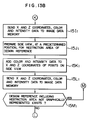
- step 15J1 a side view arranged at a predetermined position of the restriction area is prepared based on the installation position coordinates and the size data.
- step 15J1 the Y and Z coordinates of a number of points which constitute lines in the side view are determined based on the Y and Z installation position coordinates of the restriction area and the size data thereof.
- Data for designating colors (e.g. yellow) and intensities are added to the Y and Z coordinates of the points which constitute the lines (step 15K1).
- the data for designating the Y and Z coordinates, colors and intensities of the points are sent from the image data output unit 7i to the image data memory 4 (step 15L1).
- the Y and Z coordinates of those points are stored in the image data memory 4.
- step 15M1 the presence or absence of the design reference including the restriction area of the design reference which was stored in the step 15B in the memory area 7c5 and which is not graphically represented is checked (step 15M1). If there is such a design reference, the steps 15D1 - 15M1 are repeated.
- design reference No. 3 shown in Fig. 6C for which the processing of the steps 15D1 - 15M1 is carried out again.
- the design reference No. 3 shown in Fig. 6C defines the restriction area with relation to a wall of the area in which the design object item is arranged. The coordinates of the points which constitute lines of the pattern of the wall are determined by the processor 7 prior to the start of the processing of the step 11 of Fig.
- the restriction area for the design reference No. 3 of Fig. 6C is graphically represented in the plan view, front view and side view based on the size data "space from the wall not less than 300 mm" and "installation position of the wall".
- the coordinates of the points which constitute the lines of the patterns are sent to the image data memory 4 and stored therein.
- step 15M1 if the absence of the design reference which includes the non-graphically represented restriction area is detected, the process goes to the step 16A shown in Fig. 14.
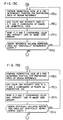
- step 15C If the isometrical method is selected in the step 15C, the steps 15D2 - 15G2 shown in Fig. 13 are carried out.
- An isometrical view arranged at a predetermined position of the restriction area of one of design references stored in the step 15B in the memory area 7c5 is prepared based on the installation position coordinate of the restriction area and the size data thereof (step 15D2).
- the X, Y and Z coordinates of a number of points which constitute lines of patterns are determined based on the X, Y and Z installation position coordinates of the restriction area and the size data thereof.
- Data for designating colors (e.g. yellow) and intensities are added to the X, Y and Z coordinates of the points which constitute the lines of the patterns (step 15E2).
- the data for designating the X, Y and Z coordinates, colors and intensities are sent from the image data output unit 72 to the image data memory 4 (step 15F2).
- the X, Y and Z coordinates sent in the step 15F2 are stored in the image data memory 4.
- the presence or absence of the design reference including the non-graphically represented restriction area of the design reference stored in the step 15B in the memory area 7c5 is checked (step 15G2). If there is such a design reference, the processing of the steps 15D2 - 15G2 is repeated. If the absence of such design reference is detected in the step 15G2, the step 16A is carried out.
- the perspective method is selected in the step 15C (Fig. 13A) and the steps 15D3 - 15G3 shown in Fig. 13D are carried out.
- the processing of the steps 15D3 - 15G3 is shown in Fig. 12D.
- Those steps are essentially identical to the steps 15D2 - 15G2 of Fig. 13C with substitution of "isometrical view" in the step 15D2 by "perspective view”.
- the step 15D3 is carried out, and if the absence of such design reference is detected, the step 16A shown in Fig. 14 is carried out.
- the data for designating colors and intensities are added to the coordinates of the points of the patterns represented in the three-plane method, isometrical method or perspective method of the step 14, and the coordinates are sent to the image data memory.
- the operation unit 7a carries out the step 16, that is, displays the design data having undefined parameter.
- the step 16 comprises steps 16A, 16B and 16C as shown in Fig. 14.
- the part code of the design data having the undefined parameters e.g. installation position coordinate and size data
- the item (installation position and size) of the undefined parameters are retrieved from the design data stored in the memory area 7c2 of the intermediate data memory 7c (step 16A).
- the part codes and the items of the undefined parameters are stored in the memory area 7c6 of the intermediate data memory 7c (step 16B).
- "RE-10" and the item "installation position" of the undefined parameter are stored in the memory 7c6. While the size of "RE-10" is not shown in Fig.
- step 16C all of the part codes stored in the memory area 7c6 and the items of the undefined parameters therefor are sent from the image data output unit 7i to the image data memory 4. Those part codes are stored in the image data memory 4.
- Fig. 15 shows a detail of the step 17 shown in Fig. 7.
- the step 17 comprises steps 17A - 17D and displays the design data and design references to the design object item.
- the operation unit 7a carries out the step 17.
- the design data of the design object item stored in the memory area 7c2 of the intermediate data memory 7c are read out.
- the design data are then sent from the image data output unit 7j to the image data memory 6 (step 17B).
- the design data of the pipe system for the line code "HD9" (Fig. 3) is sent to the image data memory 6 in the step 17B.
- the image data memory 6 stores the design data of the design object item.
- step 17C the design references for the design object item stored in the memory area 7c3 of the intermediate data memory 7c are read out.
- the design references are then sent from the image data output unit 7j to the image data memory 6 (step 17D).
- the image data memory 6 stores the design references for the design object item.
- the design reference Nos. 1 - 3 shown in Figs. 6A - 6C are sent from the image data output unit 7j to the image data memory 6 in the step 17D.
- the image display controller 3 of Fig. 1 fetches the data for storing the coordinates, colors and intensities of the images stored in the image data memory 4 in the steps 14 - 16, and sequentially displays those images on the display device 2A.
- Fig. 2 shows an example of the display on the display device 2A displayed after the steps 14 - 16. It is a plan view of the design object item (system HD) derived in the steps 14 and 15.
- the heat exchanger (part code N21-B003A) 36 having the nozzle (part code N21-B003A-7) 37, sluice valve (part code N21-F10) 38, tank (part code A-22) 40 and pipe 41A which connects the nozzle 37 to the sluice valve 38 are graphically displayed.
- the graphic patterns of the heat exchanger 36, nozzle 37, sluice valve 38 and tank 40 are derived in the steps 14C1 - 14E1.
- the graphic pattern of the pipe 41A is derived in the steps 14L1 - 14Q1.
- Numeral 35 denotes a wall located in a section in which the devices are arranged.
- the graphic pattern of the wall 35 is previously determined and stored in the image data memory 4.
- the restriction area 42 is for the design reference No. 1 shown in Fig. 6A.
- the restriction area 43 is for the design reference No. 3 shown in Fig. 6C.
- Those restriction areas are determined in the steps 15D1 - 15F1.
- the undefined parameter 46 is determined in the steps 16A - 16C.
- the image display controller 5 of Fig. 1 fetches the data for designating the coordinates, colors and intensities of the images stored in the image data memory 6 and displays the images on the display device 2B.
- Fig. 17 shows an example of display of the design data and design references derived in the steps 17A - 17D.
- the operator enters from the console panel 8 the data for the item of the undefined parameter of the device designated by the part code including the undefined parameter in the image (Fig. 2) displayed on the display device 2A, together with the part codes. Since the part codes such as devices which include the undefined parameters and the items of the undefined parameters are displayed on the display device 2A, the operator can easily recognize the devices which include the undefined parameters and the items of the undefined parameters so that he/she can enter the required data in a short time. "RE-10 (installation position)" is displayed in the column of the undefined parameter of the image shown in Fig. 2.
- the operator enters the X, Y and Z coordinates of the installation position of the reducer (RE-10) together with the part code "RE-10" from the console panel 8. Since the restriction areas 42 and 43 are displayed on the display device 2A, the operator can enter the installation position of the reducer in a short time such that it does not go into the restriction areas 42 and 43 and it meets the design references 2 displayed on the display device 2B.
- the design data and the design reference are displayed on the screen (Fig. 16) of the display device 2B, the operator can very easily position the parts for the part codes which include the undefined parameters such that they meet the design references. Thus, the design time can be shortened.
- the operation unit 7a carries out the step 18 shown in Fig. 7 (entry of data of undefined parameter of design data).
- the step 18 comprises steps 18A and 18B.
- the data for the part codes which include the undefined parameters and the items of the corresponding undefined parameters, which were entered by the operator are fetched into the processor 7 through the input unit 7d (step 18A).
- the data for the part codes and the items of the undefined parameters are stored in the memory area 7c7 of the intermediate data memory 7c (step 18B).
- the operation unit 7a of Fig. 1 then carries out the step 19, that is, graphic representation and display of the objects to which the parameters were supplemented and the pipe path to be connected thereto.
- the step 19 is similar to the processing shown in Figs. 12A - 12D, which are referenced here.
- the operation unit 7a first determines the selection of the graphic representation form in the step 14B. That is, the graphic representation form selected by the operator in the step 11 is checked in the step 14B. In the present example, the three-plane method is selected. The part codes of the design objects, size data and installation position coordinates thereof are fetched from the memory area 7c7 (step 14C1). Thus, the size data and the installation position coordinate of the reducer (RE-10) are fetched. In the step 19, the processing of the steps 14D1 - 14I1 is carried out as it is done in the step 14.
- step 19 which includes the steps 14D1 - 14I1, the plan view, front view and side view of the reducer (RE-10) are generated, and the coordinates of points constituting the lines of those views are sent to the image data memory 4, which stores those coordinates therein.
- step 14J1 of the step 19 the presence or absence of the part code which is stored in the memory area 7c1 and which is not graphically represented is checked. If there is such a part code, the steps 14D1 - 14I1 and 19B1 are repeated. If there is no such part code in the step 14J1, the process goes to the step 14K1.
- step 14K1 of the step 19 the part codes which are stored in the memory area 7c7 and the part codes which are directly connected to those part codes through pipes and which are stored in the memory area 7c4 are selected, by referencing the sequence of connection of pipes (Fig. 3) for the line code HD9 stored in the memory 7c2.
- "RE-10" and "A-22" are selected.
- the processing of the steps 14L1 - 14Q1 is carried out in the step 19 as well.
- the plan view, front view and side view of the pipe path which directly connects the objects corresponding to the two part codes (RE-10 and A-22 in the present example) are generated, and the coordinates of points constituting the lines of those views are sent to the image data memory 4.
- the pipe path may be determined by the method disclosed in Japanese Patent Application No. 58-187033 mentioned above.
- the step 14R1 of the step 19 the presence or absence of the pipe path which directly connects the part code stored in the memory area 7c7 and the part code which is stored in the memory area 7c4 and and which is to be connected to said part code, and which pipe path is not graphically represented, is checked. If there is such a pipe path, the steps 19C1, 14L1 - 14Q1 and 19D1 are repeated. If there is no such pipe path in the step 19D1, a step 20A shown in Fig. 19A is carried out. In the present example, since "RE-10" and "N21-F10" are connected, the steps 14K1, 14L1 - 14Q1 and 14R1 are repeated in the step 19.
- step 14C2 of the step 19 the code of the object and the size data and installation position coordinate of the object, which are stored in the memory area 7c7 are fetched.
- the steps 14D2 and 14E2 of the step 19 are then carried out.
- step 14F2 of the step 19 the presence or absence of the code which is stored in the memory area 7c7 and which is not graphically represented is checked. If there is such a code, the steps 14C2, 14D2, 14E2 and 14F2 are repeated. If there is no such code in the step 14F2, the process goes to the step 14G2, which identical to the step 14K1.
- step 14J2 which is identical to the step 14R1 of the step 19 is carried out. If the decision in the step 14J2 is yes, the steps 14G2, 14H2, 14I2 and 14J2 are repeated. If the decision in the step 14J2 is no, the process goes to the step 20 of Fig. 7.
- step 14B of the step 19 If the selection of the perspective view is detected in the step 14B of the step 19, the processing similar to that of Fig. 12D is carried out.
- the steps for the perspective view of the step 19 are essentially same as those for the isometrical view of the step 19 with the substitution of "isometrical view" by "perspective view". Accordingly, detailed explanation thereof is omitted here. If the decision in the step 14J3 of the step 19 is no, the process goes to the step 20 of Fig. 7.
- the operation unit 7a carries out the processing of the step 20 of Fig. 7.
- the processing of the step 20 (graphic representation and display of restriction area relating to supplemented parameters) is similar to that shown in Figs. 13A - 13D.
- all design references relating to the part codes or pipe paths graphically represented in the step 19 are fetched from the memory area 7c3 of the intermediate data memory 7c.
- the processing of the steps 15B and 15C is sequentially carried out. If the selection of the three-plane method is detected in the step 15C of the step 20, the steps 15D1 - 15M1 of the step 20 are carried out.
- the steps 15D2 - 15G2 of Fig. 13C are carried out, and if the selection of the perspective view is detected in the step 15C, the steps 15D3 - 15G3 of Fig. 13D are carried out.
- step 15M1 of Fig 13B If the decision in the step 15M1 of Fig 13B, the step 15G2 of Fig. 13C or the step 15G3 of Fig. 13D is no, the process goes to the step 21 of Fig. 7.
- the design reference No. 2 of Fig. 6B is selected in the step 15A of the step 20, and the restriction area for the design reference is graphically represented for the three-plane method.
- the image display controller 3 fetches the graphic data which were generated in the steps 19 and 20 and are stored in the image data memory 4 and displays them on the display device 2A.
- Fig. 20 shows an image displayed on the display device 2A after the steps 19 and 20.
- Numeral 39 denotes the reducer (RE-10).
- the pipes 41B and 41C connect the reducer 39 to the sluice valve 38 and the tank 40, respectively.
- the restriction areas 44 and 45 are for the design reference No. 2 shown in Fig. 6B. Since there is no undefined parameter, the undefined parameter 46 shown in Fig. 2 is no longer displayed.
- the operation unit 7a carries out the step 21 shown in Fig. 7.
- the violation or non-violation to the design reference by the part for the part code having the parameter thereof supplemented in the step 18 is checked.
- the coordinates of the patterns of the parts relating to the part codes stored in the memory area 7c7 and the pipe paths to be directly connected to those parts are fetched.
- the coordinates of the points of the patterns of the restriction areas for the design references relating to the part codes are fetched.
- the coordinates of the points of the patterns generated in the step 19 are also stored in the intermediate data memory 7c.
- the coordinates of the points of the patterns generated in the step 14 and the patterns of the restriction areas generated in the steps 15 and 20 are also stored in the intermediate data memory 7c.
- the positional relationship between the objects for the part codes and the restriction areas for the design references is determined. Violation or non-violation to the design references by the objects for the part codes is checked. The result is stored in the memory area 7c8 of the intermediate data memory 7c. Finally, the presence or absence of the part code which is stored in the memory area 7c7 and for which violation/non-violation has not yet been checked is checked. If there is such a part code, the step 21 is repeated. If there is no such part code, the process goes to the step 22 or 23.
- the following processing is carried out in the step 21.
- "RE-10" has been stored in the memory area 7c7 as the part code which includes the undefined parameter.
- the violation or non-violation to the design references by the parameter supplemented to RE-10 has been checked.
- the design reference for the reducer (RE-10) 38 is shown by No. 2 in Fig. 6B.
- the coordinates of the points of the pattern of the restriction area (the value three times of the pipe diameter D is particularly important) for the design reference and the coordinates of the patterns of the pipes 41B and 41C to be connected to the reducer 39 are compared. If curved portions of the pipes 41B and 41C are outside of the restriction areas 44 and 45, non-violation to the design reference by the position of the reducer 39 is detected. If the curved portions are inside of the restriction areas, violation to the design reference by the position of the reducer 39 is detected.
- the process goes to the step 22.
- the step 22 is carried out by the operation unit 7a.
- the violated design reference and the violating portions of the pattern are displayed.
- the coordinates which violate the design reference are selected from the coordinates of the points of the patterns stored in the intermediate data memory 7c in the steps 19 and 20 and they are displayed on the screen of the display device 2A.
- Color codes (or intensities) which indicate the violation are added to the violating coordinates of the pattern selected by the operation unit 7a and the coordinates are sent to the image data memory 4.
- the violating area is displayed on the display device 2A in the predetermined color (or intensity).
- the violating area may be displayed only for the restriction area pattern or design object item pattern.
- the operation unit 7a also adds the violating part codes to the design reference together with the predetermined color code (or intensity) and sends them to the image data memory 6, which displays them on the display device 2B in the predetermined color (or intensity).
- the violating area is directly displayed on the pattern displayed on the screen of the display device 2A so that the operator can identify the violating area of the pattern.
- the operator while he/she looks at the screen on which the violating area is displayed in the step 22, corrects the item of the undefined parameter of the object which caused the violation, through the console panel 8.
- the correction is fetched into the processor 7 in the step 18A, and the steps 18 - 22 are repeated until non-violation is detected in the step 21. Since the design data and the design references are displayed even when the data for the item of the undefined parameter of the object which caused the violation is corrected, the operator can recognize the information from the screen and appropriately correct the data for the item of the undefined parameter.
- the decision in the step 21 may be made not only to those related to the parts for the part codes having their parameters supplemented in the step 18 but also to all part relating to the design object item for confirmation purpose.
- the data for the objects relating to the codes stored not only in the memory area 7c7 but also in the memory area 7c2 are fetched in the step 21.
- the above processing is repeated until all objects stored in the memory areas 7c2 and 7c7 have been checked for the violation.
- the steps 21 and 22 are carried out between the steps 15 and 16.
- the data for the item of the parameter suplemented in the step 18A is registered as the design data of the part code (step 23).
- the operation unit 7a fetches the data for the item of the parameter supplemented in the step 18 together with the code therefor, of the non-violating parts stored in the memory area 7c8 of the intermediate data memory 7c, and sends them from the design data output unit 7k to the external memory 9, which stores therein the data for the item of the parameter.
- the new data for the design data which do not violate the design reference are stored in the external memory 9 and the new data may be effectively utilized in the subsequent design.
- the correction data (correction to the design data) is stored into the external storage 9 in the step 23.
- the design for one design object item (system HD in the present example) is completed.
- the operation unit 7a is checked in the step 24 to determine whether any other design object item exists. If there is such a design object item, the operation unit 7a retrieve the remaining design object item stored in the intermediate data memory 7c and sends it from the output unit 7j to the image data memory 6.
- the image display controller 5 fetches the remaining design object item from the image data memory 6 and displays it on the display device 2B. When the remaining design object item is displayed, the image shown in Fig. 16 is erased. The operator selects one of the design object items displayed on the display device 2B and enters the line code thereof to the processor 7 through the console panel 8.
- the operation unit 7a again carries out the steps 11 - 24 shown in Fig. 7. If there is no design object item in the step 24, the operation unit 7a sends a message "no design object item" from the output unit to the image data memory 6. This message is displayed by the image display controller 5 on the display device 2B. This completes the design for all design object items.
- FIG. 19 An example of image displayed on the display device 2A in the present embodiment is shown in Fig. 19.
- the images which were displayed on the display devices 2A and 2B in the previous embodiment are now displayed concurrently on the single display device 2A.
- the present embodiment can attain the same advantages as those attained by the previous embodiment. Furthermore, since a portion of the hardware configuration can be saved, the design support apparatus can be simplified.
- a design reference data shown in Fig. 20 may be prepared, in which a move zone of a movable member is defined as an inhibit zone for installation of devices and pipes.
- a restriction area 47 is displayed on the display device 2A in accordance with the design reference data shown in Fig. 20.
- Fig. 21 shows a front view of arrangement of the devices shown in Fig. 18, and the like elements to those of Fig. 18 designate the like elements.
- a rail 44 for a whist crane 45 spans at the top of the screen 2A and the whist crane suspended by the rail 44 is laterally movable as shown by an arrow A.
- the whist crane 45 has a container 46 in which parts are accommodated.
- the whist crane 45 descends the container 46 as shown by an arrow B to allow an operator to take out parts from the container 46 or put the parts into the container 46.
- the pipes cannot be arranged in the move zone of the whist crane 45.
- the move zone of the movable member is not actually visible, it is easily overlooked in the design stage, and after the design was completed, it is redesigned while the operator takes the move zone of the movable member into account.
- the restriction area 47 includes a projection inhibit area 47A which indicates a descend zone of the container 46 of the whist crane 45. Since the operator can design while he/she takes the restriction area 47 into account, a design error is further lessened. While the whist crane 45 is shown in Fig. 21 for illustration purpose, the whist crane 45 need not be displayed so long as the restriction area 47 is displayed on the screen. Where a component of the design object is movable, a move zone of the component may be displayed as the restriction area.
- the embodiments herein described can be applied to the design of layout of devices and pipes in a plant such as chemical plant, nuclear power plant or heat power plant, and the design of layout of devices and pipes in a building. It may also be applied to the design of layout of devices and wirings in a semiconductor chip.
- the restriction area based on the design reference can be displayed on the screen, the operator can recognize the restriction area and design the layout of the objects in an effective way such that the objects do not enter into the restriction area. Accordingly, the violation to the restriction items for the design reference in the design of the layout of the objects is substantially reduced and the design time is substantially shortened.
Landscapes
- Engineering & Computer Science (AREA)
- Physics & Mathematics (AREA)
- Theoretical Computer Science (AREA)
- General Physics & Mathematics (AREA)
- Software Systems (AREA)
- General Engineering & Computer Science (AREA)
- Computer Hardware Design (AREA)
- Computer Graphics (AREA)
- Data Mining & Analysis (AREA)
- Databases & Information Systems (AREA)
- Mathematical Physics (AREA)
- Processing Or Creating Images (AREA)
- General Factory Administration (AREA)
- Management, Administration, Business Operations System, And Electronic Commerce (AREA)
Applications Claiming Priority (2)
| Application Number | Priority Date | Filing Date | Title |
|---|---|---|---|
| JP53764/85 | 1985-03-18 | ||
| JP60053764A JPH0638266B2 (ja) | 1985-03-18 | 1985-03-18 | 設計支援方法及びその装置 |
Publications (3)
| Publication Number | Publication Date |
|---|---|
| EP0195976A2 EP0195976A2 (en) | 1986-10-01 |
| EP0195976A3 EP0195976A3 (en) | 1988-12-14 |
| EP0195976B1 true EP0195976B1 (en) | 1994-08-03 |
Family
ID=12951880
Family Applications (1)
| Application Number | Title | Priority Date | Filing Date |
|---|---|---|---|
| EP86103203A Expired - Lifetime EP0195976B1 (en) | 1985-03-18 | 1986-03-11 | Design support method and apparatus therefor |
Country Status (5)
| Country | Link |
|---|---|
| US (1) | US4789944A (ja) |
| EP (1) | EP0195976B1 (ja) |
| JP (1) | JPH0638266B2 (ja) |
| KR (1) | KR940009382B1 (ja) |
| DE (1) | DE3650005T2 (ja) |
Families Citing this family (39)
| Publication number | Priority date | Publication date | Assignee | Title |
|---|---|---|---|---|
| US5050091A (en) * | 1985-02-28 | 1991-09-17 | Electric Editor, Inc. | Integrated electric design system with automatic constraint satisfaction |
| JPH0679318B2 (ja) * | 1986-09-30 | 1994-10-05 | 株式会社日立製作所 | 設計評価装置 |
| JPH0650515B2 (ja) * | 1987-06-19 | 1994-06-29 | 株式会社日立製作所 | 設計支援方法及びその設計支援装置 |
| US5544067A (en) * | 1990-04-06 | 1996-08-06 | Lsi Logic Corporation | Method and system for creating, deriving and validating structural description of electronic system from higher level, behavior-oriented description, including interactive schematic design and simulation |
| US5544066A (en) * | 1990-04-06 | 1996-08-06 | Lsi Logic Corporation | Method and system for creating and validating low level description of electronic design from higher level, behavior-oriented description, including estimation and comparison of low-level design constraints |
| US5572437A (en) * | 1990-04-06 | 1996-11-05 | Lsi Logic Corporation | Method and system for creating and verifying structural logic model of electronic design from behavioral description, including generation of logic and timing models |
| US5222030A (en) * | 1990-04-06 | 1993-06-22 | Lsi Logic Corporation | Methodology for deriving executable low-level structural descriptions and valid physical implementations of circuits and systems from high-level semantic specifications and descriptions thereof |
| US5557531A (en) * | 1990-04-06 | 1996-09-17 | Lsi Logic Corporation | Method and system for creating and validating low level structural description of electronic design from higher level, behavior-oriented description, including estimating power dissipation of physical implementation |
| US5870308A (en) * | 1990-04-06 | 1999-02-09 | Lsi Logic Corporation | Method and system for creating and validating low-level description of electronic design |
| US5623418A (en) * | 1990-04-06 | 1997-04-22 | Lsi Logic Corporation | System and method for creating and validating structural description of electronic system |
| US5220512A (en) * | 1990-04-19 | 1993-06-15 | Lsi Logic Corporation | System for simultaneous, interactive presentation of electronic circuit diagrams and simulation data |
| US5541849A (en) * | 1990-04-06 | 1996-07-30 | Lsi Logic Corporation | Method and system for creating and validating low level description of electronic design from higher level, behavior-oriented description, including estimation and comparison of timing parameters |
| US5553002A (en) * | 1990-04-06 | 1996-09-03 | Lsi Logic Corporation | Method and system for creating and validating low level description of electronic design from higher level, behavior-oriented description, using milestone matrix incorporated into user-interface |
| US5598344A (en) * | 1990-04-06 | 1997-01-28 | Lsi Logic Corporation | Method and system for creating, validating, and scaling structural description of electronic device |
| US5572436A (en) * | 1990-04-06 | 1996-11-05 | Lsi Logic Corporation | Method and system for creating and validating low level description of electronic design |
| US5555201A (en) * | 1990-04-06 | 1996-09-10 | Lsi Logic Corporation | Method and system for creating and validating low level description of electronic design from higher level, behavior-oriented description, including interactive system for hierarchical display of control and dataflow information |
| US5867399A (en) * | 1990-04-06 | 1999-02-02 | Lsi Logic Corporation | System and method for creating and validating structural description of electronic system from higher-level and behavior-oriented description |
| AU8395491A (en) * | 1990-07-12 | 1992-02-04 | First Graphics, Inc. | Method and apparatus for designing a distribution system for a building |
| US5557537A (en) * | 1990-07-12 | 1996-09-17 | Normann; Linda M. | Method and apparatus for designing and editing a distribution system for a building |
| US5227983A (en) * | 1990-07-12 | 1993-07-13 | First Graphics, Inc. | Method and apparatus for designing a distribution system for a building |
| WO1993022741A2 (en) * | 1992-04-29 | 1993-11-11 | First Graphics, Inc. | Method and apparatus for designing and editing a distribution system for a building |
| US5526517A (en) * | 1992-05-15 | 1996-06-11 | Lsi Logic Corporation | Concurrently operating design tools in an electronic computer aided design system |
| JPH07249748A (ja) * | 1994-03-14 | 1995-09-26 | Fujitsu Ltd | マスタースライス型lsiの設計装置 |
| WO1995034866A1 (en) * | 1994-06-14 | 1995-12-21 | Telefonaktiebolaget Lm Ericsson | A method and system for manipulating intelligent representations of real equipment within a graphical computer system |
| US5636133A (en) * | 1995-05-19 | 1997-06-03 | International Business Machines Corporation | Efficient generation of fill shapes for chips and packages |
| US6175948B1 (en) | 1998-02-05 | 2001-01-16 | Motorola, Inc. | Method and apparatus for a waveform compiler |
| US6772017B1 (en) * | 2000-01-20 | 2004-08-03 | Fisher-Rosemount Systems, Inc. | Tool for configuring and managing a process control network including the use of spatial information |
| US7536664B2 (en) | 2004-08-12 | 2009-05-19 | International Business Machines Corporation | Physical design system and method |
| US20090039407A1 (en) * | 2005-03-17 | 2009-02-12 | Vora Madhukar B | Vertically integrated flash EPROM for greater density and lower cost |
| US8150660B2 (en) * | 2007-05-01 | 2012-04-03 | M.E.P. Cad, Inc. | Methods and apparatuses for automatically selecting a pipe in a CAD drawing |
| US20100121614A1 (en) | 2007-05-01 | 2010-05-13 | M.E.P. Cad, Inc. | Methods and Apparatuses for Preprocessing a CAD Drawing |
| US8441502B2 (en) * | 2007-05-01 | 2013-05-14 | M.E.P. Cad, Inc. | Methods and apparatuses for resolving a CAD drawing conflict with an arm around |
| US8773425B2 (en) * | 2007-05-01 | 2014-07-08 | M.E.P. CAD Inc. | Methods and apparatuses for proposing resolutions to conflicts in a CAD drawing with reflections |
| US8224628B2 (en) * | 2007-05-01 | 2012-07-17 | M.E.P. Cad, Inc. | Methods and apparatuses for placing a flexible drop in a CAD drawing |
| US8600706B2 (en) | 2007-05-01 | 2013-12-03 | Auto Prep, Llc | Systems and methods for identifying crash sources in a CAD environment |
| AU2008248197B2 (en) | 2007-05-01 | 2011-12-01 | M.E.P. Cad, Inc. | Methods and apparatuses for handling a conflict in a CAD drawing |
| US8554520B2 (en) | 2007-05-01 | 2013-10-08 | Auto Prep, Llc | Systems and methods for differentiating and associating multiple drawings in a CAD environment |
| US9358411B2 (en) | 2011-05-27 | 2016-06-07 | Victaulic Company | Flexible dry sprinkler |
| WO2016083262A1 (de) * | 2014-11-24 | 2016-06-02 | Bayer Technology Services Gmbh | Verfahren zur konfiguration einer zur durchführung von wenigstens einer chemischen reaktion eingerichteten produktionsanlage |
Family Cites Families (5)
| Publication number | Priority date | Publication date | Assignee | Title |
|---|---|---|---|---|
| US4377849A (en) * | 1980-12-29 | 1983-03-22 | International Business Machines Corporation | Macro assembler process for automated circuit design |
| JPS58187033A (ja) | 1982-04-26 | 1983-11-01 | Nippon Telegr & Teleph Corp <Ntt> | 移動通信制御方式 |
| JPS5945575A (ja) | 1982-09-03 | 1984-03-14 | テレシス・コ−ポレ−シヨン・オブ・デラウエア・インコ−ポレ−テツド | コンピユ−タ利用設計装置およびそれによる設計方法 |
| JPS5966763A (ja) | 1982-10-08 | 1984-04-16 | Mitsubishi Yuka Eng Kk | 配管経路設計用小形電子計算機 |
| JPS6079470A (ja) | 1983-10-07 | 1985-05-07 | Hitachi Ltd | レイアウト支援装置 |
-
1985
- 1985-03-18 JP JP60053764A patent/JPH0638266B2/ja not_active Expired - Lifetime
-
1986
- 1986-03-11 DE DE3650005T patent/DE3650005T2/de not_active Expired - Fee Related
- 1986-03-11 EP EP86103203A patent/EP0195976B1/en not_active Expired - Lifetime
- 1986-03-12 US US06/838,957 patent/US4789944A/en not_active Expired - Lifetime
- 1986-03-17 KR KR1019860001937A patent/KR940009382B1/ko not_active IP Right Cessation
Also Published As
| Publication number | Publication date |
|---|---|
| DE3650005T2 (de) | 1994-11-17 |
| US4789944A (en) | 1988-12-06 |
| KR860007602A (ko) | 1986-10-15 |
| EP0195976A2 (en) | 1986-10-01 |
| JPH0638266B2 (ja) | 1994-05-18 |
| JPS61213969A (ja) | 1986-09-22 |
| KR940009382B1 (ko) | 1994-10-07 |
| EP0195976A3 (en) | 1988-12-14 |
| DE3650005D1 (de) | 1994-09-08 |
Similar Documents
| Publication | Publication Date | Title |
|---|---|---|
| EP0195976B1 (en) | Design support method and apparatus therefor | |
| US5006991A (en) | Method for making of design reference and apparatus therefor | |
| US4984180A (en) | Method for computer aided generator of design reference and apparatus therefor | |
| EP0246559B1 (en) | Method and apparatus for assisting layout design | |
| JP2856640B2 (ja) | 論理回路図エディタシステム | |
| US4992953A (en) | Computer assisted design method and apparatus | |
| US6480124B2 (en) | CAD data compressing method and apparatus thereof | |
| JPH0778809B2 (ja) | 設計支援方法およびその装置 | |
| JP3213486B2 (ja) | 配線経路決定方法 | |
| JPS61131171A (ja) | 図形エレメント選択装置 | |
| JP2966441B2 (ja) | 図面作成支援装置 | |
| EP0654745A2 (en) | Graphical display system for routing and repartitioning circuits during layout | |
| JPH07200641A (ja) | プラント設計支援方法及びその装置 | |
| JPH04291672A (ja) | 設計支援装置 | |
| JPH0896001A (ja) | フロー図編集装置 | |
| JP2646828B2 (ja) | 配置修正方式 | |
| JP3275018B2 (ja) | プログラム自動生成方法及びその装置並びにデータ入力方法及びその装置 | |
| JPH0638267B2 (ja) | 設計支援装置 | |
| JP2511535B2 (ja) | レイアウト設計支援装置 | |
| JP3242269B2 (ja) | 配線経路決定方法 | |
| JPH08123831A (ja) | 回路図データ編集方法 | |
| JP2914302B2 (ja) | 配線設計の配線制限表示方法 | |
| JPH06103499B2 (ja) | 設計支援装置 | |
| JPS62114061A (ja) | 設計支援方法 | |
| JPS6385863A (ja) | プラント据付手順決定支援方法及びその装置 |
Legal Events
| Date | Code | Title | Description |
|---|---|---|---|
| PUAI | Public reference made under article 153(3) epc to a published international application that has entered the european phase |
Free format text: ORIGINAL CODE: 0009012 |
|
| AK | Designated contracting states |
Kind code of ref document: A2 Designated state(s): DE FR GB |
|
| PUAL | Search report despatched |
Free format text: ORIGINAL CODE: 0009013 |
|
| AK | Designated contracting states |
Kind code of ref document: A3 Designated state(s): DE FR GB |
|
| 17P | Request for examination filed |
Effective date: 19881227 |
|
| 17Q | First examination report despatched |
Effective date: 19910114 |
|
| GRAA | (expected) grant |
Free format text: ORIGINAL CODE: 0009210 |
|
| AK | Designated contracting states |
Kind code of ref document: B1 Designated state(s): DE FR GB |
|
| REF | Corresponds to: |
Ref document number: 3650005 Country of ref document: DE Date of ref document: 19940908 |
|
| ET | Fr: translation filed | ||
| PLBE | No opposition filed within time limit |
Free format text: ORIGINAL CODE: 0009261 |
|
| STAA | Information on the status of an ep patent application or granted ep patent |
Free format text: STATUS: NO OPPOSITION FILED WITHIN TIME LIMIT |
|
| 26N | No opposition filed | ||
| REG | Reference to a national code |
Ref country code: GB Ref legal event code: IF02 |
|
| PGFP | Annual fee paid to national office [announced via postgrant information from national office to epo] |
Ref country code: FR Payment date: 20020228 Year of fee payment: 17 |
|
| PGFP | Annual fee paid to national office [announced via postgrant information from national office to epo] |
Ref country code: GB Payment date: 20020301 Year of fee payment: 17 |
|
| PGFP | Annual fee paid to national office [announced via postgrant information from national office to epo] |
Ref country code: DE Payment date: 20020328 Year of fee payment: 17 |
|
| PG25 | Lapsed in a contracting state [announced via postgrant information from national office to epo] |
Ref country code: GB Free format text: LAPSE BECAUSE OF NON-PAYMENT OF DUE FEES Effective date: 20030311 |
|
| PG25 | Lapsed in a contracting state [announced via postgrant information from national office to epo] |
Ref country code: DE Free format text: LAPSE BECAUSE OF NON-PAYMENT OF DUE FEES Effective date: 20031001 |
|
| GBPC | Gb: european patent ceased through non-payment of renewal fee |
Effective date: 20030311 |
|
| PG25 | Lapsed in a contracting state [announced via postgrant information from national office to epo] |
Ref country code: FR Free format text: LAPSE BECAUSE OF NON-PAYMENT OF DUE FEES Effective date: 20031127 |
|
| REG | Reference to a national code |
Ref country code: FR Ref legal event code: ST |