EP0186830A2 - Dispositif de réglage de la hauteur pour la ferrure de renvoi d'une ceinture de sécurité - Google Patents
Dispositif de réglage de la hauteur pour la ferrure de renvoi d'une ceinture de sécurité Download PDFInfo
- Publication number
- EP0186830A2 EP0186830A2 EP85115880A EP85115880A EP0186830A2 EP 0186830 A2 EP0186830 A2 EP 0186830A2 EP 85115880 A EP85115880 A EP 85115880A EP 85115880 A EP85115880 A EP 85115880A EP 0186830 A2 EP0186830 A2 EP 0186830A2
- Authority
- EP
- European Patent Office
- Prior art keywords
- blocking element
- guide rail
- slide
- carriage
- bearing
- Prior art date
- Legal status (The legal status is an assumption and is not a legal conclusion. Google has not performed a legal analysis and makes no representation as to the accuracy of the status listed.)
- Granted
Links
Images


Classifications
-
- B—PERFORMING OPERATIONS; TRANSPORTING
- B60—VEHICLES IN GENERAL
- B60R—VEHICLES, VEHICLE FITTINGS, OR VEHICLE PARTS, NOT OTHERWISE PROVIDED FOR
- B60R22/00—Safety belts or body harnesses in vehicles
- B60R22/18—Anchoring devices
- B60R22/20—Anchoring devices adjustable in position, e.g. in height
- B60R22/201—Anchoring devices adjustable in position, e.g. in height with the belt anchor connected to a slider movable in a vehicle-mounted track
- B60R22/202—Anchoring devices adjustable in position, e.g. in height with the belt anchor connected to a slider movable in a vehicle-mounted track the slider comprising spring-actuated locking means
- B60R22/203—Anchoring devices adjustable in position, e.g. in height with the belt anchor connected to a slider movable in a vehicle-mounted track the slider comprising spring-actuated locking means the locking means being movably mounted on the slider
Definitions
- the invention relates to a height adjustment device for a deflection fitting, which is preferably provided on the door post of a motor vehicle for seat belts, with a stationary guide rail with a double-C profile, a slide which can be displaced along the guide rail and to which the deflection fitting can be attached, and with one of the slides blocking element latching on the guide rail and extending through an opening in the slide.
- Such a height adjustment device is known from DE-GM 84 12 788, with which the fastening or deflection fitting for the shoulder belt of a seat belt can be adjusted gradually on the center or door jamb of the vehicle. It was criticized there that the slide can slide down automatically in the guide rail due to the tension exerted by the belt strap on the deflection fitting, so that a perfect engagement is not always guaranteed. With the known height adjustment device, the slide is to be brought to a stop when it is pulled down in the nearest opening by means of run-in bevels which are arranged between openings in the guide rail.
- the known blocking element is L-shaped in cross-section, the free end of one leg being inserted into the opening in question.
- the blocking element can be bent by the forces that occur if it is not of a very stable design.
- a large number of individual parts for moving the carriage, actuating the blocking element and pressing the parts in the locking position is required, so that the entire adjusting device is complicated, expensive, prone to failure and difficult, although even when the blocking element is snapped into an opening, it is safe Holding the deflection fitting is not guaranteed.
- the invention is therefore based on the object to improve the height adjustment device of the known type so that the overall device is lighter and can be composed of simple and few parts with perfect functionality.
- a row of locking teeth is provided in the longitudinal direction on the web connecting the C-profiles of the guide rail, against which one end of the blocking element located essentially within the guide rail can be latched and at the other end with one Lock key can be brought into engagement, and that the carriage is U-shaped in cross-section, the free legs of the U being guided in the respective C-profile of the guide rail.
- the cross-sectionally double-C-shaped guide rail has a high strength, which is used according to the invention particularly advantageously in that the blocking element rests against a locking tooth in the blocking position and yet remains essentially within the guide rail.
- the tensile or compressive forces at the moment of the accident are thus steered approximately in the longitudinal direction of the blocking element.
- the blocking element generally has a greater longitudinal extent than the transverse extent and the forces are guided in this longitudinal direction, because then there is less the risk that a leg angled by 90 °, as in the known L-shape, will be angled or kinked.
- the blocking element does not snap into an opening but is supported on the locking tooth in question at the time of the accident.
- the U-shaped cross-section of the carriage has the advantage when engaged with the guide rail that the carriage and the guide rail interlock under load, the carriage advantageously holding the two legs of the double-C guide rail together.
- the wall thickness of the guide rail can be made thinner and therefore lighter because parts of the load are also taken up by the slide.
- the slide is a simple part, which in principle can consist of a screw bolt with a large, thin head plate.
- the adjustment device according to the invention can thus be assembled from a few simple parts and ensures high security.
- the blocking element has two essentially straight end legs, is flat in cross-section and is Z-shaped and is articulated in the piercing area through the carriage.
- This form of the blocking element supports the derivation of the forces at the moment of the accident in the longitudinal direction of the element for support on the locking tooth that is currently engaged, while avoiding the risk of kinking.
- the Z-shaped bending of the blocking element can be carried out so that a risk of kinking is practically excluded.
- the articulated storage in the penetration area through the carriage can be carried out in various ways.
- a bearing shell can be arranged in the bearing opening in the bearing area, which supports the blocking element in an articulated manner in the desired manner.
- the blocking element has a bearing counterpart, through which an axis of rotation is inserted, which is located in another bearing counterpart of the guide housing is supported on the slide.
- the axis of rotation can be arranged in an articulated manner in a bearing counterpart with the advantage that the blocking element is kept precisely and geometrically defined with a not inconsiderable tolerance even during manufacture as a mass part.
- the tolerances of the blocking element mentioned play a role, for example, in the corresponding sheet thickness, and in the longitudinal extension of the blocking element, its thickness can be subject to certain fluctuations within the permissible tolerances without the smooth-running storage of such a blocking element being impaired.
- the bending radius during the Z-shaped deformation of the blocking element also plays only a minor role in this embodiment; ie you are independent of the bending radius in certain areas.
- the first radius of the blocking element facing the guide rail is on its underside a half-shell for a bearing shell inserted into a slot of the slide and if the end leg facing away from the guide rail the blocking element carries a plastic counter bearing.
- This counter bearing is expediently fastened to the blocking element and is supported in the push-through area of the slide on the aforementioned bearing shell, which is also located in the slot-shaped push-through opening.
- a preferred embodiment of the invention is further characterized in that an auxiliary tooth protruding toward the guide rail is attached to the end of the slide opposite the slot and comes to rest between two locking teeth.
- This auxiliary tooth is designed in the form of a projection and is stamped on the slide, for example. If the train or
- auxiliary tooth-shaped projection absorbs some of the forces that would otherwise deform the slide guide, which is generally made of plastic, and transfers these forces to a locking tooth other than the one against which the blocking element rests.
- a spring arranged between the slide and blocking element is advantageous for biasing the blocking element into the locked position.
- This can be a form spring, a compression spring or the like, depending on the arrangement and space for accommodating this spring. It ensures that the blocking element always tries to come into contact with a locking gear.
- the slide can only be moved along the guide rail when the blocking element is disengaged from the locking gear, and an actuating device which counteracts the biasing spring is used for this purpose.
- an actuating device which counteracts the biasing spring is used for this purpose.
- a plastic guide housing is arranged around the slide and has a holder for receiving the movable lock key with actuating projections which can be brought into engagement with the blocking element.
- the lock button moves the blocking element out of engagement with the locking gear when depressed, so that the carriage is then movable.
- the locking element immediately snaps under the force of the biasing spring against the nearest locking tooth.
- the actuating projections can be designed in the form of fingers that are thin and soft-elastic. As a result, the blocking element is rotated from the locked position into the open position and e.g. prevented from rattling by a forefinger while driving due to vibrations.
- the articulated mounting of the blocking element is arranged in the center of gravity of the blocking element.
- the Z-shaped bend of the blocking element is then advantageously provided in its center of gravity; or in other words, the storage is in the center of gravity of the blocking element. If any transverse forces occur, then in this embodiment there are practically no mass forces of the blocking element itself which would cause it to be thrown out of the latching position.
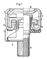
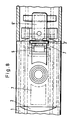
- the force-carrying parts are the stationary guide rail 1 with the double-C profile, in which a cross-sectionally U-shaped slide 2 is guided, the cross section of which can be clearly seen in FIGS. 1 and 6.
- the carriage 2 carries a holding bolt 10 in the center, as can also be seen from FIGS. 5a and 5b.
- a Z-shaped blocking element 5 with a flat cross section is inserted through a transverse slot 11 in the slide 2.
- the remaining parts are essentially not load-bearing.
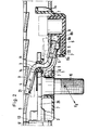
- a row of locking teeth 9, 9 ' is provided in the web 20 connecting the C profiles of the guide rail 1 in the longitudinal direction. It can be seen from FIGS. 2 and 4 that there are openings between the locking teeth 9, but these are not necessary, as the second embodiment according to FIGS. 6 to 8 shows, in particular FIG. 7.
- the blocking element 5 can be seen in a side view in FIG. 2. It has two essentially straight end legs 21, 22, between which the Z-shape is arranged in the center of gravity of the blocking element 5. With this central area, the blocking element 5 is inserted through the opening 11 in the carriage 2. It is biased in the latching position by the form spring 4. It can be seen how, in the latching position shown in solid lines in FIG. 2, the forces occurring at the moment of the accident are directed in the longitudinal direction of the blocking element 5 onto the locking tooth 9. As a result, high forces can be absorbed transversely (to the left in FIG. 2) in the longitudinal direction of the guide rail 1, forces which are caused on the retaining bolt 10 of the carriage 2 by the belt forces which are generated by the arrow F G.
- the piercing area in the carriage 2 is formed by the opening 11, which has the shape of a slot in both embodiments.
- a bearing shell 3 is in the slot 11 of the carriage 2 and ensures the articulated mounting of the Blocking element 5 over the first radius 14 facing the guide rail 1, which acts on the underside of the element 5 like a half-shell and is supported on the bearing shell 3.
- a plastic counter bearing 6 is fastened to the blocking element 5 and is supported with its front guide lug 12 on the bearing shell 3.
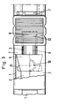
- the U-shaped slide 2 is shown in two different views and with one detail.
- the carriage 2 has an extremely simple shape. Both parts do not require any special material requirements.
- the slide was developed from a screw bolt with a thin head plate. This shape can still be seen approximately from FIG. 5a in a side view.
- the top plate 23 is punched out into the rectangular shape as shown in FIG. 5b, and the edges 24, which protrude into the adjacent C-profile of the guide rail 1, are embossed.
- the auxiliary tooth 13 shown as a detail in FIG. 5c and the push-through opening 11 for the blocking element 5 are also punched. (In the embodiment according to FIGS. 6 to 8, this auxiliary tooth 13 is not provided and is not required.)
- a plastic guide housing 7 is arranged around this U-shaped slide 2, in which the lock key 8 is also accommodated on the side of the frame shown in FIG.
- Guide lugs 7a shown on the left in FIG. 1 for guiding the carriage 2 are injection molded onto the ends of the housing 7.
- the lock key 8 is supported with a thin, soft-elastic forefinger 8a on the counterbearing 6 of the blocking element 5 and after its deformation with the main finger 8b on the blocking element 5 itself. If you press the lock button 8 down, if you want to move the carriage 2 along the guide rail 1, then the first finger 8a presses on the counter bearing 6 and after its deformation the main finger 8b on the blocking element 5, so that it is rotated from the locked position into the dashed position shown in FIG. 2 with broken lines (open position).
- the forefinger 8a has the purpose of "unlocking" the lock key 8.
- the bearing shell 3 for the articulated mounting of the blocking element 5 has already been discussed above.
- the plastic counter bearing 6 attached to the blocking element 5 completes the defined mounting of the blocking element 5 from the opposite side, that is to say from the right at the right end 22 of the blocking element 5.
- Both the first and the second embodiment of the height adjustment device come with very few parts, namely the force-bearing parts made of metal and four plastic parts described above (bearings 3, 3 ', counter bearings 6, 6', guide housing 7 and lock key 8).
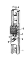
- the second embodiment is shown in FIGS. 6 to 8 and has numerous parts which are identical to the first embodiment according to FIGS. 1 to 4, so that the same reference numbers are used here and a repeated description is not necessary.
- the difference of the second embodiment compared to the first alternative is that here the articulated Storage of the elongated, flat and Z-shaped blocking element 5 does not have a bearing shell with a counter bearing but an integrally formed axis of rotation 3 'which is held in a bearing counter part 6' attached to the slide 2.
- the guide rail 1 has only the locking teeth 9, there are no slots or through-spaces between the individual locking teeth of the guide rail 1.
- the blocking element 5 can receive an advantageous back support on the tooth lying ahead (in FIG. 7 the tooth above the straight end 21). Thereby, a possible Ausknickgefahr of B locomotive kierimplantations reduced even further.
- the blocking element 5 can also be guided so precisely with respect to the slide 2 that the bending back of the blocking element on the slot support side in the slide 2 can be guided practically without play and exactly. This means that there is little deformation and quick locking under load.
- a compression spring 4 ' is used, which can be accommodated in the carriage 2 and, via a pin 26, on the left straight end 21 of the blocking element tes 5 is attached, guided and supported.
- the lock key 8 is pressed when actuated in the direction of the arrows 27, whereby the finger 28 is shifted from the position shown in solid lines to the position shown in dashed lines so that it comes into engagement with the key-side straight end 22 of the blocking element 5 and this can press into the unlocked position.
Landscapes
- Engineering & Computer Science (AREA)
- Mechanical Engineering (AREA)
- Seats For Vehicles (AREA)
- Automotive Seat Belt Assembly (AREA)
- Power-Operated Mechanisms For Wings (AREA)
- Bearings For Parts Moving Linearly (AREA)
Applications Claiming Priority (2)
| Application Number | Priority Date | Filing Date | Title |
|---|---|---|---|
| DE3447817 | 1984-12-29 | ||
| DE19843447817 DE3447817A1 (de) | 1984-12-29 | 1984-12-29 | Hoehenverstelleinrichtung fuer den umlenkbeschlag eines sicherheitsgurtes |
Publications (3)
| Publication Number | Publication Date |
|---|---|
| EP0186830A2 true EP0186830A2 (fr) | 1986-07-09 |
| EP0186830A3 EP0186830A3 (en) | 1987-12-02 |
| EP0186830B1 EP0186830B1 (fr) | 1990-09-19 |
Family
ID=6254119
Family Applications (1)
| Application Number | Title | Priority Date | Filing Date |
|---|---|---|---|
| EP85115880A Expired - Lifetime EP0186830B1 (fr) | 1984-12-29 | 1985-12-12 | Dispositif de réglage de la hauteur pour la ferrure de renvoi d'une ceinture de sécurité |
Country Status (9)
| Country | Link |
|---|---|
| US (1) | US4711498A (fr) |
| EP (1) | EP0186830B1 (fr) |
| JP (1) | JPH072454B2 (fr) |
| AU (1) | AU576036B2 (fr) |
| BR (1) | BR8506555A (fr) |
| CA (1) | CA1259967A (fr) |
| DE (2) | DE3447817A1 (fr) |
| ES (1) | ES8704402A1 (fr) |
| MX (1) | MX162429A (fr) |
Cited By (5)
| Publication number | Priority date | Publication date | Assignee | Title |
|---|---|---|---|---|
| DE3627087A1 (de) * | 1986-08-09 | 1988-03-10 | Audi Ag | Vorrichtung zur hoehenverstellung eines befestigungs-und umlenkbeschlages fuer sicherheitsgurte fuer kraftfahrzeuge |
| FR2640923A1 (fr) * | 1988-12-23 | 1990-06-29 | Daimler Benz Ag | |
| GB2241635A (en) * | 1990-02-21 | 1991-09-11 | Autoliv Kolb Limited | "Improvements in or relating to a pillar loop height adjuster" |
| EP0856441A1 (fr) * | 1997-01-30 | 1998-08-05 | Albert Griesemer | Dispositif de réglage en hauteur pour ancrages de renvoi de ceintures de sécurité de véhicules |
| EP2423057A1 (fr) * | 2010-08-25 | 2012-02-29 | Key Plastics Germany GmbH | Dispositif de reglage en hauteur de la patte de guidage de ceintures de securite |
Families Citing this family (15)
| Publication number | Priority date | Publication date | Assignee | Title |
|---|---|---|---|---|
| US4765651A (en) * | 1986-05-13 | 1988-08-23 | American Safety Equipment Corporation | Adjustable anchoring slide block assembly |
| JPS6353848U (fr) * | 1986-11-26 | 1988-04-11 | ||
| DE3713137A1 (de) * | 1987-04-16 | 1988-11-03 | Trw Repa Gmbh | Sicherheitsgurt-rueckhaltesystem fuer fahrzeuginsassen |
| DE3717177C2 (de) * | 1987-05-22 | 1997-09-18 | Autoflug Gmbh | Stufenweise rastender Höhenversteller |
| DE3802323C2 (de) * | 1988-01-27 | 1994-09-08 | Autoflug Gmbh | Fernbetätigbare Höhenverstellvorrichtung |
| DE3836327A1 (de) * | 1988-10-25 | 1990-04-26 | Albert Griesemer | Vorrichtung zur stufenweisen hoehenverstellung eines befestigungs- oder umlenkpunktes fuer einen sicherheitsgurt o. dgl. |
| JPH0290171U (fr) * | 1988-12-28 | 1990-07-17 | ||
| DE3927305A1 (de) * | 1989-08-18 | 1991-02-21 | Trw Repa Gmbh | Hoehenversteller fuer einen umlenkbeschlag |
| US5230534A (en) * | 1992-04-30 | 1993-07-27 | Allied-Signal Inc. | Adjustable seat belt turning loop anchorage with release button |
| US5931502A (en) * | 1997-01-15 | 1999-08-03 | Trw Vehicle Safety Systems Inc. | D-ring height adjuster |
| US5794977A (en) * | 1997-01-15 | 1998-08-18 | Trw Vehicle Safety Systems Inc. | D-ring height adjuster |
| US6123391A (en) * | 1999-03-31 | 2000-09-26 | Breed Automotive Technology, Inc. | Adjustable track and slide mechanism |
| DE10017970A1 (de) * | 2000-04-11 | 2001-10-18 | Kendrion Rsl Germany Gmbh | Vorrichtung zur Gurthöhenverstellung an Sicherheitsgurten |
| JP4249931B2 (ja) * | 2002-02-28 | 2009-04-08 | アイシン精機株式会社 | 車両用シートスライド装置 |
| US9004606B2 (en) * | 2013-04-17 | 2015-04-14 | H.O. Bostrom Company, Inc. | Emergency vehicle seat with integrated seat belt and height adjustable webbing guide |
Family Cites Families (15)
| Publication number | Priority date | Publication date | Assignee | Title |
|---|---|---|---|---|
| US1895222A (en) * | 1932-04-06 | 1933-01-24 | Aviat Patent And Res Corp | Airplane safety belt |
| DE2303222C3 (de) * | 1973-01-24 | 1983-11-10 | Adam Opel AG, 6090 Rüsselsheim | Sicherheitsgurtsystem für den Insassen eines Fahrzeugs |
| DE2657819A1 (de) * | 1976-12-21 | 1978-06-22 | Opel Adam Ag | Sicherheitsgurtanordnung, insbesondere in kraftfahrzeugen |
| FR2475905B1 (fr) * | 1980-01-11 | 1987-02-13 | Alix Maurice | Butee de tension pour ceinture de securite du type a enrouleur |
| DE3007986C2 (de) * | 1980-03-01 | 1983-09-15 | Bayerische Motoren Werke AG, 8000 München | Vorrichtung zum Verstellen eines karosseriefest angeordneten Gurtbeschlages |
| DE3012754C2 (de) * | 1980-04-02 | 1985-08-22 | Keiper Automobiltechnik Gmbh & Co Kg, 5630 Remscheid | Vorrichtung zum Verbinden des Schultergurtbandes eines Sicherheitsgurtes mit einem Träger, insbesondere einem Tür- oder Fensterholm eines Kraftfahrzeuges |
| DE3018442A1 (de) * | 1980-05-14 | 1981-11-19 | P.A. Rentrop Hubbert & Wagner, Fahrzeugausstattungen GmbH &Co KG, 3060 Stadthagen | Vorrichtung zur verstellung eines der schulter eines fahrzeuginsassen zugeorneten anlenkpunktes eines sicherheitsgurtes |
| JPS57176256U (fr) * | 1981-04-30 | 1982-11-08 | ||
| JPS5877761U (ja) * | 1981-11-24 | 1983-05-26 | 日本精工株式会社 | スル−アンカ−取付装置 |
| DE3151019C2 (de) * | 1981-12-23 | 1984-10-25 | Keiper Automobiltechnik Gmbh & Co Kg, 5630 Remscheid | Vorrichtung zum Befestigen des oberen Umlenkbeschlages für einen Dreipunktsicherheitsgurt an der Karosserie eines Kraftfahrzeuges |
| DE8401390U1 (de) * | 1984-01-19 | 1984-05-03 | Autoliv GmbH, 2200 Elmshorn | Hoehenverstellbare befestigungs- oder umlenkvorrichtung fuer den sicherheitsgurt eines sicherheitssystems in kraftfahrzeugen |
| DE8412788U1 (de) * | 1984-04-26 | 1984-09-27 | Autoliv GmbH, 2200 Elmshorn | Hoehenverstellbare befestigungs- oder umlenkvorrichtung fuer den sicherheitsgurt eines sicherheitssystems in kraftfahrzeugen |
| EP0150065B1 (fr) * | 1984-01-19 | 1988-05-11 | AUTOLIV GmbH | Dispositif d'ancrage ou de renvoi réglable en hauteur pour ceinture de sécurité de véhicule |
| GB8421049D0 (en) * | 1984-08-18 | 1984-09-19 | Britax Wingard Ltd | Anchorage means |
| EP0187225A3 (fr) * | 1984-11-15 | 1987-12-16 | Autoflug GmbH & Co Fahrzeugtechnik | Dispositif de réglage de la hauteur pour une ferrure de fixation ou de renvoi |
-
1984
- 1984-12-29 DE DE19843447817 patent/DE3447817A1/de active Granted
-
1985
- 1985-12-11 AU AU51085/85A patent/AU576036B2/en not_active Ceased
- 1985-12-12 DE DE8585115880T patent/DE3579799D1/de not_active Expired - Lifetime
- 1985-12-12 EP EP85115880A patent/EP0186830B1/fr not_active Expired - Lifetime
- 1985-12-13 CA CA000497613A patent/CA1259967A/fr not_active Expired
- 1985-12-25 JP JP60290913A patent/JPH072454B2/ja not_active Expired - Lifetime
- 1985-12-26 US US06/813,741 patent/US4711498A/en not_active Expired - Lifetime
- 1985-12-26 MX MX1096A patent/MX162429A/es unknown
- 1985-12-27 ES ES550498A patent/ES8704402A1/es not_active Expired
- 1985-12-27 BR BR8506555A patent/BR8506555A/pt not_active IP Right Cessation
Cited By (6)
| Publication number | Priority date | Publication date | Assignee | Title |
|---|---|---|---|---|
| DE3627087A1 (de) * | 1986-08-09 | 1988-03-10 | Audi Ag | Vorrichtung zur hoehenverstellung eines befestigungs-und umlenkbeschlages fuer sicherheitsgurte fuer kraftfahrzeuge |
| FR2640923A1 (fr) * | 1988-12-23 | 1990-06-29 | Daimler Benz Ag | |
| GB2241635A (en) * | 1990-02-21 | 1991-09-11 | Autoliv Kolb Limited | "Improvements in or relating to a pillar loop height adjuster" |
| GB2241635B (en) * | 1990-02-21 | 1993-11-03 | Autoliv Kolb Limited | Improvements in or relating to a pillar loop height adjuster |
| EP0856441A1 (fr) * | 1997-01-30 | 1998-08-05 | Albert Griesemer | Dispositif de réglage en hauteur pour ancrages de renvoi de ceintures de sécurité de véhicules |
| EP2423057A1 (fr) * | 2010-08-25 | 2012-02-29 | Key Plastics Germany GmbH | Dispositif de reglage en hauteur de la patte de guidage de ceintures de securite |
Also Published As
| Publication number | Publication date |
|---|---|
| AU576036B2 (en) | 1988-08-11 |
| JPH072454B2 (ja) | 1995-01-18 |
| EP0186830A3 (en) | 1987-12-02 |
| US4711498A (en) | 1987-12-08 |
| DE3447817A1 (de) | 1986-09-25 |
| CA1259967A (fr) | 1989-09-26 |
| MX162429A (es) | 1991-05-10 |
| DE3447817C2 (fr) | 1991-03-14 |
| ES8704402A1 (es) | 1987-04-01 |
| JPS61160337A (ja) | 1986-07-21 |
| BR8506555A (pt) | 1986-09-09 |
| DE3579799D1 (de) | 1990-10-25 |
| ES550498A0 (es) | 1987-04-01 |
| EP0186830B1 (fr) | 1990-09-19 |
| AU5108585A (en) | 1986-07-03 |
Similar Documents
| Publication | Publication Date | Title |
|---|---|---|
| EP0186830B1 (fr) | Dispositif de réglage de la hauteur pour la ferrure de renvoi d'une ceinture de sécurité | |
| DE2355497C2 (de) | Verschluß für Sicherheitsgurte | |
| DE2936468C2 (de) | Vorrichtung zur Befestigung eines Instruments in einer Vertiefung der Armaturentafel eines Kraftfahrzeugs | |
| DE3004150C2 (de) | Verschluß für einen Sicherheitsgurt | |
| DE3012937C2 (de) | Sicherheitsgurtverschluß | |
| DE3513807C2 (de) | Verriegelungsvorrichtung, insbesondere für verschwenkbare Kraftfahrzeugsitze | |
| DE3425669A1 (de) | Verriegelungsvorrichtung fuer eine hintersitz-rueckenlehne | |
| DE3337473A1 (de) | Gurtschloss fuer einen sicherheitsgurt | |
| EP0098435B1 (fr) | Elément de construction | |
| DE4421688C1 (de) | Gurtverschluß | |
| DE3128139C2 (de) | Verschluß für Sicherheitsgurte, insbesondere für Kraftfahrzeuge | |
| EP0129248B1 (fr) | Boucle pour ceinture de sécurité | |
| DE2713973A1 (de) | Feststellvorrichtung fuer gleitschienenfuehrungen | |
| DE2740200A1 (de) | Sicherheitsgurtschloss | |
| DE2945174A1 (de) | Umlenkbeschlag fuer den sicherheitsgurt eines rueckhaltesystems | |
| DE4005369C9 (de) | Schließeinrichtung an einer Fahrzeugtür | |
| DE3004169C2 (de) | Verschluß für Sicherheitsgurte | |
| DE2929803A1 (de) | Gurtschloss fuer einen sicherheitsgurt. | |
| DE2357090A1 (de) | Gurtschloss fuer sicherheitsgurt | |
| DE10201242A1 (de) | Schubladensicherungssystem | |
| DE3328798C2 (fr) | ||
| DE3516059C2 (de) | Höhenverstellvorrichtung für einen Umlenk- oder Befestigungsbeschlag | |
| DE3004159C2 (de) | Verschluß für Sicherheitsgurte | |
| DE29502987U1 (de) | Ausklinkbares Schnappschloß | |
| EP0187225A2 (fr) | Dispositif de réglage de la hauteur pour une ferrure de fixation ou de renvoi |
Legal Events
| Date | Code | Title | Description |
|---|---|---|---|
| PUAI | Public reference made under article 153(3) epc to a published international application that has entered the european phase |
Free format text: ORIGINAL CODE: 0009012 |
|
| AK | Designated contracting states |
Kind code of ref document: A2 Designated state(s): DE FR GB IT SE |
|
| PUAL | Search report despatched |
Free format text: ORIGINAL CODE: 0009013 |
|
| AK | Designated contracting states |
Kind code of ref document: A3 Designated state(s): DE FR GB IT SE |
|
| 17P | Request for examination filed |
Effective date: 19880115 |
|
| 17Q | First examination report despatched |
Effective date: 19881205 |
|
| ITF | It: translation for a ep patent filed | ||
| GRAA | (expected) grant |
Free format text: ORIGINAL CODE: 0009210 |
|
| AK | Designated contracting states |
Kind code of ref document: B1 Designated state(s): DE FR GB IT SE |
|
| GBT | Gb: translation of ep patent filed (gb section 77(6)(a)/1977) | ||
| REF | Corresponds to: |
Ref document number: 3579799 Country of ref document: DE Date of ref document: 19901025 |
|
| ET | Fr: translation filed | ||
| PLBI | Opposition filed |
Free format text: ORIGINAL CODE: 0009260 |
|
| 26 | Opposition filed |
Opponent name: AUTOFLUG GMBH & CO FAHRZEUGTECHNIK Effective date: 19910618 |
|
| ITTA | It: last paid annual fee | ||
| EAL | Se: european patent in force in sweden |
Ref document number: 85115880.8 |
|
| PLBN | Opposition rejected |
Free format text: ORIGINAL CODE: 0009273 |
|
| STAA | Information on the status of an ep patent application or granted ep patent |
Free format text: STATUS: OPPOSITION REJECTED |
|
| 27O | Opposition rejected |
Effective date: 19950411 |
|
| PGFP | Annual fee paid to national office [announced via postgrant information from national office to epo] |
Ref country code: FR Payment date: 19971120 Year of fee payment: 13 |
|
| PGFP | Annual fee paid to national office [announced via postgrant information from national office to epo] |
Ref country code: GB Payment date: 19971121 Year of fee payment: 13 |
|
| PGFP | Annual fee paid to national office [announced via postgrant information from national office to epo] |
Ref country code: SE Payment date: 19971124 Year of fee payment: 13 |
|
| PGFP | Annual fee paid to national office [announced via postgrant information from national office to epo] |
Ref country code: DE Payment date: 19980123 Year of fee payment: 13 |
|
| PG25 | Lapsed in a contracting state [announced via postgrant information from national office to epo] |
Ref country code: GB Free format text: LAPSE BECAUSE OF NON-PAYMENT OF DUE FEES Effective date: 19981212 |
|
| PG25 | Lapsed in a contracting state [announced via postgrant information from national office to epo] |
Ref country code: SE Free format text: LAPSE BECAUSE OF NON-PAYMENT OF DUE FEES Effective date: 19981213 |
|
| GBPC | Gb: european patent ceased through non-payment of renewal fee |
Effective date: 19981212 |
|
| PG25 | Lapsed in a contracting state [announced via postgrant information from national office to epo] |
Ref country code: FR Free format text: LAPSE BECAUSE OF NON-PAYMENT OF DUE FEES Effective date: 19990831 |
|
| REG | Reference to a national code |
Ref country code: FR Ref legal event code: ST |
|
| PG25 | Lapsed in a contracting state [announced via postgrant information from national office to epo] |
Ref country code: DE Free format text: LAPSE BECAUSE OF NON-PAYMENT OF DUE FEES Effective date: 19991001 |
|
| APAH | Appeal reference modified |
Free format text: ORIGINAL CODE: EPIDOSCREFNO |