EP0175111A1 - Appareil pour couper des piles de feuilles - Google Patents
Appareil pour couper des piles de feuilles Download PDFInfo
- Publication number
- EP0175111A1 EP0175111A1 EP85109765A EP85109765A EP0175111A1 EP 0175111 A1 EP0175111 A1 EP 0175111A1 EP 85109765 A EP85109765 A EP 85109765A EP 85109765 A EP85109765 A EP 85109765A EP 0175111 A1 EP0175111 A1 EP 0175111A1
- Authority
- EP
- European Patent Office
- Prior art keywords
- machine frame
- punching
- carriage
- frame
- punching tools
- Prior art date
- Legal status (The legal status is an assumption and is not a legal conclusion. Google has not performed a legal analysis and makes no representation as to the accuracy of the status listed.)
- Granted
Links
Images


Classifications
-
- B—PERFORMING OPERATIONS; TRANSPORTING
- B23—MACHINE TOOLS; METAL-WORKING NOT OTHERWISE PROVIDED FOR
- B23D—PLANING; SLOTTING; SHEARING; BROACHING; SAWING; FILING; SCRAPING; LIKE OPERATIONS FOR WORKING METAL BY REMOVING MATERIAL, NOT OTHERWISE PROVIDED FOR
- B23D35/00—Tools for shearing machines or shearing devices; Holders or chucks for shearing tools
- B23D35/008—Means for changing the cutting members
-
- Y—GENERAL TAGGING OF NEW TECHNOLOGICAL DEVELOPMENTS; GENERAL TAGGING OF CROSS-SECTIONAL TECHNOLOGIES SPANNING OVER SEVERAL SECTIONS OF THE IPC; TECHNICAL SUBJECTS COVERED BY FORMER USPC CROSS-REFERENCE ART COLLECTIONS [XRACs] AND DIGESTS
- Y10—TECHNICAL SUBJECTS COVERED BY FORMER USPC
- Y10S—TECHNICAL SUBJECTS COVERED BY FORMER USPC CROSS-REFERENCE ART COLLECTIONS [XRACs] AND DIGESTS
- Y10S83/00—Cutting
- Y10S83/929—Particular nature of work or product
- Y10S83/936—Cloth or leather
- Y10S83/939—Cloth or leather with work support
-
- Y—GENERAL TAGGING OF NEW TECHNOLOGICAL DEVELOPMENTS; GENERAL TAGGING OF CROSS-SECTIONAL TECHNOLOGIES SPANNING OVER SEVERAL SECTIONS OF THE IPC; TECHNICAL SUBJECTS COVERED BY FORMER USPC CROSS-REFERENCE ART COLLECTIONS [XRACs] AND DIGESTS
- Y10—TECHNICAL SUBJECTS COVERED BY FORMER USPC
- Y10T—TECHNICAL SUBJECTS COVERED BY FORMER US CLASSIFICATION
- Y10T83/00—Cutting
- Y10T83/202—With product handling means
- Y10T83/2092—Means to move, guide, or permit free fall or flight of product
- Y10T83/2183—Product mover including gripper means
-
- Y—GENERAL TAGGING OF NEW TECHNOLOGICAL DEVELOPMENTS; GENERAL TAGGING OF CROSS-SECTIONAL TECHNOLOGIES SPANNING OVER SEVERAL SECTIONS OF THE IPC; TECHNICAL SUBJECTS COVERED BY FORMER USPC CROSS-REFERENCE ART COLLECTIONS [XRACs] AND DIGESTS
- Y10—TECHNICAL SUBJECTS COVERED BY FORMER USPC
- Y10T—TECHNICAL SUBJECTS COVERED BY FORMER US CLASSIFICATION
- Y10T83/00—Cutting
- Y10T83/202—With product handling means
- Y10T83/2092—Means to move, guide, or permit free fall or flight of product
- Y10T83/2192—Endless conveyor
-
- Y—GENERAL TAGGING OF NEW TECHNOLOGICAL DEVELOPMENTS; GENERAL TAGGING OF CROSS-SECTIONAL TECHNOLOGIES SPANNING OVER SEVERAL SECTIONS OF THE IPC; TECHNICAL SUBJECTS COVERED BY FORMER USPC CROSS-REFERENCE ART COLLECTIONS [XRACs] AND DIGESTS
- Y10—TECHNICAL SUBJECTS COVERED BY FORMER USPC
- Y10T—TECHNICAL SUBJECTS COVERED BY FORMER US CLASSIFICATION
- Y10T83/00—Cutting
- Y10T83/444—Tool engages work during dwell of intermittent workfeed
- Y10T83/4501—Work feed means controlled by means mounted on tool or tool support
- Y10T83/4503—Such means drives the work feed means
- Y10T83/4506—Work feed means carried by tool or tool support
-
- Y—GENERAL TAGGING OF NEW TECHNOLOGICAL DEVELOPMENTS; GENERAL TAGGING OF CROSS-SECTIONAL TECHNOLOGIES SPANNING OVER SEVERAL SECTIONS OF THE IPC; TECHNICAL SUBJECTS COVERED BY FORMER USPC CROSS-REFERENCE ART COLLECTIONS [XRACs] AND DIGESTS
- Y10—TECHNICAL SUBJECTS COVERED BY FORMER USPC
- Y10T—TECHNICAL SUBJECTS COVERED BY FORMER US CLASSIFICATION
- Y10T83/00—Cutting
- Y10T83/869—Means to drive or to guide tool
- Y10T83/8727—Plural tools selectively engageable with single drive
-
- Y—GENERAL TAGGING OF NEW TECHNOLOGICAL DEVELOPMENTS; GENERAL TAGGING OF CROSS-SECTIONAL TECHNOLOGIES SPANNING OVER SEVERAL SECTIONS OF THE IPC; TECHNICAL SUBJECTS COVERED BY FORMER USPC CROSS-REFERENCE ART COLLECTIONS [XRACs] AND DIGESTS
- Y10—TECHNICAL SUBJECTS COVERED BY FORMER USPC
- Y10T—TECHNICAL SUBJECTS COVERED BY FORMER US CLASSIFICATION
- Y10T83/00—Cutting
- Y10T83/869—Means to drive or to guide tool
- Y10T83/8742—Tool pair positionable as a unit
- Y10T83/8743—Straight line positioning
-
- Y—GENERAL TAGGING OF NEW TECHNOLOGICAL DEVELOPMENTS; GENERAL TAGGING OF CROSS-SECTIONAL TECHNOLOGIES SPANNING OVER SEVERAL SECTIONS OF THE IPC; TECHNICAL SUBJECTS COVERED BY FORMER USPC CROSS-REFERENCE ART COLLECTIONS [XRACs] AND DIGESTS
- Y10—TECHNICAL SUBJECTS COVERED BY FORMER USPC
- Y10T—TECHNICAL SUBJECTS COVERED BY FORMER US CLASSIFICATION
- Y10T83/00—Cutting
- Y10T83/869—Means to drive or to guide tool
- Y10T83/8748—Tool displaceable to inactive position [e.g., for work loading]
Definitions
- the invention relates to a device for punching stacks of flat workpieces, preferably of shirt cutouts from stacked, with side gussets and head and bottom weld seams provided tube sections made of thermoplastic material for the production of shirt bags, with a set of punching tools stored in a machine frame, the stamp with a Provide this upward and downward moving drive and the cutting plate is arranged fixed to the frame, and with a conveyor device which intermittently conveys and removes the stacks between the punching tools.
- the object of the invention is therefore to improve a device according to the preamble of patent claim such that the die sets which have become blunt no longer result in any appreciable machine downtimes which interrupt production.
- this object is achieved in that at least two sets of punching tools with their associated drives are arranged in a row in a carriage which can be moved back and forth across the conveying direction in the machine frame and can be locked in two operating positions in the machine frame, in each of which at least one Set of punching tools has moved out of the side of the machine frame
- the number of punching tool sets that process the stack is doubled, so that half of the punching tool sets is in their operating position, while the other half of the punching tool sets is shifted into its rest position, preferably outside the machine frame, so that the punches and Cutting plates of these punching tool sets can be reground or exchanged.
- the slide expediently consists of a frame-like construction with cross members for the upper and lower punching tools, which is supported on rollers mounted in the machine frame, the side walls of the machine frame being provided with windows from which the slide can be moved out.
- a welding and separating device 1 which works in the so-called triple benefit, welds three tube sections, which are provided with head and bottom weld seams, from three parallel lying flat and side gusseted tube tracks in each cycle.
- the device is mainly described only on the basis of a so-called benefit, since the corresponding devices of the other benefits are identical.
- the hose sections provided with head and bottom weld seams first reach a lower suction conveyor belt 3 and are transferred from this to an upper suction conveyor belt 4.
- an upper suction conveyor belt 4 Below the end of this upper suction belt conveyor 4 on the delivery side there is a stacking table 5 onto which the individual bags 2 are dropped and stacked there.
- the gripper tongs 7 consist of lower legs 9 firmly connected to a cross member 8 and of upper legs 10 which are fastened to a rotatable shaft 11.
- the shaft 11 is mounted in holders 12, the latter being screwed to the cross member 8.
- an endless toothed belt 13 or 14 engages, each of which wraps around two deflection rollers 15, 16 and 17, 18, at least one of which is reversibly drivable.
- the deflection rollers 15 - 18 are mounted in two side rails 19 and 20.
- Each side rail is permanently welded to a frame side wall 21 or 22, the latter being connected to one another by cross members 23 and 24 and by a shaft 25.
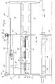
- the punches forming the upper cutting tools are each attached to the piston rods of the pressure medium piston cylinder units in a manner not shown. In operation, only the three pressure medium piston cylinder units are acted upon by pressure medium, which are each in the operating position, so that the cutting tools of the other three punching tool sets can be sharpened or exchanged.
- Fig. 2 From Fig. 2 it can be seen that only three punching tools and the associated three counter-tools are in the operating position and can punch 6 cut-outs from the three stacks supplied. If the tool sets in engagement are blunt, the motor 38 fastened on the cross member 24 is switched on, the pinion 39 of which meshes with the toothed rack 40 fastened to the side wall 30. As a result, the entire cassette 29 shifted in the direction of arrow A until the three punching tool sets on the left in FIG. 2 have moved out through the cutout 21 ′ and the three punching tool sets on the right in FIG. 2 have moved into the operating position. The blunt tool sets can then be sharpened or replaced without having to stop the shirt bag machine.
Applications Claiming Priority (2)
| Application Number | Priority Date | Filing Date | Title |
|---|---|---|---|
| DE3432385A DE3432385C2 (de) | 1984-09-03 | 1984-09-03 | Vorrichtung zum Stanzen von Stapeln aus flachen Werkstücken |
| DE3432385 | 1984-09-03 |
Publications (2)
| Publication Number | Publication Date |
|---|---|
| EP0175111A1 true EP0175111A1 (fr) | 1986-03-26 |
| EP0175111B1 EP0175111B1 (fr) | 1989-07-19 |
Family
ID=6244553
Family Applications (1)
| Application Number | Title | Priority Date | Filing Date |
|---|---|---|---|
| EP85109765A Expired EP0175111B1 (fr) | 1984-09-03 | 1985-08-02 | Appareil pour couper des piles de feuilles |
Country Status (7)
| Country | Link |
|---|---|
| US (1) | US4682524A (fr) |
| EP (1) | EP0175111B1 (fr) |
| JP (1) | JPS6165799A (fr) |
| CA (1) | CA1256015A (fr) |
| DE (1) | DE3432385C2 (fr) |
| DK (1) | DK399585A (fr) |
| ES (1) | ES8701012A1 (fr) |
Cited By (2)
| Publication number | Priority date | Publication date | Assignee | Title |
|---|---|---|---|---|
| EP0271229A1 (fr) * | 1986-11-13 | 1988-06-15 | Drg (Uk) Limited | Dispositif pour couper des bandes |
| WO2000018550A1 (fr) * | 1998-09-29 | 2000-04-06 | Febus S.R.L. | Machine de decoupage a l'emporte-piece |
Families Citing this family (11)
| Publication number | Priority date | Publication date | Assignee | Title |
|---|---|---|---|---|
| DE8506331U1 (de) * | 1985-03-05 | 1985-05-23 | Aktiebolaget Best Matic, Ronneby | Vorrichtung zur Bearbeitung nichtmetallischer Werkstoffe mit Hilfe eines Flüssigkeitsstrahl-Schneidwerkzeuges |
| DE3628620A1 (de) * | 1986-08-22 | 1987-01-29 | Burghart Konstruktionen Fa | Stanze fuer kartonagen und aehnliche materialien, mit horizontal beweglicher unterer stanzplatte |
| JPH0215294U (fr) * | 1988-07-06 | 1990-01-30 | ||
| US5216963A (en) * | 1988-10-17 | 1993-06-08 | Arkansas Technologies, Inc. | Arrangement for cutting slugs of unfired brick |
| US5088181A (en) * | 1990-10-09 | 1992-02-18 | The Boeing Company | Sheet metal part machining system |
| DE19914430A1 (de) * | 1999-03-30 | 2000-10-26 | Cww Gerko Akustik Gmbh & Co Kg | Schneidpresse |
| US6484387B1 (en) | 2000-06-07 | 2002-11-26 | L. H. Carbide Corporation | Progressive stamping die assembly having transversely movable die station and method of manufacturing a stack of laminae therewith |
| NL1019933C2 (nl) * | 2002-02-08 | 2003-08-11 | Fountain Tech Bv | Transportstans. |
| US6877413B1 (en) * | 2003-09-30 | 2005-04-12 | Cheng Tien Int'l Corp. | Slideable hole punch |
| DE102004006631A1 (de) * | 2003-10-11 | 2005-05-19 | Manfred Zimmermann | Vorrichtung und Verfahren zum Herstellen von Canape |
| CN109719769A (zh) * | 2018-12-03 | 2019-05-07 | 惠州市成泰自动化科技有限公司 | 智能屏幕保护膜切割设备 |
Citations (7)
| Publication number | Priority date | Publication date | Assignee | Title |
|---|---|---|---|---|
| DE2131397A1 (de) * | 1971-06-24 | 1973-01-11 | Manco Mfg Co | Werkzeug fuer metallverformungsvorrichtung |
| FR2262568A1 (fr) * | 1974-03-02 | 1975-09-26 | Sundwiger Eisen Maschinen | |
| DE2522654A1 (de) * | 1975-05-22 | 1976-12-09 | Schmitz Walzmasch | Wechselvorrichtung fuer kreismesserscheren zum laengsteilen von metallband |
| FR2420426A1 (fr) * | 1978-03-22 | 1979-10-19 | Chambon Machines | Imprimeuse rotative a plusieurs couleurs et a format variable |
| FR2451265A1 (fr) * | 1979-03-15 | 1980-10-10 | Biggar Frank | Dispositif d'impression a changement rapide |
| DE2915689A1 (de) * | 1979-04-18 | 1980-10-23 | Windmoeller & Hoelscher | Vorrichtung zur lagerichtigen abgabe von von einer materialbahn abgetrennten abschnitten |
| DE3331069A1 (de) * | 1983-08-29 | 1985-03-14 | Windmöller & Hölscher, 4540 Lengerich | Verfahren und vorrichtung zum aufheben der verblockung gestanzter beutelstapel |
Family Cites Families (6)
| Publication number | Priority date | Publication date | Assignee | Title |
|---|---|---|---|---|
| US3225686A (en) * | 1963-08-30 | 1965-12-28 | Minster Machine Co | Press with sliding bolster and die clamp |
| BE665204A (fr) * | 1964-06-16 | 1900-01-01 | ||
| US3448645A (en) * | 1966-08-11 | 1969-06-10 | Cincinnati Shaper Co | Numerically controlled punching machine and method |
| DE2235556A1 (de) * | 1972-07-20 | 1974-01-31 | Schubert & Salzer Maschinen | Vorrichtung zum zuschneiden textiler stoffbahnen |
| JPS5340790Y2 (fr) * | 1974-12-26 | 1978-10-02 | ||
| US4475424A (en) * | 1980-12-15 | 1984-10-09 | Amada Company, Limited | Blanking apparatus |
-
1984
- 1984-09-03 DE DE3432385A patent/DE3432385C2/de not_active Expired
-
1985
- 1985-08-02 EP EP85109765A patent/EP0175111B1/fr not_active Expired
- 1985-08-23 CA CA000489288A patent/CA1256015A/fr not_active Expired
- 1985-08-26 US US06/769,330 patent/US4682524A/en not_active Expired - Fee Related
- 1985-09-02 ES ES546657A patent/ES8701012A1/es not_active Expired
- 1985-09-02 JP JP60193689A patent/JPS6165799A/ja active Pending
- 1985-09-02 DK DK399585A patent/DK399585A/da not_active Application Discontinuation
Patent Citations (7)
| Publication number | Priority date | Publication date | Assignee | Title |
|---|---|---|---|---|
| DE2131397A1 (de) * | 1971-06-24 | 1973-01-11 | Manco Mfg Co | Werkzeug fuer metallverformungsvorrichtung |
| FR2262568A1 (fr) * | 1974-03-02 | 1975-09-26 | Sundwiger Eisen Maschinen | |
| DE2522654A1 (de) * | 1975-05-22 | 1976-12-09 | Schmitz Walzmasch | Wechselvorrichtung fuer kreismesserscheren zum laengsteilen von metallband |
| FR2420426A1 (fr) * | 1978-03-22 | 1979-10-19 | Chambon Machines | Imprimeuse rotative a plusieurs couleurs et a format variable |
| FR2451265A1 (fr) * | 1979-03-15 | 1980-10-10 | Biggar Frank | Dispositif d'impression a changement rapide |
| DE2915689A1 (de) * | 1979-04-18 | 1980-10-23 | Windmoeller & Hoelscher | Vorrichtung zur lagerichtigen abgabe von von einer materialbahn abgetrennten abschnitten |
| DE3331069A1 (de) * | 1983-08-29 | 1985-03-14 | Windmöller & Hölscher, 4540 Lengerich | Verfahren und vorrichtung zum aufheben der verblockung gestanzter beutelstapel |
Cited By (2)
| Publication number | Priority date | Publication date | Assignee | Title |
|---|---|---|---|---|
| EP0271229A1 (fr) * | 1986-11-13 | 1988-06-15 | Drg (Uk) Limited | Dispositif pour couper des bandes |
| WO2000018550A1 (fr) * | 1998-09-29 | 2000-04-06 | Febus S.R.L. | Machine de decoupage a l'emporte-piece |
Also Published As
| Publication number | Publication date |
|---|---|
| US4682524A (en) | 1987-07-28 |
| ES8701012A1 (es) | 1986-11-16 |
| DE3432385C2 (de) | 1986-07-17 |
| DK399585A (da) | 1986-03-04 |
| EP0175111B1 (fr) | 1989-07-19 |
| JPS6165799A (ja) | 1986-04-04 |
| DE3432385A1 (de) | 1986-03-13 |
| ES546657A0 (es) | 1986-11-16 |
| CA1256015A (fr) | 1989-06-20 |
| DK399585D0 (da) | 1985-09-02 |
Similar Documents
| Publication | Publication Date | Title |
|---|---|---|
| EP0187344B1 (fr) | Procédé et dispositif pour produire des piles individuelles composées d'une bande en accordéon | |
| DE3107495C2 (fr) | ||
| EP0175111B1 (fr) | Appareil pour couper des piles de feuilles | |
| CH659210A5 (de) | Drei-messer-schneidemaschine. | |
| EP0623542A1 (fr) | Dispositif pour empiler un chant de feuilles imprimées | |
| DE3038058A1 (de) | Einrichtung zum aufstapeln von flachen gegenstaenden,insbesondere von faltschachtel-zuschnitten | |
| DE3018987C2 (de) | Vorrichtung zur Herstellung von Blattstapeln | |
| DE2115161A1 (de) | Vorrichtung zur Herstellung von Handgriffen an thermoplastischen Tragebeuteln | |
| DE2909348C2 (fr) | ||
| DE3318314C2 (de) | Vorrichtung zum Trennen einzelner Nutzenstapel eines Stapels gestanzter Bögen | |
| DE4224010A1 (de) | Vorrichtung zum handhaben von bahn- oder bogenmaterial aus papier | |
| DE3505858C2 (fr) | ||
| EP0453806B1 (fr) | Installation pour empiler des pièces constituées d'éléments plats séparés ou de paquets desdits éléments plats | |
| EP0799780A2 (fr) | Dispositif de palettisation pour ramettes de papier | |
| DE2810518A1 (de) | Automatische buchbindemaschine | |
| DE4113479A1 (de) | Vorrichtung zum abstapeln von grossflaechigen, kontinuierlich anfallenden platten | |
| DE3534919A1 (de) | Beutel stapelnder und intermittierend bewegter foerderer | |
| EP1312568B1 (fr) | Assembleuse pour former des livres non reliés | |
| AT398547B (de) | Plattenaufteilanlage | |
| DE968333C (de) | Maschine zum Herstellen von Buechern | |
| EP0741101A2 (fr) | Méthode pour séparer une pile de cahiers dans un empileur et empileur pour la mise en oeuvre de cette méthode | |
| DE19821108C2 (de) | Gruppierungsvorrichtung für Packungen | |
| EP0064773A1 (fr) | Appareil pour confectionner et déposer des groupements de sacs en plastique | |
| DE3702747A1 (de) | Bandablaenger fuer naehautomaten | |
| EP0135734B1 (fr) | Procédé et dispositif pour supprimer le blocage de tas de sacs estampés |
Legal Events
| Date | Code | Title | Description |
|---|---|---|---|
| PUAI | Public reference made under article 153(3) epc to a published international application that has entered the european phase |
Free format text: ORIGINAL CODE: 0009012 |
|
| AK | Designated contracting states |
Kind code of ref document: A1 Designated state(s): BE FR GB IT |
|
| 17P | Request for examination filed |
Effective date: 19860926 |
|
| 17Q | First examination report despatched |
Effective date: 19880205 |
|
| GRAA | (expected) grant |
Free format text: ORIGINAL CODE: 0009210 |
|
| AK | Designated contracting states |
Kind code of ref document: B1 Designated state(s): BE FR GB IT |
|
| GBT | Gb: translation of ep patent filed (gb section 77(6)(a)/1977) | ||
| ET | Fr: translation filed | ||
| ITF | It: translation for a ep patent filed |
Owner name: BUGNION S.P.A. |
|
| PLBE | No opposition filed within time limit |
Free format text: ORIGINAL CODE: 0009261 |
|
| STAA | Information on the status of an ep patent application or granted ep patent |
Free format text: STATUS: NO OPPOSITION FILED WITHIN TIME LIMIT |
|
| PGFP | Annual fee paid to national office [announced via postgrant information from national office to epo] |
Ref country code: GB Payment date: 19900725 Year of fee payment: 6 |
|
| 26N | No opposition filed | ||
| PGFP | Annual fee paid to national office [announced via postgrant information from national office to epo] |
Ref country code: FR Payment date: 19900806 Year of fee payment: 6 |
|
| PG25 | Lapsed in a contracting state [announced via postgrant information from national office to epo] |
Ref country code: GB Effective date: 19910802 |
|
| PGFP | Annual fee paid to national office [announced via postgrant information from national office to epo] |
Ref country code: BE Payment date: 19910809 Year of fee payment: 7 |
|
| ITTA | It: last paid annual fee | ||
| GBPC | Gb: european patent ceased through non-payment of renewal fee | ||
| PG25 | Lapsed in a contracting state [announced via postgrant information from national office to epo] |
Ref country code: FR Effective date: 19920430 |
|
| REG | Reference to a national code |
Ref country code: FR Ref legal event code: ST |
|
| PG25 | Lapsed in a contracting state [announced via postgrant information from national office to epo] |
Ref country code: BE Effective date: 19920831 |
|
| BERE | Be: lapsed |
Owner name: WINDMOLLER & HOLSCHER Effective date: 19920831 |