EP0799780A2 - Dispositif de palettisation pour ramettes de papier - Google Patents
Dispositif de palettisation pour ramettes de papier Download PDFInfo
- Publication number
- EP0799780A2 EP0799780A2 EP97104935A EP97104935A EP0799780A2 EP 0799780 A2 EP0799780 A2 EP 0799780A2 EP 97104935 A EP97104935 A EP 97104935A EP 97104935 A EP97104935 A EP 97104935A EP 0799780 A2 EP0799780 A2 EP 0799780A2
- Authority
- EP
- European Patent Office
- Prior art keywords
- conveyor
- feed
- conveying direction
- loading
- feed conveyor
- Prior art date
- Legal status (The legal status is an assumption and is not a legal conclusion. Google has not performed a legal analysis and makes no representation as to the accuracy of the status listed.)
- Withdrawn
Links
Images


Classifications
-
- B—PERFORMING OPERATIONS; TRANSPORTING
- B65—CONVEYING; PACKING; STORING; HANDLING THIN OR FILAMENTARY MATERIAL
- B65G—TRANSPORT OR STORAGE DEVICES, e.g. CONVEYORS FOR LOADING OR TIPPING, SHOP CONVEYOR SYSTEMS OR PNEUMATIC TUBE CONVEYORS
- B65G57/00—Stacking of articles
- B65G57/02—Stacking of articles by adding to the top of the stack
- B65G57/11—Stacking of articles by adding to the top of the stack the articles being stacked by direct action of the feeding conveyor
Definitions
- the invention relates to a palletizing device, in particular for stacks of sheets of paper or the like, with a pallet table and a feed conveyor, the depositing end of which can be moved back and forth in the conveying direction above the pallet table.
- Ream packets in the present context are referred to as briefly packaged paper stacks which are formed from sheets of paper or similar material such as cardboard, plastic or the like which are stacked on top of one another.
- the term is intended to include stacks of sheets of any format, of any material and of any number also understood cartons, which in turn contain several packaged, banded or unpacked stacks of paper or the like.
- the ream parcels are usually cuboid and have a rectangular base area according to the size of the sheets they contain. For the purpose of storage or shipping, the parcels are sorted according to their Completion stored in one or more layers or layers on pallets, and other objects can also be palletized in this way.
- the German utility model G 94 18 577.8 U1 describes a palletizing device of the type specified at the outset.
- stacks of packaging blanks are stacked on pallets.
- a conveyor belt is provided, the width of which is equal to the pallet width.
- the stacks to be deposited are fed in rows on the conveyor belt in the side arrangement in which they are deposited on the pallet.
- the depositing takes place via the depositing end of the conveyor belt, which can be moved back and forth, first on an intermediate deposit, on which a complete layer of stacks is formed, which is finally deposited overall on the pallet positioned under the intermediate deposit.
- a multiple transfer of the stacks is therefore required, which increases the overall height of the device and increases the functional complexity.
- the invention is based on the object of proposing a further palletizing device of the type specified at the outset for ream stacks.
- At least the storage end of the feed conveyor can also be moved transversely to the conveying direction above the pallet table. This enables targeted placement of single-row packages in a row directly on the pallet in a specific arrangement and sequence.
- a preferred development of the invention consists in that the entire feed conveyor can be moved transversely to its conveying direction essentially over the entire width of the pallet. Due to this parallel transverse displacement of the feeder, the orientation of the parcels is always the same regardless of their location on the pallet.
- the feed conveyor consists of at least two partial conveyors which follow one another in the conveying direction, one of which conveys continuously as a transfer conveyor and the other runs intermittently as a loading conveyor and is stopped each time for depositing a package on the pallet enables a high conveying and depositing rate of the palletizing device.
- the design of the device according to claim 4 means a simple and rational construction.
- the use of belt conveyors as partial conveyors of the feed conveyor allows deflections of small diameter at the storage ends, whereby the storage height can be largely reduced.
- the formation of the storage end of the feed conveyor according to claim 6 has the advantage that the packages can also be inserted into narrow gaps between already stacked packages.
- the design of the device according to claim 7 increases its flexibility because the supply and storage of the packages can be optimally adapted to a wide variety of conditions.
- the alignment unit of the device according to the invention according to claim 8 ensures that the objects to be deposited always arrive correctly on the pallet in the desired orientation.
- Claims 9 to 12 represent further developments of the device according to the invention, which make it possible to transport the packages to be deposited on the pallet, preferably in one row one behind the other, from a stationary loading device in changing directions to the current position of the movable feeding end of the feed conveyor. This ensures that the packages essentially maintain an intended orientation, even if the conveying direction has a strong lateral component.
- the design of the device according to claim 13 ensures that the packages to be deposited on the pallet can be rotated into the orientation required for the storage.
- the features of claim 14 serve to store the packages on the pallet in several layers one above the other.
- the packages to be stacked are fed and deposited one after the other onto the pallet, which results in a high degree of flexibility because the orientation of the packages and their arrangement on the pallet are largely freely selectable.
- the packages can be stacked in different orientations, which results in a stable stacking configuration on the pallet.
- the mobility of the storage end of the loading conveyor in the conveying direction and the movability of the feed conveyor transversely to its conveying direction can be set on pallets of different sizes.
- the structure of the device according to the invention is structurally very simple and inexpensive.
- the storage height from the storage end of the loading conveyor to the surface of the pallet or the package layer already on the pallet can be selected to be very small, which enables the pallet to be loaded tightly.
- the device manages with a low overall height.
- the invention provides a palletizing device of high productivity, that is to say a high feed and deposit rate, with an exact and freely selectable placement arrangement of the packages on the pallet, which has relatively little design requirements.
- FIGS 1, 2 and 3 show an embodiment of the palletizing device according to the invention in three different views. Identical parts are provided with the same reference symbols in the figures.
- ream packets are stacks of sheets of paper, cardboard, plastic or the like which are stacked on top of one another and at least partially wrapped in wrapping material.
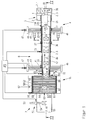
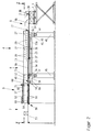
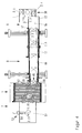
- the pallet 1 is on a height-adjustable pallet table 3, which can accommodate pallets of different sizes.
- the palletizing device shown as an exemplary embodiment has a feed conveyor 4, an intermediate conveyor 6 and a loading device 7.
- the feed conveyor 4 consists of two partial conveyors, a transfer conveyor 8 and a loading conveyor 9 adjoining it downstream.
- the transfer conveyor 8 has an essentially U-shaped conveyor trough 11 with a base plate 12 and vertical side walls 13.
- the conveyor run 8b of a conveyor belt 8a runs over the base plate 12 and is guided over rollers 14 and 16 mounted below the base plate 12 on both sides in the side cheeks 13 and a deflection roller 18 mounted on the discharge side end 17 of the transfer conveyor 8 on the front side of the base plate.
- the conveyor belt 8a is driven by a motor 19 in the conveying direction 21 via the roller 14.
- the loading conveyor 9 has an essentially U-shaped conveyor trough 22 with a base plate 23 and vertical side walls 24.
- the conveyor trough 22 is wider than the conveyor trough 11 and encompasses it from below, so that the base plate 23 of the loading conveyor 9 is at a short distance substantially parallel below the base plate 12 of the transfer conveyor 8 and its side walls 24 parallel outside the side walls 13 of the transfer conveyor 8 run.
- the bottom plate 23 of the loading conveyor 9 reaches laterally through portions of the side cheeks 13 of the conveyor trough 11 extending below the bottom plate 12, which is made possible by slots 26 running longitudinally in the side cheeks 13. In order to stabilize the sections 13a of the side cheeks 13 lying below the slots 26, the slots are bridged by means of brackets 27 encompassing the side cheeks 24 of the conveying trough 22 to the upper edge of the side cheeks 13.
- the conveyor trough 11 of the transfer conveyor 8 and the conveyor trough 22 of the loading conveyor 9 are connected to one another in a longitudinally displaceable manner.
- longitudinal guideways formed by parallel strips 28 are provided, in which guide rollers 29 mounted on the inside of the side walls 24 of the loading conveyor 9 are guided.
- the longitudinal displacement of the conveyor trough 22 is driven relative to the conveyor trough 11 by gear wheels 32 which are driven by a motor 31 and are mounted in the side walls 24 of the loading conveyor and engage with racks 33 running on the side walls 13 of the conveyor trough 11 of the transfer conveyor 8 and parallel to the guide strips 28 are.
- the bearing cap of the roller 36 was omitted on the right-hand side in order to make this rack 33 visible in the front view of FIG.
- the conveyor run 9b of a conveyor belt 9a runs over the base plate 23 of the conveyor trough 22, the rollers 34 and 36 mounted on both sides in the side walls 13 of the conveyor trough 11 below the base plates 12 and 23, one on the axis of the gear wheels 32 in the side walls 24 of the conveyor trough 22 mounted roller 37 and a roller 39 mounted on the storage end 38 of the loading conveyor 9 on the end face of the base plate 23.
- the base plate 23 is narrower than in the rear areas.
- the width of the base plate 23 corresponds approximately to the width of the conveyor belt 9a and, like this, is at most the same as the smallest edge length L (see FIG. 1) of the ream packages to be stacked. This makes it possible to insert the giant packs 2 in every orientation into narrow gaps between packets that have already been deposited.
- the conveyor belt 9a is driven by a motor 41 via the roller 34.
- the feed conveyor 4 together with the transfer conveyor 8 and the loading conveyor 9 is seated on cross slides 42 which are guided on cross guides 43 on cross members 44 by portal frames 46. With this arrangement, the entire feed conveyor 4 can be moved transversely to its conveying direction 21.
- the cross slides 42 are driven by motors 47 via chain, toothed belt or spindle drives, which are assumed to be known per se and therefore do not require any representation in the drawing and no further description.
- the carriages 42 and the transverse guides 43 are only shown schematically, since these are details familiar to the person skilled in the art.
- the transfer conveyor 8 is arranged stationary as seen in the conveying direction 21. Its feed end 48 and its discharge end 17 are fixed in relation to the conveying direction 21.
- the storage end 38 of the loading conveyor 9, on the other hand, is moved by moving the conveyor trough 22 in the conveying direction 21 above the pallet 1 or above the pallet table 3, the length of the conveyor run 9b of the conveyor belt 9a changing. These changes in length are compensated for by a corresponding change in the length of the return run of the conveyor belt in the belt loop which is formed between the stationary deflection roller 36 and the deflection roller 37 moved with the conveyor trough 22.
- the depositing end 38 of the loading conveyor 9 By moving the depositing end 38 of the loading conveyor 9 in the longitudinal or conveying direction 21 and back relative to the transfer conveyor 8 which is stationary in the conveying direction and by moving both conveyors 8 and 9 together on the portal frame 46 transversely to the conveying direction 21 of the feed conveyor 4, the depositing end 38 reaches each depositing position on the pallet 1.
- the travel paths of the conveyors in both directions are expediently dimensioned sufficiently so that pallets of different sizes can be loaded in this way without costly retrofitting and format adjustments.
- the diameter of the deflecting roller 18 at the discharge end 17 of the transfer conveyor 8 and the deflecting roller 39 at the depositing end 38 of the loading conveyor 9 are dimensioned as small as possible in order to keep the fall height of the packages 2 low during transfer and depositing. This makes it possible to place the packages on the pallet very close together.
- the motors 19 for driving the transfer conveyor 8, 41 for driving the loading conveyor 9, 31 for the longitudinal displacement of the storage end 38 and 47 for the transverse displacement of the entire feed conveyor 4 are connected to a common control arrangement 49 which controls the conveying speeds of the conveyor belts 8a and 9a and the longitudinal and transverse movements are coordinated with one another according to the respective circumstances.
- the conveyor belt 8a of the transfer conveyor 8 preferably rotates continuously in normal operation.
- the conveyor belt 9a of the loading conveyor 9 is driven as long as a package is moved on its conveyor run towards the storage end 38. To deposit a package, the conveyor belt 9a is stopped and the depositing end 38 is pulled back by moving the conveyor trough 22 with the base plate 23 under the package. This enables the parcels to be positioned very precisely on the pallet.
- the feeder 4 is loaded with packages 2 by means of the loading device 7 via the intermediate conveyor 6.
- the loading device 7 has a conveyor belt 51, to which an upstream packing machine (not shown) or a conveyor device delivers the packages 2 to be palletized one after the other.
- the conveyor belt 51 is assigned a rotating unit 52 which, in the case shown, is designed as a piston-cylinder unit 53 with a piston 54 which can be moved back and forth in a controlled manner into the movement path of the packages on the conveyor 51.
- the rotating unit 52 rotates the packages 2 moved on the conveyor 51, if necessary, into an orientation desired in each case for placement on the pallet.
- Figure 1 shows the rotating unit in its inactive, Figure 4 in its active position. The actuation of the rotating unit 52 can be controlled by the control arrangement 49.
- the intermediate conveyor 6 takes over the packages 2 in a defined, stationary transfer zone 56 and transports them in a variable direction depending on the transverse movement of the feed conveyor 4 to the end 48 of the feed conveyor. It has a first conveying means, which in the case shown is a roller conveyor 57 in the conveying direction 21 rollers 61 arranged one behind the other and jointly driven by a motor 59 via chains or toothed belts 58.
- the roller conveyor 57 transports the packages 2 in the conveying direction 21.
- the intermediate conveyor 6 is assigned a second conveying means in the form of two guide belts 62 rotating in parallel vertical planes to convey the packets 2 in directions changing according to the transverse position of the feed conveyor 4, the mutually facing conveying strands of which define a conveying path 63 of the packets on the roller conveyor 57 .
- the guide belts 62 run around rollers 64 and 66 mounted vertically on common supports 67.
- a common carrier 67 is provided separately for each of the guide rollers 64 and 66 of each guide belt 62.
- the guide belts are driven via the deflection rollers 66 by motors 71, which are controlled by the control arrangement 49.
- the carriers 67 are articulated on the feed conveyor 4 via connecting elements 68 so that they can pivot about the axes of the rollers 66.
- downstream deflection rollers 66 of the guide belts 62 are coupled to the feed end 48 of the transfer conveyor 8 of the feed conveyor 4, so that they always follow the transverse movements of the feed conveyor 4. In this way, the conveyor path 63 predetermined by the guide belts 62 always runs from the stationary transfer zone 56 to the displaceable feed end 48 of the feed conveyor 4.
- longitudinal guides 69 are provided in the conveying direction 21, in which the axes of the front deflection rollers 64 or the front ends of the carriers 62 are movably guided.
- an alignment unit 72 is assigned to the transfer conveyor 8. This has on both sides of the conveyor path of the packages towards and back to each other movable alignment plates 73 which align packages located on the conveyor belt 8a between the plates.
- the alignment plates 73 are actuated by piston-cylinder units 74.
- FIGS. 1, 4 and 5 The mode of operation of the device can be seen in FIGS. 1, 4 and 5, insofar as it is not already apparent from the previous description.
- the loading conveyor 9 is currently depositing the third package 2.3 of the first row of a layer of packages on the pallet 1. Below that is a complete layer of packages. In the first row of the second layer, the packages are oriented in the longitudinal direction. The next package 2.4 is also still oriented in the longitudinal direction, while the following packages, which are placed on the pallet in the next rows, are oriented transversely. The cross-oriented packets pass unhindered past the rotating unit 52 of the loading device 7, as shown in FIG. 1. FIG. 4 shows the placement of the package 2.4 in the first row on the far right on the pallet 1.
- the entire feed conveyor 4 has been moved further to the right from the position shown in FIG. 1, the deflection rollers 66 of the guide belts 62 of the intermediate conveyor 6 following it , so that the packages can continue via the intermediate conveyor to the feed end 48 of the feed conveyor.
- This also shows that the width of the loading conveyor 9 at its storage end 38 allows the packets 2 to be inserted into narrow positions via their narrow sides. Since after a few transversely oriented packages 2.5 to 2.10 the next packages are to be deposited again oriented in the longitudinal direction, the turning unit 52 is activated according to FIG. 4, so that the piston 54 engages in the conveying path of the packages and the package 2.11 and the following ones in the desired orientation turns.
- FIG. 4 Since after a few transversely oriented packages 2.5 to 2.10 the next packages are to be deposited again oriented in the longitudinal direction, the turning unit 52 is activated according to FIG. 4, so that the piston 54 engages in the conveying path of the packages and the package 2.11 and the following ones in the desired orientation turns.
- FIG. 5 shows the placement of the first transversely oriented packages 2.5 and 2.6 on the pallet 1.
- the offset orientation of the deposited packages in the longitudinal and transverse directions results in a very stable stack structure on the pallet.
- the storage of successive stacks 2 on the pallet 1 always requires only short movements of the loading conveyor 9 and the feed conveyor 4 in the longitudinal and transverse directions and in this way allows a high feed and deposit rate, which ensures high productivity of the device.
Landscapes
- Engineering & Computer Science (AREA)
- Mechanical Engineering (AREA)
- Attitude Control For Articles On Conveyors (AREA)
- Sheets, Magazines, And Separation Thereof (AREA)
- Stacking Of Articles And Auxiliary Devices (AREA)
Applications Claiming Priority (2)
| Application Number | Priority Date | Filing Date | Title |
|---|---|---|---|
| DE19613435 | 1996-04-04 | ||
| DE1996113435 DE19613435A1 (de) | 1996-04-04 | 1996-04-04 | Palettiervorrichtung für Riespakete |
Publications (2)
| Publication Number | Publication Date |
|---|---|
| EP0799780A2 true EP0799780A2 (fr) | 1997-10-08 |
| EP0799780A3 EP0799780A3 (fr) | 1998-08-05 |
Family
ID=7790428
Family Applications (1)
| Application Number | Title | Priority Date | Filing Date |
|---|---|---|---|
| EP97104935A Withdrawn EP0799780A3 (fr) | 1996-04-04 | 1997-03-22 | Dispositif de palettisation pour ramettes de papier |
Country Status (2)
| Country | Link |
|---|---|
| EP (1) | EP0799780A3 (fr) |
| DE (1) | DE19613435A1 (fr) |
Cited By (10)
| Publication number | Priority date | Publication date | Assignee | Title |
|---|---|---|---|---|
| WO2005080243A1 (fr) * | 2004-02-17 | 2005-09-01 | MSK-Verpackungs-Systeme Gesellschaft mit beschränkter Haftung | Dispositif et procede pour aligner un produit aisement deformable, au moins dans la zone des aretes exterieures inferieures, sur un support de transport |
| WO2009094681A1 (fr) | 2008-01-28 | 2009-08-06 | Tgw Mechanics Gmbh | Système de préparation de commandes et procédé de chargement d'un support de charge |
| EP2581330A1 (fr) * | 2011-10-10 | 2013-04-17 | Wipotec Wiege- und Positioniersysteme GmbH | Bande-navette |
| CH705735A1 (de) * | 2011-11-09 | 2013-05-15 | Busch Werke Ag | Vorrichtung zum kontrollierten Ablegen und Anordnen von Objekten. |
| US8534968B2 (en) | 2009-06-05 | 2013-09-17 | Georgia-Pacific Consumer Products Lp | Railcar distribution system and method for shipping product |
| US8572935B2 (en) | 2009-06-05 | 2013-11-05 | Georgia-Pacific Consumer Products Lp | Assemblage of and method of assembling reams of paper on a pallet |
| US9290316B2 (en) | 2009-07-02 | 2016-03-22 | Georgia-Pacific Consumer Products Lp | Assemblage of containers |
| CN106256693A (zh) * | 2015-06-19 | 2016-12-28 | 金东纸业(江苏)股份有限公司 | 层叠物品位移矫正装置 |
| EP3954635A1 (fr) | 2020-08-11 | 2022-02-16 | Stöcklin Logistik AG | Dispositif de chargement automatisé d'un porteur de charge doté d'unités de chargement formant un empilement de chargement et procédé correspondant |
| CN115872065A (zh) * | 2023-01-21 | 2023-03-31 | 山西大学 | 一种基于自动补位的球类运输用装载固定装置 |
Citations (4)
| Publication number | Priority date | Publication date | Assignee | Title |
|---|---|---|---|---|
| GB2010224A (en) * | 1977-12-12 | 1979-06-27 | Aluminum Co Of America | Automatic workpiece stacking device |
| GB2025354A (en) * | 1978-07-13 | 1980-01-23 | Monte Vite Sa L | Stacking apparatus |
| EP0275420A1 (fr) * | 1984-12-17 | 1988-07-27 | Nabisco Brands, Inc. | Dispositif de support pour barquette, spécialement pour un appareil de chargement automatique direct pour biscuits doux |
| US5501565A (en) * | 1992-08-12 | 1996-03-26 | Kabushiki Kaisha Shinkawa | Device for storing thin plate-form parts |
Family Cites Families (8)
| Publication number | Priority date | Publication date | Assignee | Title |
|---|---|---|---|---|
| AT376601B (de) * | 1983-10-14 | 1984-12-10 | Schelling & Co | Aufteilsaegeanlage |
| FI69036C (fi) * | 1983-12-30 | 1985-12-10 | Orfer Oy | Automatisk staplingsanlaeggning foer saeckar eller dylika |
| DE3411295A1 (de) * | 1984-03-27 | 1985-10-03 | Mohndruck Graphische Betriebe GmbH, 4830 Gütersloh | Palettiervorrichtung |
| US4624357A (en) * | 1984-06-25 | 1986-11-25 | Rotec Industries, Inc. | Vehicle-mounted extensible conveyor |
| DE3642123A1 (de) * | 1986-12-10 | 1988-06-16 | Thurne Gmbh | Einrichtung zum ablegen von scheibenfoermigen nahrungsmittelprodukten |
| DE9290067U1 (de) * | 1991-06-09 | 1994-01-20 | Krämer, Norbert, 64291 Darmstadt | Bandfördersystem für Schüttgut |
| DE4328461A1 (de) * | 1993-08-24 | 1995-03-02 | Meyer Herbert Gmbh Co Kg | Verfahren und Anordnung zum Fördern flächiger Werkstücke |
| DE9418577U1 (de) * | 1994-11-22 | 1995-01-05 | Icoma Packtechnik Gmbh, 77855 Achern | Palettiervorrichtung |
-
1996
- 1996-04-04 DE DE1996113435 patent/DE19613435A1/de not_active Withdrawn
-
1997
- 1997-03-22 EP EP97104935A patent/EP0799780A3/fr not_active Withdrawn
Patent Citations (4)
| Publication number | Priority date | Publication date | Assignee | Title |
|---|---|---|---|---|
| GB2010224A (en) * | 1977-12-12 | 1979-06-27 | Aluminum Co Of America | Automatic workpiece stacking device |
| GB2025354A (en) * | 1978-07-13 | 1980-01-23 | Monte Vite Sa L | Stacking apparatus |
| EP0275420A1 (fr) * | 1984-12-17 | 1988-07-27 | Nabisco Brands, Inc. | Dispositif de support pour barquette, spécialement pour un appareil de chargement automatique direct pour biscuits doux |
| US5501565A (en) * | 1992-08-12 | 1996-03-26 | Kabushiki Kaisha Shinkawa | Device for storing thin plate-form parts |
Cited By (17)
| Publication number | Priority date | Publication date | Assignee | Title |
|---|---|---|---|---|
| CN1842479B (zh) * | 2004-02-17 | 2011-06-08 | Msk包装系统股份有限公司 | 用于使在输送托板上容易变形的物品对准的装置和方法 |
| WO2005080243A1 (fr) * | 2004-02-17 | 2005-09-01 | MSK-Verpackungs-Systeme Gesellschaft mit beschränkter Haftung | Dispositif et procede pour aligner un produit aisement deformable, au moins dans la zone des aretes exterieures inferieures, sur un support de transport |
| US8708637B2 (en) | 2008-01-28 | 2014-04-29 | Tgw Mechanics Gmbh | Consignment system and method of loading a freight carrier |
| WO2009094681A1 (fr) | 2008-01-28 | 2009-08-06 | Tgw Mechanics Gmbh | Système de préparation de commandes et procédé de chargement d'un support de charge |
| US8534968B2 (en) | 2009-06-05 | 2013-09-17 | Georgia-Pacific Consumer Products Lp | Railcar distribution system and method for shipping product |
| US8572935B2 (en) | 2009-06-05 | 2013-11-05 | Georgia-Pacific Consumer Products Lp | Assemblage of and method of assembling reams of paper on a pallet |
| US9290316B2 (en) | 2009-07-02 | 2016-03-22 | Georgia-Pacific Consumer Products Lp | Assemblage of containers |
| EP2581330A1 (fr) * | 2011-10-10 | 2013-04-17 | Wipotec Wiege- und Positioniersysteme GmbH | Bande-navette |
| CH705735A1 (de) * | 2011-11-09 | 2013-05-15 | Busch Werke Ag | Vorrichtung zum kontrollierten Ablegen und Anordnen von Objekten. |
| EP2592027A1 (fr) * | 2011-11-09 | 2013-05-15 | Busch-Werke AG | Dispositif de dépôt et d'agencement contrôlés d'objets |
| CN106256693A (zh) * | 2015-06-19 | 2016-12-28 | 金东纸业(江苏)股份有限公司 | 层叠物品位移矫正装置 |
| CN106256693B (zh) * | 2015-06-19 | 2019-03-05 | 金东纸业(江苏)股份有限公司 | 层叠物品位移矫正装置 |
| EP3954635A1 (fr) | 2020-08-11 | 2022-02-16 | Stöcklin Logistik AG | Dispositif de chargement automatisé d'un porteur de charge doté d'unités de chargement formant un empilement de chargement et procédé correspondant |
| DE102020121097A1 (de) | 2020-08-11 | 2022-02-17 | Stöcklin Logistik Ag | Vorrichtung zur automatisierten Beladung eines Ladungsträgers mit einen Ladestapel bildenden Ladeeinheiten und Verfahren dazu |
| DE102020121097B4 (de) | 2020-08-11 | 2023-02-23 | Stöcklin Logistik Ag | Vorrichtung zur automatisierten Beladung eines Ladungsträgers mit einen Ladestapel bildenden Ladeeinheiten und Verfahren dazu |
| CN115872065A (zh) * | 2023-01-21 | 2023-03-31 | 山西大学 | 一种基于自动补位的球类运输用装载固定装置 |
| CN115872065B (zh) * | 2023-01-21 | 2023-05-09 | 山西大学 | 一种基于自动补位的球类运输用装载固定装置 |
Also Published As
| Publication number | Publication date |
|---|---|
| EP0799780A3 (fr) | 1998-08-05 |
| DE19613435A1 (de) | 1997-10-09 |
Similar Documents
| Publication | Publication Date | Title |
|---|---|---|
| DE4100769C2 (de) | Vorrichtung zum Fördern von Produkten in einer Verpackungsmaschine | |
| EP3372538B1 (fr) | Section de transport, procédé de réglage et/ou de positionnement d'au moins une bande transporteuse à l'intérieur d'une section de transport et installation d'emballage | |
| EP0298294B1 (fr) | Dispositif pour le groupement de paquets | |
| DE69618181T2 (de) | Verpackungsmaschine für sammelpackungen | |
| DE69410445T2 (de) | Vorrichtung zum verpacken von gegenständen in schachteln | |
| EP0095634B1 (fr) | Dispositif pour palettiser des marchandises | |
| EP0883565B1 (fr) | Systeme de transport et d'assemblage | |
| DE102008029497A1 (de) | Vorrichtung und Verfahren zum Zusammenstellen von Gebinden für eine Verpackungsmaschine | |
| EP0609669A1 (fr) | Dispositif d'alimentation d'un appareil palettiseur | |
| EP0799780A2 (fr) | Dispositif de palettisation pour ramettes de papier | |
| DE4419416A1 (de) | Verfahren und Vorrichtung zum Beschicken einer Packmaschine mit Packmaterialzuschnitten | |
| DE102012220479A1 (de) | Verfahren zum dynamischen Speichern und/oder Puffern von Artikeln und Förderstrecke mit einem Puffer- oder Speicherareal | |
| DE4017692C2 (fr) | ||
| EP3502017A1 (fr) | Dispositif et procédé de manipulation des portions des denrées alimentaires à l'aide d'un agencement rotatif | |
| DE4119514C2 (de) | Vorrichtung zum Transportieren von quaderförmigen Packungen von einer Verpackungsmaschine zu einer nachfolgenden Bearbeitungsmaschine | |
| DE69607698T2 (de) | Vorrichtung zum Be- und/oder Entladen von einem Behälter mit Stapeln von Packungen, insbesondere Eierkartons | |
| DE10225865A1 (de) | Vorrichtung zum Packen von flachen Gegenständen in Transportbehälter, insbesondere von flach gefalteten Faltschachteln in Umkartons | |
| DE3137676C2 (fr) | ||
| DE10225867A1 (de) | Vorrichtung zum Packen von flachen Gegenständen in Transportbehälter, insbesondere von flach gefalteten Faltschachteln in Umkartons | |
| WO2018149603A1 (fr) | Dispositif et procédé de distribution flexible d'emballages | |
| DE10110787A1 (de) | Verfahren und Vorrichtung zum Verpacken von länglichen Gegenständen | |
| EP1293453B1 (fr) | Dispositif pour la fabrication de couches palettisables | |
| DE10225646A1 (de) | Vorrichtung zum Packen von flachen Gegenständen in Transportbehälter, insbesondere von flach gefalteten Faltschachteln in Umkartons | |
| DE19821108C2 (de) | Gruppierungsvorrichtung für Packungen | |
| EP0896945A2 (fr) | Dispositif et procédé pour le traitement de matériel tel que des couches de piles en papier |
Legal Events
| Date | Code | Title | Description |
|---|---|---|---|
| PUAI | Public reference made under article 153(3) epc to a published international application that has entered the european phase |
Free format text: ORIGINAL CODE: 0009012 |
|
| AK | Designated contracting states |
Kind code of ref document: A2 Designated state(s): CH DE FI IT LI SE |
|
| PUAL | Search report despatched |
Free format text: ORIGINAL CODE: 0009013 |
|
| AK | Designated contracting states |
Kind code of ref document: A3 Designated state(s): CH DE FI IT LI SE |
|
| STAA | Information on the status of an ep patent application or granted ep patent |
Free format text: STATUS: THE APPLICATION IS DEEMED TO BE WITHDRAWN |
|
| 18D | Application deemed to be withdrawn |
Effective date: 19990206 |