EP0175111A1 - Apparatus for stamping piles of sheets - Google Patents
Apparatus for stamping piles of sheets Download PDFInfo
- Publication number
- EP0175111A1 EP0175111A1 EP85109765A EP85109765A EP0175111A1 EP 0175111 A1 EP0175111 A1 EP 0175111A1 EP 85109765 A EP85109765 A EP 85109765A EP 85109765 A EP85109765 A EP 85109765A EP 0175111 A1 EP0175111 A1 EP 0175111A1
- Authority
- EP
- European Patent Office
- Prior art keywords
- machine frame
- punching
- carriage
- frame
- punching tools
- Prior art date
- Legal status (The legal status is an assumption and is not a legal conclusion. Google has not performed a legal analysis and makes no representation as to the accuracy of the status listed.)
- Granted
Links
Images


Classifications
-
- B—PERFORMING OPERATIONS; TRANSPORTING
- B23—MACHINE TOOLS; METAL-WORKING NOT OTHERWISE PROVIDED FOR
- B23D—PLANING; SLOTTING; SHEARING; BROACHING; SAWING; FILING; SCRAPING; LIKE OPERATIONS FOR WORKING METAL BY REMOVING MATERIAL, NOT OTHERWISE PROVIDED FOR
- B23D35/00—Tools for shearing machines or shearing devices; Holders or chucks for shearing tools
- B23D35/008—Means for changing the cutting members
-
- Y—GENERAL TAGGING OF NEW TECHNOLOGICAL DEVELOPMENTS; GENERAL TAGGING OF CROSS-SECTIONAL TECHNOLOGIES SPANNING OVER SEVERAL SECTIONS OF THE IPC; TECHNICAL SUBJECTS COVERED BY FORMER USPC CROSS-REFERENCE ART COLLECTIONS [XRACs] AND DIGESTS
- Y10—TECHNICAL SUBJECTS COVERED BY FORMER USPC
- Y10S—TECHNICAL SUBJECTS COVERED BY FORMER USPC CROSS-REFERENCE ART COLLECTIONS [XRACs] AND DIGESTS
- Y10S83/00—Cutting
- Y10S83/929—Particular nature of work or product
- Y10S83/936—Cloth or leather
- Y10S83/939—Cloth or leather with work support
-
- Y—GENERAL TAGGING OF NEW TECHNOLOGICAL DEVELOPMENTS; GENERAL TAGGING OF CROSS-SECTIONAL TECHNOLOGIES SPANNING OVER SEVERAL SECTIONS OF THE IPC; TECHNICAL SUBJECTS COVERED BY FORMER USPC CROSS-REFERENCE ART COLLECTIONS [XRACs] AND DIGESTS
- Y10—TECHNICAL SUBJECTS COVERED BY FORMER USPC
- Y10T—TECHNICAL SUBJECTS COVERED BY FORMER US CLASSIFICATION
- Y10T83/00—Cutting
- Y10T83/202—With product handling means
- Y10T83/2092—Means to move, guide, or permit free fall or flight of product
- Y10T83/2183—Product mover including gripper means
-
- Y—GENERAL TAGGING OF NEW TECHNOLOGICAL DEVELOPMENTS; GENERAL TAGGING OF CROSS-SECTIONAL TECHNOLOGIES SPANNING OVER SEVERAL SECTIONS OF THE IPC; TECHNICAL SUBJECTS COVERED BY FORMER USPC CROSS-REFERENCE ART COLLECTIONS [XRACs] AND DIGESTS
- Y10—TECHNICAL SUBJECTS COVERED BY FORMER USPC
- Y10T—TECHNICAL SUBJECTS COVERED BY FORMER US CLASSIFICATION
- Y10T83/00—Cutting
- Y10T83/202—With product handling means
- Y10T83/2092—Means to move, guide, or permit free fall or flight of product
- Y10T83/2192—Endless conveyor
-
- Y—GENERAL TAGGING OF NEW TECHNOLOGICAL DEVELOPMENTS; GENERAL TAGGING OF CROSS-SECTIONAL TECHNOLOGIES SPANNING OVER SEVERAL SECTIONS OF THE IPC; TECHNICAL SUBJECTS COVERED BY FORMER USPC CROSS-REFERENCE ART COLLECTIONS [XRACs] AND DIGESTS
- Y10—TECHNICAL SUBJECTS COVERED BY FORMER USPC
- Y10T—TECHNICAL SUBJECTS COVERED BY FORMER US CLASSIFICATION
- Y10T83/00—Cutting
- Y10T83/444—Tool engages work during dwell of intermittent workfeed
- Y10T83/4501—Work feed means controlled by means mounted on tool or tool support
- Y10T83/4503—Such means drives the work feed means
- Y10T83/4506—Work feed means carried by tool or tool support
-
- Y—GENERAL TAGGING OF NEW TECHNOLOGICAL DEVELOPMENTS; GENERAL TAGGING OF CROSS-SECTIONAL TECHNOLOGIES SPANNING OVER SEVERAL SECTIONS OF THE IPC; TECHNICAL SUBJECTS COVERED BY FORMER USPC CROSS-REFERENCE ART COLLECTIONS [XRACs] AND DIGESTS
- Y10—TECHNICAL SUBJECTS COVERED BY FORMER USPC
- Y10T—TECHNICAL SUBJECTS COVERED BY FORMER US CLASSIFICATION
- Y10T83/00—Cutting
- Y10T83/869—Means to drive or to guide tool
- Y10T83/8727—Plural tools selectively engageable with single drive
-
- Y—GENERAL TAGGING OF NEW TECHNOLOGICAL DEVELOPMENTS; GENERAL TAGGING OF CROSS-SECTIONAL TECHNOLOGIES SPANNING OVER SEVERAL SECTIONS OF THE IPC; TECHNICAL SUBJECTS COVERED BY FORMER USPC CROSS-REFERENCE ART COLLECTIONS [XRACs] AND DIGESTS
- Y10—TECHNICAL SUBJECTS COVERED BY FORMER USPC
- Y10T—TECHNICAL SUBJECTS COVERED BY FORMER US CLASSIFICATION
- Y10T83/00—Cutting
- Y10T83/869—Means to drive or to guide tool
- Y10T83/8742—Tool pair positionable as a unit
- Y10T83/8743—Straight line positioning
-
- Y—GENERAL TAGGING OF NEW TECHNOLOGICAL DEVELOPMENTS; GENERAL TAGGING OF CROSS-SECTIONAL TECHNOLOGIES SPANNING OVER SEVERAL SECTIONS OF THE IPC; TECHNICAL SUBJECTS COVERED BY FORMER USPC CROSS-REFERENCE ART COLLECTIONS [XRACs] AND DIGESTS
- Y10—TECHNICAL SUBJECTS COVERED BY FORMER USPC
- Y10T—TECHNICAL SUBJECTS COVERED BY FORMER US CLASSIFICATION
- Y10T83/00—Cutting
- Y10T83/869—Means to drive or to guide tool
- Y10T83/8748—Tool displaceable to inactive position [e.g., for work loading]
Definitions
- the invention relates to a device for punching stacks of flat workpieces, preferably of shirt cutouts from stacked, with side gussets and head and bottom weld seams provided tube sections made of thermoplastic material for the production of shirt bags, with a set of punching tools stored in a machine frame, the stamp with a Provide this upward and downward moving drive and the cutting plate is arranged fixed to the frame, and with a conveyor device which intermittently conveys and removes the stacks between the punching tools.
- the object of the invention is therefore to improve a device according to the preamble of patent claim such that the die sets which have become blunt no longer result in any appreciable machine downtimes which interrupt production.
- this object is achieved in that at least two sets of punching tools with their associated drives are arranged in a row in a carriage which can be moved back and forth across the conveying direction in the machine frame and can be locked in two operating positions in the machine frame, in each of which at least one Set of punching tools has moved out of the side of the machine frame
- the number of punching tool sets that process the stack is doubled, so that half of the punching tool sets is in their operating position, while the other half of the punching tool sets is shifted into its rest position, preferably outside the machine frame, so that the punches and Cutting plates of these punching tool sets can be reground or exchanged.
- the slide expediently consists of a frame-like construction with cross members for the upper and lower punching tools, which is supported on rollers mounted in the machine frame, the side walls of the machine frame being provided with windows from which the slide can be moved out.
- a welding and separating device 1 which works in the so-called triple benefit, welds three tube sections, which are provided with head and bottom weld seams, from three parallel lying flat and side gusseted tube tracks in each cycle.
- the device is mainly described only on the basis of a so-called benefit, since the corresponding devices of the other benefits are identical.
- the hose sections provided with head and bottom weld seams first reach a lower suction conveyor belt 3 and are transferred from this to an upper suction conveyor belt 4.
- an upper suction conveyor belt 4 Below the end of this upper suction belt conveyor 4 on the delivery side there is a stacking table 5 onto which the individual bags 2 are dropped and stacked there.
- the gripper tongs 7 consist of lower legs 9 firmly connected to a cross member 8 and of upper legs 10 which are fastened to a rotatable shaft 11.
- the shaft 11 is mounted in holders 12, the latter being screwed to the cross member 8.
- an endless toothed belt 13 or 14 engages, each of which wraps around two deflection rollers 15, 16 and 17, 18, at least one of which is reversibly drivable.
- the deflection rollers 15 - 18 are mounted in two side rails 19 and 20.
- Each side rail is permanently welded to a frame side wall 21 or 22, the latter being connected to one another by cross members 23 and 24 and by a shaft 25.
- the punches forming the upper cutting tools are each attached to the piston rods of the pressure medium piston cylinder units in a manner not shown. In operation, only the three pressure medium piston cylinder units are acted upon by pressure medium, which are each in the operating position, so that the cutting tools of the other three punching tool sets can be sharpened or exchanged.
- Fig. 2 From Fig. 2 it can be seen that only three punching tools and the associated three counter-tools are in the operating position and can punch 6 cut-outs from the three stacks supplied. If the tool sets in engagement are blunt, the motor 38 fastened on the cross member 24 is switched on, the pinion 39 of which meshes with the toothed rack 40 fastened to the side wall 30. As a result, the entire cassette 29 shifted in the direction of arrow A until the three punching tool sets on the left in FIG. 2 have moved out through the cutout 21 ′ and the three punching tool sets on the right in FIG. 2 have moved into the operating position. The blunt tool sets can then be sharpened or replaced without having to stop the shirt bag machine.
Abstract
Eine Vorrichtung zum Stanzen von Stapeln (6) aus flachen Werkstücken, weist einen in einem Maschinengestell gelagerten Satz von Stanzwerkzeugen (36) auf, deren Stempel mit einem diesen aufwärts- und abwärtsbewegenden Antrieb (37) versehen und deren Schneidplatte gestellfest angeordnet ist. Um stumpfgewordene Stanzwerkzeugsätze (36) schnell und einfach austauschen zu können, sind mindestens zwei Sätze von Stanzwerkzeugen (36) mit ihren zugehörigen Antrieben (37) in einer Reihe in einem im Maschinengestell quer zur Förderrichtung hin- und herverschieblich geführten Schlitten (29) angeordnet, der in seinen zwei Betriebsstellungen im Maschinengestell arretierbar ist.A device for punching stacks (6) from flat workpieces has a set of punching tools (36) mounted in a machine frame, the punches of which are provided with a drive (37) which moves them up and down and the cutting plate is arranged fixed to the frame. In order to be able to replace punching tool sets (36) which have become blunt quickly and easily, at least two sets of punching tools (36) with their associated drives (37) are arranged in a row in a carriage (29) which can be moved back and forth across the conveying direction in the machine frame, which can be locked in its two operating positions in the machine frame.
Description
Die Erfindung betrifft eine Vorrichtung zum Stanzen von Stapeln aus flachen Werkstücken, vorzugsweise von Hemdchenausschnitten aus gestapelten, mit Seitenfalten und Kopf- und Bodenschweißnähten versehenen Schlauchabschnitten aus thermoplastischem Material zur Herstellung von Hemdchenbeuteln, mit einem in einem Maschinengestell gelagerten Satz von Stanzwerkzeugen, deren Stempel mit einem diesen aufwärts und abwärts bewegenden Antrieb versehen und deren Schneidplatte gestellfest angeordnet ist, und mit einer die Stapel intermittierend zwischen die Stanzwerkzeuge fördernden und abfördernden Fördereinrichtung.The invention relates to a device for punching stacks of flat workpieces, preferably of shirt cutouts from stacked, with side gussets and head and bottom weld seams provided tube sections made of thermoplastic material for the production of shirt bags, with a set of punching tools stored in a machine frame, the stamp with a Provide this upward and downward moving drive and the cutting plate is arranged fixed to the frame, and with a conveyor device which intermittently conveys and removes the stacks between the punching tools.
Bei aus der DE-OS 29 15 689 und 33.31.069 bekannten Vorrichtungen dieser Art zur Herstellung von Hemdchenbeuteln werden die Stanzwerkzeuge verhältnismäßig schnell stumpf, was ein häufiges Nachschleifen bzw. Auswechseln der stumpfen Stanzwerkzeugsätze bedingt und damit längere Maschinenstillstände zur Folge hat.In from DE-OS 29 15 689 and 33.31. 0 69 known devices of this type for the production of camisole bags, the punching tools become blunt relatively quickly, which requires frequent regrinding or replacement of the blunt punching tool sets and thus results in longer machine downtimes.
Aufgabe der Erfindung ist es daher, eine Vorrichtung nach dem Oberbegriff des Patentanspruchs derart zu verbessern, daß durch die stumpfgewordenen Stanzwerkzeugsätze keine nennenswerten die Produktion unterbrechenden Maschinenstillstände mehr entstehen.The object of the invention is therefore to improve a device according to the preamble of patent claim such that the die sets which have become blunt no longer result in any appreciable machine downtimes which interrupt production.
Erfindungsgemäß wird diese Aufgabe dadurch gelöst, daß mindestens zwei Sätze von Stanzwerkzeugen mit ihren zugehörigen Antrieben in einer Reihe in einem im Maschinengestell quer zur Förderrichtung hin- und herverschieblich geführten Schlitten angeordnet sind, der in zwei Betriebsstellungen im Maschinengestell arretierbar ist, in denen jeweils mindestens ein Satz der Stanzwerkzeuge seitlich aus dem Maschinengestell herausgefahren ist. Bei der erfindungsgemäßen Vorrichtung ist die Anzahl der die Stapel bearbeitenden Stanzwerkzeugsätze verdoppelt, so daß sich jeweils die Hälfte der Stanzwerkzeugsätze in ihrer Betriebsstellung befindet, während die andere Hälfte der Stanzwerkzeugsätze in ihre Ruhestellung, vorzugsweise außerhalb des Maschinengestells, verschoben ist, so daß die Stempel und Schneidplatten dieser Stanzwerkzeugsätze nachgeschliffen oder ausgetauscht werden können. Um einen geschärften oder ausgetauschten Werkzeugsatz in die Betriebsstellung zu bringen, ist es lediglich erforderlich, den Schlitten um die entsprechende Strecke quer zu verschieben. Diese Verschiebung erfolgt in der Zeit, in der ein neues Paket gebildet wird, so daß keine Betriebs unterbrechung erforderlich ist. Der erhöhte Aufwand, der durch die Verdoppelung der Stanzwerkzeugsätze entsteht, ist im Verhältnis zum Gesamtwert der Maschine nur gering,According to the invention, this object is achieved in that at least two sets of punching tools with their associated drives are arranged in a row in a carriage which can be moved back and forth across the conveying direction in the machine frame and can be locked in two operating positions in the machine frame, in each of which at least one Set of punching tools has moved out of the side of the machine frame In the device according to the invention, the number of punching tool sets that process the stack is doubled, so that half of the punching tool sets is in their operating position, while the other half of the punching tool sets is shifted into its rest position, preferably outside the machine frame, so that the punches and Cutting plates of these punching tool sets can be reground or exchanged. In order to bring a sharpened or replaced tool set into the operating position, it is only necessary to move the slide across the corresponding distance. This shift takes place in the time in which a new packet is formed, so that no interruption in operation is required. The increased effort that results from doubling the punching tool sets is only slight in relation to the total value of the machine,
so daß sich die entsprechenden zusätzlichen Kosten durch den Wegfall der sonst notwendigen Betriebsunterbrechungen schnell amortisieren.so that the corresponding additional costs are quickly amortized by the elimination of the otherwise necessary business interruptions.
Zweckmäßigerweise besteht der Schlitten aus einer rahmenartigen Konstruktion mit Querträgern für die oberen und unteren Stanzwerkzeuge, der auf im Maschinengestell gelagerten Rollen abgestützt ist, wobei die Seitenwände des Maschinengestells mit Fenstern versehen sind, aus denen der Schlitten herausfahrbar ist.The slide expediently consists of a frame-like construction with cross members for the upper and lower punching tools, which is supported on rollers mounted in the machine frame, the side walls of the machine frame being provided with windows from which the slide can be moved out.
Weitere vorteilhafte Ausgestaltungen der Erfindung sind Gegenstand der Unteransprüche.Further advantageous embodiments of the invention are the subject of the dependent claims.
Ein Ausführungsbeispiel der Erfindung wird nachstehend anhand der Zeichnung näher erläutert. In dieser zeigt
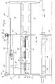
- Fig. 1 eine Seitenansicht der Vorrichtung zum Bilden von Stapeln aus mit Kopf- und Bodenschweißnähten versehenen Schlauchabschnitten und zum Stanzen und Fördern dieser Stapel in schematischer Seitenansicht,
- Fig. 2 eine Vorderansicht der Stanzeinrichtung nach Fig. 1 in vergrößerter Darstellung und
- Fig. 3 eine Seitenansicht der Stanzeinrichtung nach Fig. 2.
- 1 is a side view of the device for forming stacks from tube sections provided with head and bottom weld seams and for punching and conveying these stacks in a schematic side view,
- Fig. 2 is a front view of the punching device of FIG. 1 in an enlarged view and
- 3 shows a side view of the punching device according to FIG. 2.
Eine im sogenannten Dreifachnutzen arbeitende Schweiß- und Trenneinrichtung 1 schweißt jeweils von drei parallel zueinander geförderten flachliegenden und mit Seitenfalten versehenen Schlauchbahnen in jedem Takt drei Schlauchabschnitte ab, die mit Kopf- und Bodenschweißnähten versehen sind.A welding and separating
Im folgenden wird die Vorrichtung hauptsächlich nur anhand eines sogenannten Nutzens beschrieben, da die entsprechenden Einrichtungen der anderen Nutzen identisch sind.In the following, the device is mainly described only on the basis of a so-called benefit, since the corresponding devices of the other benefits are identical.
Die mit Kopf- und Bodenschweißnähten versehenen Schlauchabschnitte gelangen zunächst auf ein unteres Saugförderband 3 und werden von diesem an ein oberes Saugförderband 4 übergeben. Unterhalb des abgabeseitigen Endes dieses oberen Saugbandförderers 4 befindet sich ein Stapeltisch 5, auf den die einzelnen Beutel 2 abgeworfen und dort gestapelt werden. Sobald ein Stapel 6 mit der gewünschten Beutelzahl gebildet ist, wird dieser an seinem in Förderrichtung gesehen vorderen Ende von Greiferzangen 7 festgeklemmt und unter eine Stanze 8' gezogen, die die Ausschnitte zur Herstellung von Hemdchenbeuteln ausstanzt. Die Greiferzangen 7 bestehen aus unteren mit einem Querträger 8 fest verbundenen Schenkeln 9 und aus oberen Schenkeln 10, die an einer verdrehbaren Welle 11 befestigt sind. Die Welle 11 ist in Haltern 12 gelagert, wobei letztere mit dem Querträger 8 verschraubt sind.The hose sections provided with head and bottom weld seams first reach a lower suction conveyor belt 3 and are transferred from this to an upper
An beide Enden des Querträgers 8 greift jeweils ein Endloszahnriemen 13 bzw. 14 an, die je zwei Umlenkrollen 15, 16 bzw. 17, 18 umschlingen, von denen zumindest eine reversierend antreibbar ist. Die Umlenkrollen 15 - 18 sind in zwei Seitenholmen 19 und 20 gelagert. Je ein Seitenholm ist fest mit je einer Rahmenseitenwand 21 bzw. 22 verschweißt, wobei letztere miteinander durch Quertraversen 23 und 24 sowie durch eine Welle 25 verbunden ist.At both ends of the
Aus den Fig. 1 und 2 ist zu erkennen, daß die Rahmenseitenwände 21 und 22 fensterartige Ausschnitte 21' und 22' aufweisen. Auf die unteren Begrenzungen der Ausschnitte 21' und 22' sind seitliche Träger 26 und 27 aufgelegt und befestigt, die die beiden Rahmenseitenwände 21 und 22 miteinander verbinden und die auf den Rahmenseitenwänden nach außen um ein geringes Maß vorstehen. An den Trägern 26 und 27 sind mehrere Tragrollen 28 drehbar gelagert, auf denen eine Kassette 29 verschiebbar aufruht. Die Kassette 29 besteht aus oberen und unteren Seitenwänden 30 und 31 sowie aus diese miteinander verbindenden Stirnplatten 32 und 33. Sowohl mit den Stirnplatten als auch mit den Seitenwänden sind zwei parallel und mit Abstand zueinander verlaufende Stützplatten 34 und 35 verschweißt, wobei die obere 34 insgesamt sechs Stanzwerkzeuge 36 und die untere 35 die entsprechenden Gegenwerkzeuge trägt. Der Einfachheit halber ist nur eine einem Stanzwerkzeug 36 zugeordnete Kolbenzylindereinheit 37 dargestellt.1 and 2 that the
Die die oberen Schneidwerkzeuge bildenden Stempel sind in nicht dargestellter Weise jeweils an den Kolbenstangen der Druckmittelkolbenzylindereinheiten befestigt. Im Betrieb werden nur die drei Druckmittelkolbenzylindereinheiten mit Druckmittel beaufschlagt, die sich jeweils in der Betriebsstellung befinden, so daß die Schneidwerkzeuge der anderen drei Stanzwerkzeugsätze geschärft oder ausgetauscht werden können.The punches forming the upper cutting tools are each attached to the piston rods of the pressure medium piston cylinder units in a manner not shown. In operation, only the three pressure medium piston cylinder units are acted upon by pressure medium, which are each in the operating position, so that the cutting tools of the other three punching tool sets can be sharpened or exchanged.
Aus der Fig. 2 ist zu erkennen, daß nur drei Stanzwerkzeuge und die zugehörigen drei Gegenwerkzeuge in Betriebsstellung sind und aus den drei zugeführten Stapeln 6 Hemdchenbeutelausschnitte ausstanzen können. Sind die im Eingriff befindlichen Werkzeugsätze stumpf, wird der auf der Traverse 24 befestigte Motor 38 eingeschaltet, dessen Ritzel 39 mit der an der Seitenwand 30 befestigten Zahnstange 40 kämmt. Hierdurch wird die gesamte Kassette 29 in Pfeilrichtung A so weit verschoben, bis die drei in Fig. 2 linken Stanzwerkzeugsätze durch den Ausschnitt 21' heraus und die drei in Fig. 2 rechten Stanzwerkzeugsätze in Betriebsstellung gefahren sind. Die stumpfen Werkzeugsätze können dann geschärft bzw. ausgetauscht werden, ohne die Hemdchenbeutelmaschine stillsetzen zu müssen.From Fig. 2 it can be seen that only three punching tools and the associated three counter-tools are in the operating position and can punch 6 cut-outs from the three stacks supplied. If the tool sets in engagement are blunt, the
Damit nun die Kassette 29 in der gewünschten Stellung arretiert ist, sind auf die Enden der Welle 25 Handhebel 41 aufgesetzt, so daß die Welle 25 verdreht werden kann. Damit werden gleichzeitig auch die auf der Welle befestigten Exzenterbüchsen 42 verdreht, so daß die Druckstücke 43, in denen die Exzenterbüchsen 42 gelagert sind, von oben auf die Kassette 29 gepreßt werden, so daß diese zwischen den Druckstükken und den Tragrollen 28 verklemmt wird.So that the
Claims (5)
Applications Claiming Priority (2)
| Application Number | Priority Date | Filing Date | Title |
|---|---|---|---|
| DE3432385 | 1984-09-03 | ||
| DE3432385A DE3432385C2 (en) | 1984-09-03 | 1984-09-03 | Device for punching stacks from flat workpieces |
Publications (2)
| Publication Number | Publication Date |
|---|---|
| EP0175111A1 true EP0175111A1 (en) | 1986-03-26 |
| EP0175111B1 EP0175111B1 (en) | 1989-07-19 |
Family
ID=6244553
Family Applications (1)
| Application Number | Title | Priority Date | Filing Date |
|---|---|---|---|
| EP85109765A Expired EP0175111B1 (en) | 1984-09-03 | 1985-08-02 | Apparatus for stamping piles of sheets |
Country Status (7)
| Country | Link |
|---|---|
| US (1) | US4682524A (en) |
| EP (1) | EP0175111B1 (en) |
| JP (1) | JPS6165799A (en) |
| CA (1) | CA1256015A (en) |
| DE (1) | DE3432385C2 (en) |
| DK (1) | DK399585A (en) |
| ES (1) | ES8701012A1 (en) |
Cited By (2)
| Publication number | Priority date | Publication date | Assignee | Title |
|---|---|---|---|---|
| EP0271229A1 (en) * | 1986-11-13 | 1988-06-15 | Drg (Uk) Limited | Cutting webs of material |
| WO2000018550A1 (en) * | 1998-09-29 | 2000-04-06 | Febus S.R.L. | Die cutting machine |
Families Citing this family (11)
| Publication number | Priority date | Publication date | Assignee | Title |
|---|---|---|---|---|
| DE8506331U1 (en) * | 1985-03-05 | 1985-05-23 | Aktiebolaget Best Matic, Ronneby | Device for processing non-metallic materials with the aid of a liquid jet cutting tool |
| DE3628620A1 (en) * | 1986-08-22 | 1987-01-29 | Burghart Konstruktionen Fa | Punch for cardboard and similar materials, with a lower punching plate which is horizontally moveable |
| JPH0215294U (en) * | 1988-07-06 | 1990-01-30 | ||
| US5216963A (en) * | 1988-10-17 | 1993-06-08 | Arkansas Technologies, Inc. | Arrangement for cutting slugs of unfired brick |
| US5088181A (en) * | 1990-10-09 | 1992-02-18 | The Boeing Company | Sheet metal part machining system |
| DE19914430A1 (en) * | 1999-03-30 | 2000-10-26 | Cww Gerko Akustik Gmbh & Co Kg | Cutting press |
| US6484387B1 (en) | 2000-06-07 | 2002-11-26 | L. H. Carbide Corporation | Progressive stamping die assembly having transversely movable die station and method of manufacturing a stack of laminae therewith |
| NL1019933C2 (en) * | 2002-02-08 | 2003-08-11 | Fountain Tech Bv | Transport die. |
| US6877413B1 (en) * | 2003-09-30 | 2005-04-12 | Cheng Tien Int'l Corp. | Slideable hole punch |
| DE102004006631A1 (en) * | 2003-10-11 | 2005-05-19 | Manfred Zimmermann | Apparatus and method for manufacturing canape |
| CN109719769A (en) * | 2018-12-03 | 2019-05-07 | 惠州市成泰自动化科技有限公司 | Intelligent screen protection film cutting equipment |
Citations (7)
| Publication number | Priority date | Publication date | Assignee | Title |
|---|---|---|---|---|
| DE2131397A1 (en) * | 1971-06-24 | 1973-01-11 | Manco Mfg Co | Metal-working machine tool - designed for swift tool change in multi-purpose systems for shearing,notching,bending,punchin |
| FR2262568A1 (en) * | 1974-03-02 | 1975-09-26 | Sundwiger Eisen Maschinen | |
| DE2522654A1 (en) * | 1975-05-22 | 1976-12-09 | Schmitz Walzmasch | Metal strip cutting circular shears - has changeover device formed by carriages on rails carrying shears, crossways to strip |
| FR2420426A1 (en) * | 1978-03-22 | 1979-10-19 | Chambon Machines | Variable format as multicolour printer - has counter rollers mounted in adjustable frame to tangentially contact blanket rollers |
| FR2451265A1 (en) * | 1979-03-15 | 1980-10-10 | Biggar Frank | QUICK CHANGE PRINTING DEVICE |
| DE2915689A1 (en) * | 1979-04-18 | 1980-10-23 | Windmoeller & Hoelscher | Ancillary conveyors for locating successive moving panels - of tubular film for positional integration of film cutting and bag making mechanisms |
| DE3331069A1 (en) * | 1983-08-29 | 1985-03-14 | Windmöller & Hölscher, 4540 Lengerich | METHOD AND DEVICE FOR UNLOCKING PUNCHED PACKS OF BAGS |
Family Cites Families (6)
| Publication number | Priority date | Publication date | Assignee | Title |
|---|---|---|---|---|
| US3225686A (en) * | 1963-08-30 | 1965-12-28 | Minster Machine Co | Press with sliding bolster and die clamp |
| BE665204A (en) * | 1964-06-16 | 1900-01-01 | ||
| US3448645A (en) * | 1966-08-11 | 1969-06-10 | Cincinnati Shaper Co | Numerically controlled punching machine and method |
| DE2235556A1 (en) * | 1972-07-20 | 1974-01-31 | Schubert & Salzer Maschinen | DEVICE FOR CUTTING TEXTILE FABRICS |
| JPS5340790Y2 (en) * | 1974-12-26 | 1978-10-02 | ||
| US4475424A (en) * | 1980-12-15 | 1984-10-09 | Amada Company, Limited | Blanking apparatus |
-
1984
- 1984-09-03 DE DE3432385A patent/DE3432385C2/en not_active Expired
-
1985
- 1985-08-02 EP EP85109765A patent/EP0175111B1/en not_active Expired
- 1985-08-23 CA CA000489288A patent/CA1256015A/en not_active Expired
- 1985-08-26 US US06/769,330 patent/US4682524A/en not_active Expired - Fee Related
- 1985-09-02 JP JP60193689A patent/JPS6165799A/en active Pending
- 1985-09-02 ES ES546657A patent/ES8701012A1/en not_active Expired
- 1985-09-02 DK DK399585A patent/DK399585A/en not_active Application Discontinuation
Patent Citations (7)
| Publication number | Priority date | Publication date | Assignee | Title |
|---|---|---|---|---|
| DE2131397A1 (en) * | 1971-06-24 | 1973-01-11 | Manco Mfg Co | Metal-working machine tool - designed for swift tool change in multi-purpose systems for shearing,notching,bending,punchin |
| FR2262568A1 (en) * | 1974-03-02 | 1975-09-26 | Sundwiger Eisen Maschinen | |
| DE2522654A1 (en) * | 1975-05-22 | 1976-12-09 | Schmitz Walzmasch | Metal strip cutting circular shears - has changeover device formed by carriages on rails carrying shears, crossways to strip |
| FR2420426A1 (en) * | 1978-03-22 | 1979-10-19 | Chambon Machines | Variable format as multicolour printer - has counter rollers mounted in adjustable frame to tangentially contact blanket rollers |
| FR2451265A1 (en) * | 1979-03-15 | 1980-10-10 | Biggar Frank | QUICK CHANGE PRINTING DEVICE |
| DE2915689A1 (en) * | 1979-04-18 | 1980-10-23 | Windmoeller & Hoelscher | Ancillary conveyors for locating successive moving panels - of tubular film for positional integration of film cutting and bag making mechanisms |
| DE3331069A1 (en) * | 1983-08-29 | 1985-03-14 | Windmöller & Hölscher, 4540 Lengerich | METHOD AND DEVICE FOR UNLOCKING PUNCHED PACKS OF BAGS |
Cited By (2)
| Publication number | Priority date | Publication date | Assignee | Title |
|---|---|---|---|---|
| EP0271229A1 (en) * | 1986-11-13 | 1988-06-15 | Drg (Uk) Limited | Cutting webs of material |
| WO2000018550A1 (en) * | 1998-09-29 | 2000-04-06 | Febus S.R.L. | Die cutting machine |
Also Published As
| Publication number | Publication date |
|---|---|
| DE3432385A1 (en) | 1986-03-13 |
| US4682524A (en) | 1987-07-28 |
| EP0175111B1 (en) | 1989-07-19 |
| ES8701012A1 (en) | 1986-11-16 |
| DK399585A (en) | 1986-03-04 |
| ES546657A0 (en) | 1986-11-16 |
| DE3432385C2 (en) | 1986-07-17 |
| DK399585D0 (en) | 1985-09-02 |
| CA1256015A (en) | 1989-06-20 |
| JPS6165799A (en) | 1986-04-04 |
Similar Documents
| Publication | Publication Date | Title |
|---|---|---|
| EP0187344B1 (en) | Method and device for the production of single stacks consisting of a fan folded web | |
| DE3107495C2 (en) | ||
| EP0175111B1 (en) | Apparatus for stamping piles of sheets | |
| CH659210A5 (en) | THREE-KNIFE CUTTING MACHINE. | |
| EP0623542A1 (en) | Device for forming a stack of printed sheets, where these are piled on the edge | |
| DE3038058A1 (en) | DEVICE FOR STACKING FLAT ITEMS, IN PARTICULAR FOLDING CARTON CUTS | |
| DE3018987C2 (en) | Device for producing stacks of sheets | |
| DE2115161A1 (en) | Device for the production of handles on thermoplastic carrier bags | |
| DE2909348C2 (en) | ||
| DE3318314C2 (en) | Device for separating individual stacks of copies of a stack of punched sheets | |
| DE4224010A1 (en) | Handling device for strip or sheet of paper - incorporates cross-beams and longitudinal support for tool-carrying positioner guided across path of incoming material | |
| DE3505858C2 (en) | ||
| EP0453806B1 (en) | Installation for staking of separate individual slab-shaped work pieces or packs of such workpieces | |
| EP0799780A2 (en) | Palletizing device for reams of paper | |
| DE2810518A1 (en) | Book binding machine with tensioned blocks - uses one of several tensioning sections connected to endless chain driven by chain wheels | |
| DE4113479A1 (en) | Device for stacking continually arriving plates - has rapid automatic changeover system for pallet trucks | |
| DE3534919A1 (en) | BAGS OF STACKING AND INTERMITTENTLY MOVING CONVEYORS | |
| AT398547B (en) | DISK DISTRIBUTION SYSTEM | |
| DE968333C (en) | Machine for making books | |
| EP0741101A2 (en) | Method for separating a stack of signatures in a stacker and stacker for performing this method | |
| DE19821108C2 (en) | Grouping device for packs | |
| EP0064773A1 (en) | Apparatus for making and depositing groups of plastic bags | |
| DE3702747A1 (en) | Tape length-cutter for sewing robots | |
| EP0135734B1 (en) | Method and device for cancelling the blocking of punched-bag stacks | |
| AT405509B (en) | DEVICE FOR STACKING FORMAT SECTIONS |
Legal Events
| Date | Code | Title | Description |
|---|---|---|---|
| PUAI | Public reference made under article 153(3) epc to a published international application that has entered the european phase |
Free format text: ORIGINAL CODE: 0009012 |
|
| AK | Designated contracting states |
Kind code of ref document: A1 Designated state(s): BE FR GB IT |
|
| 17P | Request for examination filed |
Effective date: 19860926 |
|
| 17Q | First examination report despatched |
Effective date: 19880205 |
|
| GRAA | (expected) grant |
Free format text: ORIGINAL CODE: 0009210 |
|
| AK | Designated contracting states |
Kind code of ref document: B1 Designated state(s): BE FR GB IT |
|
| GBT | Gb: translation of ep patent filed (gb section 77(6)(a)/1977) | ||
| ET | Fr: translation filed | ||
| ITF | It: translation for a ep patent filed |
Owner name: BUGNION S.P.A. |
|
| PLBE | No opposition filed within time limit |
Free format text: ORIGINAL CODE: 0009261 |
|
| STAA | Information on the status of an ep patent application or granted ep patent |
Free format text: STATUS: NO OPPOSITION FILED WITHIN TIME LIMIT |
|
| PGFP | Annual fee paid to national office [announced via postgrant information from national office to epo] |
Ref country code: GB Payment date: 19900725 Year of fee payment: 6 |
|
| 26N | No opposition filed | ||
| PGFP | Annual fee paid to national office [announced via postgrant information from national office to epo] |
Ref country code: FR Payment date: 19900806 Year of fee payment: 6 |
|
| PG25 | Lapsed in a contracting state [announced via postgrant information from national office to epo] |
Ref country code: GB Effective date: 19910802 |
|
| PGFP | Annual fee paid to national office [announced via postgrant information from national office to epo] |
Ref country code: BE Payment date: 19910809 Year of fee payment: 7 |
|
| ITTA | It: last paid annual fee | ||
| GBPC | Gb: european patent ceased through non-payment of renewal fee | ||
| PG25 | Lapsed in a contracting state [announced via postgrant information from national office to epo] |
Ref country code: FR Effective date: 19920430 |
|
| REG | Reference to a national code |
Ref country code: FR Ref legal event code: ST |
|
| PG25 | Lapsed in a contracting state [announced via postgrant information from national office to epo] |
Ref country code: BE Effective date: 19920831 |
|
| BERE | Be: lapsed |
Owner name: WINDMOLLER & HOLSCHER Effective date: 19920831 |