EP0741101A2 - Method for separating a stack of signatures in a stacker and stacker for performing this method - Google Patents
Method for separating a stack of signatures in a stacker and stacker for performing this method Download PDFInfo
- Publication number
- EP0741101A2 EP0741101A2 EP96107015A EP96107015A EP0741101A2 EP 0741101 A2 EP0741101 A2 EP 0741101A2 EP 96107015 A EP96107015 A EP 96107015A EP 96107015 A EP96107015 A EP 96107015A EP 0741101 A2 EP0741101 A2 EP 0741101A2
- Authority
- EP
- European Patent Office
- Prior art keywords
- package
- separating
- finished
- stacker
- booklet
- Prior art date
- Legal status (The legal status is an assumption and is not a legal conclusion. Google has not performed a legal analysis and makes no representation as to the accuracy of the status listed.)
- Granted
Links
- 238000000034 method Methods 0.000 title claims abstract description 22
- 238000003780 insertion Methods 0.000 claims abstract 2
- 230000037431 insertion Effects 0.000 claims abstract 2
- 230000015572 biosynthetic process Effects 0.000 claims description 16
- 238000000926 separation method Methods 0.000 claims description 9
- 238000006073 displacement reaction Methods 0.000 description 1
- 230000007257 malfunction Effects 0.000 description 1
- 238000004806 packaging method and process Methods 0.000 description 1
- 238000012858 packaging process Methods 0.000 description 1
- 239000002699 waste material Substances 0.000 description 1
Images


Classifications
-
- B—PERFORMING OPERATIONS; TRANSPORTING
- B65—CONVEYING; PACKING; STORING; HANDLING THIN OR FILAMENTARY MATERIAL
- B65H—HANDLING THIN OR FILAMENTARY MATERIAL, e.g. SHEETS, WEBS, CABLES
- B65H31/00—Pile receivers
- B65H31/30—Arrangements for removing completed piles
- B65H31/309—Arrangements for removing completed piles by acting on one of the outermost articles for moving the pile of articles on edge along a surface, e.g. by pushing
-
- B—PERFORMING OPERATIONS; TRANSPORTING
- B65—CONVEYING; PACKING; STORING; HANDLING THIN OR FILAMENTARY MATERIAL
- B65H—HANDLING THIN OR FILAMENTARY MATERIAL, e.g. SHEETS, WEBS, CABLES
- B65H31/00—Pile receivers
- B65H31/04—Pile receivers with movable end support arranged to recede as pile accumulates
- B65H31/06—Pile receivers with movable end support arranged to recede as pile accumulates the articles being piled on edge
-
- B—PERFORMING OPERATIONS; TRANSPORTING
- B65—CONVEYING; PACKING; STORING; HANDLING THIN OR FILAMENTARY MATERIAL
- B65H—HANDLING THIN OR FILAMENTARY MATERIAL, e.g. SHEETS, WEBS, CABLES
- B65H33/00—Forming counted batches in delivery pile or stream of articles
- B65H33/02—Forming counted batches in delivery pile or stream of articles by moving a blade or like member into the pile
-
- B—PERFORMING OPERATIONS; TRANSPORTING
- B65—CONVEYING; PACKING; STORING; HANDLING THIN OR FILAMENTARY MATERIAL
- B65H—HANDLING THIN OR FILAMENTARY MATERIAL, e.g. SHEETS, WEBS, CABLES
- B65H2301/00—Handling processes for sheets or webs
- B65H2301/40—Type of handling process
- B65H2301/42—Piling, depiling, handling piles
- B65H2301/421—Forming a pile
- B65H2301/4214—Forming a pile of articles on edge
- B65H2301/42146—Forming a pile of articles on edge by introducing articles from above
-
- B—PERFORMING OPERATIONS; TRANSPORTING
- B65—CONVEYING; PACKING; STORING; HANDLING THIN OR FILAMENTARY MATERIAL
- B65H—HANDLING THIN OR FILAMENTARY MATERIAL, e.g. SHEETS, WEBS, CABLES
- B65H2301/00—Handling processes for sheets or webs
- B65H2301/40—Type of handling process
- B65H2301/42—Piling, depiling, handling piles
- B65H2301/422—Handling piles, sets or stacks of articles
- B65H2301/4224—Gripping piles, sets or stacks of articles
- B65H2301/42242—Gripping piles, sets or stacks of articles by acting on the outermost articles of the pile for clamping the pile
-
- B—PERFORMING OPERATIONS; TRANSPORTING
- B65—CONVEYING; PACKING; STORING; HANDLING THIN OR FILAMENTARY MATERIAL
- B65H—HANDLING THIN OR FILAMENTARY MATERIAL, e.g. SHEETS, WEBS, CABLES
- B65H2701/00—Handled material; Storage means
- B65H2701/10—Handled articles or webs
- B65H2701/19—Specific article or web
- B65H2701/1932—Signatures, folded printed matter, newspapers or parts thereof and books
Definitions
- the invention relates to a method for separating staple stacks in stackers and a stacker for carrying out the method according to the preambles of claims 1 and 3.
- breakpoints are generally created for dividing the packets in the continuous flow of the incoming booklet layers and then a separating blade is inserted into these breakpoints.
- the known stackers essentially have a feed path of the booklet layers to the package formation area along a package formation and conveying path, an oscillating carpet for pulling out the booklet layers, a package support fork and a package stop fork, both of which are retractable and associated with adjusting means, a retractable and also associated with adjusting means separating blade , wherein the forks and the bucket with drive means for producing a Prepackage or a finished package are in operative connection, as well as a circulation counter or the like.
- the object of the invention is to overcome the above-mentioned disadvantages of the known methods and stackers Eliminate and specify a method and a stacker, with which a perfect separation of the booklet packs can be achieved, without interrupting the flow of the incoming booklet layers or changing their speed.
- the features specified in claim 2 aim at a clean separation of the finished package without damage or displacement of the booklet layers.
- the main advantage achieved with the method according to the invention and the corresponding device is that the disturbances attributable to the change in speed or to the interruption of the booklet flow are eliminated. This reduces the required operator intervention, which is very important, also because efforts are made to assign not only one stacker but two stacker to one operator. At the same time, a stitching committee and a possible shutdown of the rotary printing press or the downstream one Packaging machines excluded and therefore the respective machine performance is increased.
- Another advantage can be seen in the fact that the proposed solution requires a limited number of additional components and can be integrated into existing forklifts with just a few changes.
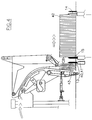
- the stacker designated as a whole by 1, has a support frame 2 in which a known and therefore not further described conveying path for a continuous stream 3 of scale layers 4 arranged in the manner of arrows runs in the direction of arrows F into the end section 5 of the guide section of the stitch layers comes in.
- a vibrating carpet 6 is assigned to this route section 5, the individual bands of which can be deflected between the wheels 7 and 8.
- Reference number 9 denotes a tensioning unit for tensioning the tapes of the carpet 6.
- the entire structure of the vibrating carpet can be pivoted about the axis of the deflection wheel 7.
- Means 10 for pretensioning the vibrating carpet are attached after the booklet package in order to generate the contact pressure of the carpet 6 on the booklet stream 3 required for pulling out or stripping off the individual booklet layers 4.
- the booklet positions 4 are guided against the package carrying and conveying track 12 consisting of known belt drives. These belts are mounted in support bars, not shown, which are part of the support frame 2 of the machine.
- the biasing means 10 consist, for example, of a piston-cylinder unit attached to the machine support frame 2.
- the stacker is also equipped with a separating blade 13, a support fork 14 and a stop fork 15 of the finished package, see FIG. 4, the separating blade 13 and the support and stop forks 14, 15 being retractable in a known and not shown manner.
- the separating blade 13 on the one hand and the forks 14 and 15 on the other hand are operatively connected to known adjusting means, not shown.
- the reference numerals 17 and 18 denote a circulation counter or a straight line of the upper edge of the booklet layers.
- the known stackers also have a device for temporarily stopping the booklet stream 3 for generating interruption points in the continuous booklet stream 3. Such means consist of, for example Press jaw, which can be provided at any point along the conveying path of the booklet stream.
- an adjusting device 20 is arranged, which in the example shown is a piston-cylinder unit, the control valve 21 of which is connected to the circulation counter designated 17 or the like.
- the separating blade 13 consists of two retractable tines 22, 23, each of which is assigned to piston-cylinder units 24, 25, which are attached to one in the direction of the arrow f1 below the Package conveyor track 12 movable back and forth, carrying the prepackage frame 27 are arranged.
- the frame 27 carrying the prepackage is slidably mounted on a central spar which carries the central belt of the web 12 and is driven, for example, in a manner not shown, by an annular belt which is deflected between two pulleys, one of which is one Drive motor is assigned.
- the support fork 14 and the stop fork 15 each consist of two prongs 30, 31 and 32, 33, which are assigned to a piston-cylinder unit for their retracting movement.
- the support fork 14 and the stop fork 15 are arranged on a frame 35 which, for example, is mounted similarly to the frame 27.
- the frames 27 and 35 are, for example, plate-shaped.
- the frame 35 is also driven in a manner not shown via an annular belt which is deflected between two pulleys, one of which is assigned to a drive motor.
- FIG. 5 also shows that stop and separating wedges 40, 41 are arranged on the prongs 22, 23 of the separating blade 13.
- the wedges 40, 41 are vertically displaceable on the prongs 22, 23 and are operatively connected to fixed guide cams, which are not shown in detail and with the stacker frame 2 are connected in one piece.
- the cams are designed in such a way that the stop wedges 40, 41 are moved vertically, namely between an upper position, FIGS. 1, 2 and 5, in which they protrude in height from the package conveyor track 12, but without reaching the lower free edge to reach the last booklet position 4a of a finished package 42, and a retracted position below the conveyor track 12, FIGS. 3 and 4.
- FIG. 1 shows the step in which the formation of a packet is completed.
- the separating blade 13 is in the retracted position in front of the infeed conveyor track 12 of the booklet flow 3.
- the stop wedges 40, 41 are in the raised waiting position.
- the frame 27 carrying the prepackage is withdrawn accordingly.
- the stop fork 15 is also withdrawn.
- the stitching layers 4 entering the package are introduced and positioned in a known manner by the vibrating carpet 6, which is prestressed by the piston-cylinder unit 10.
- the support fork 14 supports the package and moves in a known manner at a speed which corresponds to the speed of the package formation.
- the pulse controls the following steps to separate the package: via the control valve 21, the piston-cylinder unit 20 causes the oscillating carpet 6 to pivot out into the open position, see FIG. 2.
- the frame 27 moves with a rapid movement Run towards the package 42 and the protruding part of the stop wedges 40, 41 lies against the lower, free edge of the last stitch position 4a of the package 42.
- the carpet 6 is opened, a wide space can be formed to accommodate the incoming booklet layers.
- the tack layer 4b which comes immediately after the tack layer 4a, slides over the separating wedges and moves away from the tack layer 4a.
- the frame 35 leads the finished package 42 to the downstream treatment station, for example a station, not shown, where the package is pressed and tied after the end flaps have been attached.
- the frame 35 runs back quickly in a known manner, the prongs 32, 33 of the stop fork 15 retracting and then the prongs 30, 31 of the support fork 14 coming into contact with the first stitching position 4b of the prepackage, which is known to be the bottom of the package being formed.
- the tines 22, 23 of the separating blade 13 move back and when they move backwards, the stop wedges 40, 41, FIG. 1, slide into the package formation section.
- a sensor (not shown) or the like could give the packet separation pulse which determines the length of the packet.
Abstract
Description
Die Erfindung betrifft ein Verfahren zum Trennen von Heftlagenpaketen in Staplern und einen Stapler zum Durchführen des Verfahrens nach den Oberbegriffen der Patentansprüche 1 und 3.The invention relates to a method for separating staple stacks in stackers and a stacker for carrying out the method according to the preambles of
Bei den bekannten Verfahren zum Trennen von Heftlagenpaketen in senkrechten und waagerechten Staplern werden in der Regel zum Aufteilen der Pakete im kontinuierlichen Strom der ankommenden Heftlagen Unterbrechungsstellen geschaffen und dann wird in diese Unterbrechungsstellen eine Trennschaufel eingeschoben. Die bekannten Stapler weisen im wesentlichen eine Zuführungsstrecke der Heftlagen zum Paketbildungsbereich an einem Paktet-Bildungs- und Förderweg entlang, einen Schwingteppich zum Ausziehen der Heftlagen, eine Paketstützgabel und eine Paketanschlaggabel, die beide zurückziehbar und Versteilmitteln zugeordnet sind, eine zurückziehbare und ebenfalls Versteilmitteln zugeordnete Trennschaufel, wobei die Gabeln und die Schaufel mit Antriebsmitteln zur Herstellung eines Vorpakets bzw. eines fertigen Pakets in Wirkverbindung stehen, sowie einen Auflagenzähler oder dgl. auf.In the known methods for separating staple packs in vertical and horizontal stackers, breakpoints are generally created for dividing the packets in the continuous flow of the incoming booklet layers and then a separating blade is inserted into these breakpoints. The known stackers essentially have a feed path of the booklet layers to the package formation area along a package formation and conveying path, an oscillating carpet for pulling out the booklet layers, a package support fork and a package stop fork, both of which are retractable and associated with adjusting means, a retractable and also associated with adjusting means separating blade , wherein the forks and the bucket with drive means for producing a Prepackage or a finished package are in operative connection, as well as a circulation counter or the like.
Die zum Einführen der Trennschaufel erforderliche Unterbrechung des Heftlagenstromes ist insofern nachteilig, dass sich im Bereich, wo der Heftlagenstrom unterbrochen wird, mehrere Heftlagen so aufhäufen, dass sie ihre schuppenförmige Anordnung grösstenteils verlieren. Es ergibt sich dabei, dass diese Heftlagen an der der Auflageseite gegenüberliegenden Seite des anschliessenden Pakets entsprechend herausragen. Diese aus den Paketen herausragenden Heftlagen führen bekanntlich zu verschiedenen Störungen, die sowohl den Betrieb des Staplers als auch die anschliessenden Verpackungsvorgänge beeinträchtigen können. Solche Störungen machen wiederholte Eingriffe der Bedienungsperson erforderlich, verursachen Heftlagenausschuss und setzen die Produktivität herab.The interruption of the booklet flow required for inserting the separating blade is disadvantageous in that several booklet layers pile up in the area where the booklet stream is interrupted in such a way that they largely lose their scaly arrangement. The result of this is that these booklet layers protrude accordingly on the side of the subsequent package opposite the support side. As is well known, these stapling layers that stand out from the packages lead to various malfunctions that can affect both the operation of the truck and the subsequent packaging processes. Such disturbances require repeated operator intervention, cause staple waste and decrease productivity.
Manchmal können solche Vorsprünge sogar zur Stillsetzung des Staplers und folglich zum Stillstand der Rotationsdruckmaschine führen. Die erwähnten Störungen werden mit der gewünschten Erhöhung der Druckgeschwindigkeit häufiger, die es den moderneren Rotationsdruckmaschinen erlaubt, nunmehr eine Stundenleistung von 100.000 Auflagen zu erreichen.Sometimes such protrusions can even cause the stacker to shut down and consequently the rotary press to stop. The disturbances mentioned become more frequent with the desired increase in the printing speed, which allows the more modern rotary printing presses to now achieve an hourly output of 100,000 runs.
Der Erfindung liegt die Aufgabe zugrunde, die oben erwähnten Nachteile der bekannten Verfahren und Stapler zu beseitigen und ein Verfahren sowie einen Stapler anzugeben, mit denen sich ein einwandfreies Trennen der Heftlagenpakete bewerkstelligen lässt, und zwar ohne den Strom der ankommenden Heftlagen zu unterbrechen oder ihre Geschwindigkeit zu ändern.The object of the invention is to overcome the above-mentioned disadvantages of the known methods and stackers Eliminate and specify a method and a stacker, with which a perfect separation of the booklet packs can be achieved, without interrupting the flow of the incoming booklet layers or changing their speed.
Bei einem derartigen Verfahren wird diese Aufgabe mit den im kennzeichnenden Teil von Patentanspruch 1 angegebenen Merkmalen gelöst.In such a method, this object is achieved with the features specified in the characterizing part of patent claim 1.
Die in Patentanspruch 2 angegebenen Merkmale zielen auf ein sauberes Trennen des fertigen Pakets ohne Beschädigungen oder Verschiebungen der Heftlagen ab.The features specified in
Bei einem Stapler zum Durchführen des Verfahrens wird diese Aufgabe erfindungsgemäss mit den in Patentanspruch 3 angegebenen Merkmalen gelöst.In a stacker for carrying out the method, this object is achieved according to the invention with the features specified in
Der mit dem erfindungsgemässen Verfahren und der entsprechenden Vorrichtung erzielte wesentliche Vorteil besteht darin, dass die auf die Geschwindigkeitsänderung bzw. auf die Unterbrechung des Heftlagenstromes zurückzuführenden Störungen beseitigt werden. Es werden dadurch die erforderlichen Eingriffe der Bedienungspersonen verringert, was sehr wichtig ist, auch weil man bestrebt ist, einer Bedienungsperson nicht nur einen Stapler, sondern zwei Stapler zuzuteilen. Gleichzeitig wird ein Heftlagenausschuss und eine eventuelle Stillsetzung der Rotationsdruckmaschine oder der nachgeschalteten Verpackungsmaschinen ausgeschlossen und daher wird die jeweilige Maschinenleistung erhöht. Ein weiterer Vorteil ist in der Tatsache zu sehen, dass die vorgeschlagene Lösung eine beschränkte Anzahl zusätzlicher Bestandteile erfordert und mit wenigen Änderungen auch in bereits bestehende Stapler integriert werden kann.The main advantage achieved with the method according to the invention and the corresponding device is that the disturbances attributable to the change in speed or to the interruption of the booklet flow are eliminated. This reduces the required operator intervention, which is very important, also because efforts are made to assign not only one stacker but two stacker to one operator. At the same time, a stitching committee and a possible shutdown of the rotary printing press or the downstream one Packaging machines excluded and therefore the respective machine performance is increased. Another advantage can be seen in the fact that the proposed solution requires a limited number of additional components and can be integrated into existing forklifts with just a few changes.
Es ist ausserdem vorteilhaft, dass die betreffenden Stapler auch bei den hohen heutzutage erzielbaren Geschwindigkeiten der Rotationsdruckmaschinen zuverlässig arbeiten.It is also advantageous that the stackers in question operate reliably even at the high speeds of the rotary printing presses that can be achieved today.
Weitere vorteilhafte Ausgestaltungen des erfindungsgemässen Staplers sind in den Unteransprüchen angegeben.Further advantageous refinements of the stacker according to the invention are specified in the subclaims.
Die in Patentanspruch 4 angegebenen Merkmale betreffen eine einfache Ausführungsform der Erfindung, die sich leicht in den Rahmen des Staplers integrieren lässt.The features specified in
Aus Patentanspruch 5 ergibt sich eine vorteilhafte Ausführungsform der Führungsnocken, die eine einfache und raumsparenden Montage gestattet.An advantageous embodiment of the guide cams results from
Die Erfindung wird nachstehend an Hand eines in den Zeichnungen schematisch dargestellten Ausführungsbeispiels näher beschrieben. Es zeigen:
- Figur 1 einen waagerechten Stapler während der Fertigstellung eines Pakets, in einer seitlichen Teilansicht;
Figur 2 den Stapler während des Vorganges, bei dem die Länge eines fertigen Pakets festgelegt wird, in einer mit derjenigen von Figur 1 vergleichbaren Ansicht ;Figur 3 den Staplers im Augenblick der Trennung des fertigen Pakets, in einer Ansicht, die mit derjenigen von Figur 1 vergleichbaren ist;Figur 4 den Stapler während des Vorganges, bei dem der Transport zum Entfernen des fertigen Pakets eingeleitet und das nächste Vorpaket gebildet wird, in einer mit derjenigen von Figur 1 vergleichbaren Ansicht; undFigur 5 eine schematische perspektivische Ansicht der Trennschaufel und der Gabeln zur Bildung und zum Transport der Pakete gemäss der Erfindung.
- Figure 1 shows a horizontal stacker during the completion of a package, in a partial side view;
- Figure 2 shows the stacker in one with the process in which the length of a finished package is determined view comparable to that of FIG. 1;
- Figure 3 shows the stacker at the moment of separation of the finished package, in a view comparable to that of Figure 1;
- FIG. 4 shows the stacker during the process in which the transport for removing the finished package is initiated and the next prepackage is formed, in a view comparable to that of FIG. 1; and
- Figure 5 is a schematic perspective view of the separating blade and the forks for forming and transporting the packages according to the invention.
Einander gleiche Teile sind mit den gleichen Bezugszeichen bezeichnet.Parts that are identical to one another are identified by the same reference symbols.
Der insgesamt mit 1 bezeichnete Stapler weist einen Tragrahmen 2 auf, in dem ein an sich bekannter und daher nicht weiter geschilderter Förderweg für einen kontinuierlichen Strom 3 von schuppenartig angeordneten Heftlagen 4 verläuft, der in Richtung der Pfeile F in den Endabschnitt 5 der Führungsstrecke der Heftlagen einläuft.The stacker, designated as a whole by 1, has a
Diesem Streckenabschnitt 5 ist ein Schwingteppich 6 zugeordnet, dessen einzelne Bänder zwischen den Rädern 7 und 8 umgelenkt werden können. Mit dem Bezugszeichen 9 ist eine Spanneinheit zum Spannen der Bänder des Teppichs 6 bezeichnet. Der ganze Aufbau des Schwingteppichs ist um die Achse des Umlenkrades 7 schwenkbar. Am Teppich 6 sind Mittel 10 zum Vorspannen des Schwingteppichs nach dem Heftlagenpaket hin befestigt, um den zum Ausziehen bzw. Abstreifen der einzelnen Heftlagen 4 erforderlichen Anpressdruck des Teppichs 6 auf den Heftlagenstrom 3 zu erzeugen. Die Heftlagen 4 werden gegen die aus bekannten Riementrieben bestehenden Pakettrag- und Förderbahn 12 geführt. Diese Riemen sind in nicht dargestellten Stützholmen gelagert, die Teil des Tragrahmens 2 der Maschine sind.A vibrating
Die Vorspannmittel 10 bestehen zum Beispiel aus einer am Maschinentragrahmen 2 befestigten Kolben-Zylinder-Einheit.The biasing means 10 consist, for example, of a piston-cylinder unit attached to the
Der Stapler ist ausserdem mit einer Trennschaufel 13, einer Stützgabel 14 und einer Anschlaggabel 15 des fertigen Pakets ausgerüstet, siehe Figur 4, wobei die Trennschaufel 13 und die Stütz- und Anschlaggabeln 14, 15 auf bekannte und nicht weiter dargestellte Weise zurückziehbar sind. Die Trennschaufel 13 einerseits und die Gabeln 14 und 15 anderseits stehen mit bekannten, nicht weiter dargestellten Verstellmitteln in Wirkverbindung. Mit den Bezugszeichen 17 und 18 sind ein Auflagenzähler bzw. ein Geradeleger des oberen Randes der Heftlagen bezeichnet. Die bekannten Stapler weisen ausserdem eine Vorrichtung zum zeitweiligen Anhalten des Heftlagenstromes 3 zur Erzeugung von Unterbrechungsstellen im kontinuierlichen Heftlagenstrom 3 auf. Solche Mittel bestehen zum Beispiel aus einer Pressbacke, die an jeder beliebigen Stelle des Förderweges des Heftlagenstromes vorgesehen werden kann.The stacker is also equipped with a separating
Bisher wurde ein bekannter Stapler, zum Beispiel ein waagerechter Stapler beschrieben. Bei dem in einem solchen Stapler durchgeführten Verfahren zum Trennen des Pakets ist die Einführung der Trennschaufel in eine Unterbrechungsstelle vorgesehen, die das Ende des in Bildung begriffenen Pakets und den Anfang der Bildung des Vorpaktes für das nachfolgende Paket bestimmt. Der Einfachheit halber wird auf eine ausführliche Beschreibung des ganzen sich in den bekannten Staplern abwickelnden Verfahrens zur Bildung und zum Trennen der Pakete verzichtet.So far, a known stacker, for example a horizontal stacker, has been described. In the method for separating the package carried out in such a stacker, the introduction of the separation blade into an interruption point is provided, which determines the end of the package being formed and the beginning of the formation of the pre-package for the subsequent package. For the sake of simplicity, a detailed description of the entire process for forming and separating the packets which takes place in the known stackers is dispensed with.
Zur Durchführung des erfindungsgemässen Verfahrens, bei dein der Heftlagenstrom 3 ohne Unterbrechungen oder Geschwindigkeitsänderungen zugeführt wird, sind die nachstehend beschriebenen Verbesserungen der Stapler vorgesehen.In order to carry out the method according to the invention, in which the
Zwischen der Vorspann-Kolben-Zylinder-Einheit 10 und dem Staplerrahmen 2 ist eine Verstellvorrichtung 20 angeordnet, die im dargestellen Beispiel eine Kolben-Zylinder-Einheit ist, deren Steuerventil 21 mit dem mit 17 bezeichneten Auflagenzähler oder dgl. verbunden ist.Between the biasing piston-
Wie insbesondere aus Figur 5 ersichtlich, besteht die Trennschaufel 13 aus zwei zurückziehbaren Zinken 22, 23, die jeweils Kolben-Zylinder-Einheiten 24, 25 zugeordnet sind, die an einem in Pfeilrichtung f1 unterhalb der Paketförderbahn 12 hin- und herbewegbaren, das Vorpaket tragenden Gestell 27, angeordnet sind. Praktisch ist das, das Vorpaket tragende Gestell 27, an einem mittleren Holm verschiebbar gelagert, der den mittleren Riemen der Bahn 12 trägt und zum Beispiel in nicht dargestellter Weise durch einen ringförmigen Riemen angetrieben ist, der zwischen zwei Riemenscheiben umgelenkt ist, von denen eine einem Antriebsmotor zugeordnet ist.As can be seen in particular from FIG. 5, the
Im dargestellten Beispiel bestehen auch die Stützgabel 14 und die Anschlaggabel 15 jeweils aus zwei Zinken 30, 31 und 32, 33, die für ihre Einfahrbewegung einer Kolben-Zylinder-Einheit zugeordnet sind.In the example shown, the
Wie aus Figur 5 ersichtlich, sind die Stützgabel 14 und die Anschlaggabel 15 an einem Gestell 35 angeordnet, das zum Beispiel ähnlich wie das Gestell 27 gelagert ist. Die Gestelle 27 und 35 sind zum Beispiel plattenförmig ausgeführt. Das Gestell 35 ist ebenfalls in nicht dargestellter Weise über einen ringförmigen Riemen angetrieben, der zwischen zwei Riemenscheiben umgelenkt ist, von denen eine einem Antriebsmotor zugeordnet ist.As can be seen from FIG. 5, the
Figur 5 zeigt ausserdem, dass an den Zinken 22, 23 der Trennschaufel 13 Anschlag- und Trennkeile 40, 41 angeordnet sind. Die Keile 40, 41 sind senkrecht an den Zinken 22, 23 verschiebbar und stehen mit festen Führungsnocken in Wirkverbindung, die nicht im Einzelnen dargestellt und mit dem Staplerrahmen 2 einteilig verbunden sind. Die Nocken sind so ausgebildet, dass die Anschlagkeile 40, 41 senkrecht bewegt werden, und zwar zwischen eine obere Stellung, Figur 1, 2 und 5, in der sie aus der Paketförderbahn 12 in die Höhe herausragen, ohne jedoch bis zum unteren, freien Rand der letzten Heftlage 4a eines fertigen Pakets 42 zu reichen, und eine eingezogene Stellung unterhalb der Förderbahn 12, Figur 3 und 4.FIG. 5 also shows that stop and separating
Das erfindungsgemässe Pakettrennverfahren wird nun unter Bezug auf die Arbeitsweise des Staplers beschrieben.The packet separation method according to the invention will now be described with reference to the operation of the truck.
In Figur 1 ist der Schritt dargestellt, bei dem die Bildung eines Pakets vollendet wird. Die Trennschaufel 13 befindet sich in der zurückgezogenen Lage vor der Einlaufförderbahn 12 des Heftlagenstromes 3. Die Anschlagkeile 40, 41 befinden sich in angehobener Wartestellung. Das das Vorpaket tragende Gestell 27 ist entsprechend zurückgezogen. Die Anschlaggabel 15 ist ebenfalls zurückgezogen. Die in das Paket einlaufenden Heftlagen 4 werden durch den über die Kolben-Zylinder-Einheit 10 vorgespannten Schwingteppich 6 auf bekannte Art und Weise eingeführt und positioniert. Die Stützgabel 14 stützt das Paket und bewegt sich in bekannter Weise mit einer Geschwindigkeit, die der Geschwindigkeit der Paketbildung entspricht.FIG. 1 shows the step in which the formation of a packet is completed. The separating
Nach der durch einen zum Beispiel vom Auflagenzähler 17 gegebenen Impuls ermittelten Fertigstellung des Pakets, steuert der Impuls folgende Schritte zum Trennen des Pakets an: über das Steuerventil 21 veranlasst die Kolben-Zylinder-Einheit 20 das Ausschwenken des Schwingteppichs 6 in Öffnungsstellung, siehe Figur 2. Das Gestell 27 bewegt sich mit einem raschen Lauf zum Paket 42 hin und der hochragende Teil der Anschlagkeile 40, 41 legt sich am unteren, freien Rand der letzten Heftlage 4a des Pakets 42 an. Beim Öffnen des Teppichs 6 kann sich ein weiter Raum zur Aufnahme der einlaufenden Heftlagen bilden. Bei ihrer Abwärtsbewegung gleitet daher die Heftlage 4b, die unmittelbar nach der Heftlage 4a kommt, über die Trennkeile hinweg und entfernt sich von der Heftlage 4a. In diesem Augenblick befindet sich die zurückgezogene, in einer Ebene mit der ebenfalls zurückgezogenen Trennschaufel 13 liegende Anschlaggabel 15 in der unteren senkrechten Trennebene zwischen den Heftlagen 4a und 4b. Unmittelbar nach dem Ausschwenken des Schwingteppichs 6 in Öffnungsstellung (Pfeil F1, Figur 2) und dem Trennen der Heftlagen 4a und 4b, treten die Trennschaufel 13 und die Anschlaggabel 15 aus, Figur 3. Dadurch findet das saubere Trennen des fertigen Pakets 42 und des nachfolgenden im Vorformen begriffenen Pakets 43 statt, Figur 3.According to the one from the
Nachdem die Bildung des Vorpakets 43 angefangen hat, wird die Kolben-Zylinder-Einheit 20 in Pfeilrichtung F2, Figur 3, zurückgeführt und der Schwingteppich 6 wird in Schließstellung geschwenkt. Inzwischen haben sich die mit den entsprechenden Führungsnocken in Wirkverbindung stehenden Anschlagkeile 40, 41 nach unten bewegt, Figur 4.After the formation of the pre-package 43 has started, the piston-
Während sich das das Vorpaket tragende Gestell 27 zur Bildung des Vorpakets weiter bewegt, führt das Gestell 35 das fertige Paket 42 zur nachgeschalteten Behandlungsstation, zum Beispiel einer nicht dargestellten Station, wo nach Anbringen der Endklappen das Paket gepresst und festgebunden wird. Nach Überführung des Pakets 42 zur nachgeschalteten Behandlungsstation, läuft das Gestell 35 in bekannter Weise rasch zurück, wobei die Zinken 32, 33 der Anschlaggabel 15 zurückfahren und anschliessend die Zinken 30, 31 der Stützgabel 14 gegen die erste Heftlage 4b des Vorpakets zur Anlage kommen, das bekanntlich den Boden des in Bildung begriffenen Pakets darstellt. Nun fahren die Zinken 22, 23 der Trennschaufel 13 zurück und bei ihrer Rückwärtsbewegung schieben sich die Anschlagkeile 40, 41, Figur 1, in die Paketbildungsstrecke ein.While the
Aus der obigen Beschreibung geht die Tatsache hervor, dass sich mit dem erfindungsgemässen Verfahren und mit einem Stapler zur Duchführung desselben ein sauberes und genaues Trennen der Heftlagenpakete bewerkstelligen lässt, und zwar ohne den Strom 3 der einlaufenden Heftlagen zu unterbrechen oder ihre Geschwindigkeit zu ändern. Durch die Anordnung der Anschlag- und Trennkeile 40, 41 an der Trennschaufel 13 kann man den wesentlichen Teil des bekannten Paketbildungsablaufes sowie den bekannten Aufbau der Stapler bestehen lassen.From the above description it is evident that the method according to the invention and a stacker for carrying out the same can be used to achieve a clean and precise separation of the stapling stacks, without interrupting the
Anstelle eines Auflagenzählers 17 könnte ein nicht dargestellter Sensor oder dgl. den die Länge des Pakets ermittelnden Pakettrennimpuls geben.Instead of a
Obwohl die Erfindung in Zusammenhang mit einem waagerechten Stapler geschildert wurde, kann ihre Lehre ohne weiteres auch für senkrechte Stapler zur Anwendung kommen.Although the invention has been described in connection with a horizontal stacker, its teaching can also be used for vertical stackers without further ado.
Claims (5)
Applications Claiming Priority (2)
| Application Number | Priority Date | Filing Date | Title |
|---|---|---|---|
| ITMI950907 | 1995-05-05 | ||
| ITMI950907A IT1274434B (en) | 1995-05-05 | 1995-05-05 | PROCEDURE FOR SEPARATING PACKAGES OF SIGNATURES IN STACKERS AND STACKER FOR THE EXECUTION OF THE PROCEDURE |
Publications (3)
| Publication Number | Publication Date |
|---|---|
| EP0741101A2 true EP0741101A2 (en) | 1996-11-06 |
| EP0741101A3 EP0741101A3 (en) | 1997-07-30 |
| EP0741101B1 EP0741101B1 (en) | 2002-01-09 |
Family
ID=11371538
Family Applications (1)
| Application Number | Title | Priority Date | Filing Date |
|---|---|---|---|
| EP96107015A Expired - Lifetime EP0741101B1 (en) | 1995-05-05 | 1996-05-03 | Method for separating a stack of signatures in a stacker and stacker for performing this method |
Country Status (5)
| Country | Link |
|---|---|
| EP (1) | EP0741101B1 (en) |
| DE (1) | DE59608547D1 (en) |
| DK (1) | DK0741101T3 (en) |
| ES (1) | ES2169171T3 (en) |
| IT (1) | IT1274434B (en) |
Cited By (5)
| Publication number | Priority date | Publication date | Assignee | Title |
|---|---|---|---|---|
| FR2777876A1 (en) * | 1998-04-24 | 1999-10-29 | Realisations Etudes Et Commerc | Automatic stacker for books |
| WO2000040494A1 (en) * | 1999-01-08 | 2000-07-13 | Realisations, Etudes & Commercialisation De Materiel Pour L'industrie, Recmi | Device for stacking sections in cartridge form |
| EP1405809A1 (en) * | 2002-10-02 | 2004-04-07 | Müller Martini Holding AG | Device for forming parcels of stacked products |
| FR2856391A1 (en) * | 2003-06-20 | 2004-12-24 | Recmi Ind | Automatic horizontal stacking device for book cartons, has four stacking fingers and stop fingers, where each stacking or stop finger is driven in projection above and below stacking table independent of other fingers |
| EP2316767A1 (en) * | 2009-11-03 | 2011-05-04 | Müller Martini Holding AG | Device and method for manufacturing printed product stacks |
Families Citing this family (1)
| Publication number | Priority date | Publication date | Assignee | Title |
|---|---|---|---|---|
| DE102021109361A1 (en) | 2021-04-14 | 2022-10-20 | Sig Technology Ag | Device and method for grouping packing sleeves |
Citations (4)
| Publication number | Priority date | Publication date | Assignee | Title |
|---|---|---|---|---|
| GB1163666A (en) * | 1967-03-15 | 1969-09-10 | Kartonagenmaschinenwerk Kama V | Device for Grouping Folding Cartons or the like. |
| GB1303135A (en) * | 1970-02-25 | 1973-01-17 | ||
| US4172531A (en) * | 1975-12-29 | 1979-10-30 | Grapha-Holding Ag | Apparatus for transforming a stream of overlapping paper sheets into a staple of sheets |
| US4772003A (en) * | 1987-02-24 | 1988-09-20 | Dainihon Insatsu Kabushiki Kaisha | Apparatus for stacking signatures or the like |
-
1995
- 1995-05-05 IT ITMI950907A patent/IT1274434B/en active IP Right Grant
-
1996
- 1996-05-03 DE DE59608547T patent/DE59608547D1/en not_active Expired - Fee Related
- 1996-05-03 EP EP96107015A patent/EP0741101B1/en not_active Expired - Lifetime
- 1996-05-03 DK DK96107015T patent/DK0741101T3/en active
- 1996-05-03 ES ES96107015T patent/ES2169171T3/en not_active Expired - Lifetime
Patent Citations (4)
| Publication number | Priority date | Publication date | Assignee | Title |
|---|---|---|---|---|
| GB1163666A (en) * | 1967-03-15 | 1969-09-10 | Kartonagenmaschinenwerk Kama V | Device for Grouping Folding Cartons or the like. |
| GB1303135A (en) * | 1970-02-25 | 1973-01-17 | ||
| US4172531A (en) * | 1975-12-29 | 1979-10-30 | Grapha-Holding Ag | Apparatus for transforming a stream of overlapping paper sheets into a staple of sheets |
| US4772003A (en) * | 1987-02-24 | 1988-09-20 | Dainihon Insatsu Kabushiki Kaisha | Apparatus for stacking signatures or the like |
Cited By (10)
| Publication number | Priority date | Publication date | Assignee | Title |
|---|---|---|---|---|
| FR2777876A1 (en) * | 1998-04-24 | 1999-10-29 | Realisations Etudes Et Commerc | Automatic stacker for books |
| WO1999055611A1 (en) * | 1998-04-24 | 1999-11-04 | Realisations, Etudes & Commercialisation De Materiel Pour L'industrie, Recmi | Stacking device and printed sections in the form of cartridges |
| US6782678B1 (en) * | 1998-04-24 | 2004-08-31 | Realisations, Etudes & Co Commercialisation De Materiel Pour L'industrie, Recmi | Stacking device and printed sections in the form of cartridges |
| WO2000040494A1 (en) * | 1999-01-08 | 2000-07-13 | Realisations, Etudes & Commercialisation De Materiel Pour L'industrie, Recmi | Device for stacking sections in cartridge form |
| FR2788261A1 (en) * | 1999-01-08 | 2000-07-13 | Realisations Etudes Et Commerc | DIPOSITIVE FOR STACKING NOTEBOOKS IN THE FORM OF CARTRIDGES |
| EP1405809A1 (en) * | 2002-10-02 | 2004-04-07 | Müller Martini Holding AG | Device for forming parcels of stacked products |
| US7021035B2 (en) | 2002-10-02 | 2006-04-04 | Müller Martini Holding AG | Apparatus for producing stack bundles |
| FR2856391A1 (en) * | 2003-06-20 | 2004-12-24 | Recmi Ind | Automatic horizontal stacking device for book cartons, has four stacking fingers and stop fingers, where each stacking or stop finger is driven in projection above and below stacking table independent of other fingers |
| EP2316767A1 (en) * | 2009-11-03 | 2011-05-04 | Müller Martini Holding AG | Device and method for manufacturing printed product stacks |
| US8413792B2 (en) | 2009-11-03 | 2013-04-09 | Mueller Martini Holding Ag | Method and device for producing stacks composed of printed products |
Also Published As
| Publication number | Publication date |
|---|---|
| ITMI950907A0 (en) | 1995-05-05 |
| EP0741101B1 (en) | 2002-01-09 |
| ES2169171T3 (en) | 2002-07-01 |
| ITMI950907A1 (en) | 1996-11-05 |
| DE59608547D1 (en) | 2002-02-14 |
| EP0741101A3 (en) | 1997-07-30 |
| DK0741101T3 (en) | 2002-04-29 |
| IT1274434B (en) | 1997-07-17 |
Similar Documents
| Publication | Publication Date | Title |
|---|---|---|
| EP0187344B1 (en) | Method and device for the production of single stacks consisting of a fan folded web | |
| EP0242763A2 (en) | Apparatus for cutting piles of sheets | |
| EP0189090A2 (en) | Folding device of webs | |
| DE2728280A1 (en) | DEVICE FOR STACKING PLATES | |
| DE2125991A1 (en) | Method and apparatus for transporting stacked flat objects in succession to a collection | |
| EP0243799B1 (en) | Device for folding webs | |
| CH647735A5 (en) | METHOD FOR PRODUCING STACKS FROM FOLDED PRINTED SHEETS AND DEVICE FOR CARRYING OUT THE METHOD. | |
| CH680363A5 (en) | ||
| EP0418529B1 (en) | Apparatus for trilateral trimming of signatures | |
| EP0362740B1 (en) | Method and device for producing and conveying stacks of foil-lengths | |
| EP0856396B1 (en) | Flexible device for forming carton blanks | |
| DE1235217B (en) | Packing machine, in particular cigarette packing machine | |
| EP1405809B1 (en) | Device for forming parcels of stacked products | |
| EP0606113A2 (en) | Device for placing reinforcing elements on indexing inserts | |
| EP0392139A2 (en) | Device for laying down sheafs of sheets, particularly paper sheets, onto a pile | |
| EP2498983B1 (en) | Apparatus and method for forming stacks of bags | |
| DE4401818C2 (en) | Clamping device, in particular for clamping a sheet package when changing stacks in stacking devices for sheets of paper or cardboard | |
| EP0243944A1 (en) | Device for the production of bundled piles of folded paper sheets | |
| EP1334938A1 (en) | Device for producing bound printed products | |
| DE3432385A1 (en) | DEVICE FOR PUNCHING STACKS FROM FLAT WORKPIECES | |
| EP0741101B1 (en) | Method for separating a stack of signatures in a stacker and stacker for performing this method | |
| CH371732A (en) | Device for feeding and opening folded cardboard sleeves, in particular for packaging machines | |
| EP0529204A1 (en) | Apparatus for conveying plates towards a deep drawing machine | |
| EP1515894B1 (en) | System for packaging a flexible web that is layered in zigzag loops, in particular a textile web | |
| DE1085409B (en) | Device for dispensing, counting and stacking bags into packages and for bundling the stacks of packages |
Legal Events
| Date | Code | Title | Description |
|---|---|---|---|
| PUAI | Public reference made under article 153(3) epc to a published international application that has entered the european phase |
Free format text: ORIGINAL CODE: 0009012 |
|
| AK | Designated contracting states |
Kind code of ref document: A2 Designated state(s): BE CH DE DK ES FR GB IT LI NL |
|
| PUAL | Search report despatched |
Free format text: ORIGINAL CODE: 0009013 |
|
| 17P | Request for examination filed |
Effective date: 19970430 |
|
| AK | Designated contracting states |
Kind code of ref document: A3 Designated state(s): BE CH DE DK ES FR GB IT LI NL |
|
| 17Q | First examination report despatched |
Effective date: 19991110 |
|
| GRAG | Despatch of communication of intention to grant |
Free format text: ORIGINAL CODE: EPIDOS AGRA |
|
| GRAG | Despatch of communication of intention to grant |
Free format text: ORIGINAL CODE: EPIDOS AGRA |
|
| GRAH | Despatch of communication of intention to grant a patent |
Free format text: ORIGINAL CODE: EPIDOS IGRA |
|
| RAP1 | Party data changed (applicant data changed or rights of an application transferred) |
Owner name: CIVIEMME S.P.A. |
|
| GRAH | Despatch of communication of intention to grant a patent |
Free format text: ORIGINAL CODE: EPIDOS IGRA |
|
| GRAA | (expected) grant |
Free format text: ORIGINAL CODE: 0009210 |
|
| REG | Reference to a national code |
Ref country code: GB Ref legal event code: IF02 |
|
| AK | Designated contracting states |
Kind code of ref document: B1 Designated state(s): BE CH DE DK ES FR GB IT LI NL |
|
| REG | Reference to a national code |
Ref country code: CH Ref legal event code: EP |
|
| REF | Corresponds to: |
Ref document number: 59608547 Country of ref document: DE Date of ref document: 20020214 |
|
| REG | Reference to a national code |
Ref country code: CH Ref legal event code: NV Representative=s name: FREI PATENTANWALTSBUERO |
|
| REG | Reference to a national code |
Ref country code: DK Ref legal event code: T3 |
|
| GBT | Gb: translation of ep patent filed (gb section 77(6)(a)/1977) |
Effective date: 20020404 |
|
| PGFP | Annual fee paid to national office [announced via postgrant information from national office to epo] |
Ref country code: GB Payment date: 20020522 Year of fee payment: 7 |
|
| PGFP | Annual fee paid to national office [announced via postgrant information from national office to epo] |
Ref country code: FR Payment date: 20020523 Year of fee payment: 7 |
|
| PGFP | Annual fee paid to national office [announced via postgrant information from national office to epo] |
Ref country code: NL Payment date: 20020524 Year of fee payment: 7 Ref country code: ES Payment date: 20020524 Year of fee payment: 7 |
|
| PGFP | Annual fee paid to national office [announced via postgrant information from national office to epo] |
Ref country code: DK Payment date: 20020527 Year of fee payment: 7 Ref country code: BE Payment date: 20020527 Year of fee payment: 7 |
|
| PGFP | Annual fee paid to national office [announced via postgrant information from national office to epo] |
Ref country code: CH Payment date: 20020528 Year of fee payment: 7 |
|
| PGFP | Annual fee paid to national office [announced via postgrant information from national office to epo] |
Ref country code: DE Payment date: 20020604 Year of fee payment: 7 |
|
| REG | Reference to a national code |
Ref country code: ES Ref legal event code: FG2A Ref document number: 2169171 Country of ref document: ES Kind code of ref document: T3 |
|
| ET | Fr: translation filed | ||
| PLBE | No opposition filed within time limit |
Free format text: ORIGINAL CODE: 0009261 |
|
| STAA | Information on the status of an ep patent application or granted ep patent |
Free format text: STATUS: NO OPPOSITION FILED WITHIN TIME LIMIT |
|
| 26N | No opposition filed | ||
| PG25 | Lapsed in a contracting state [announced via postgrant information from national office to epo] |
Ref country code: GB Free format text: LAPSE BECAUSE OF NON-PAYMENT OF DUE FEES Effective date: 20030503 |
|
| PG25 | Lapsed in a contracting state [announced via postgrant information from national office to epo] |
Ref country code: ES Free format text: LAPSE BECAUSE OF NON-PAYMENT OF DUE FEES Effective date: 20030505 |
|
| PG25 | Lapsed in a contracting state [announced via postgrant information from national office to epo] |
Ref country code: LI Free format text: LAPSE BECAUSE OF NON-PAYMENT OF DUE FEES Effective date: 20030531 Ref country code: CH Free format text: LAPSE BECAUSE OF NON-PAYMENT OF DUE FEES Effective date: 20030531 Ref country code: BE Free format text: LAPSE BECAUSE OF NON-PAYMENT OF DUE FEES Effective date: 20030531 |
|
| BERE | Be: lapsed |
Owner name: *CIVIEMME S.P.A. Effective date: 20030531 |
|
| PG25 | Lapsed in a contracting state [announced via postgrant information from national office to epo] |
Ref country code: NL Free format text: LAPSE BECAUSE OF NON-PAYMENT OF DUE FEES Effective date: 20031201 Ref country code: DK Free format text: LAPSE BECAUSE OF NON-PAYMENT OF DUE FEES Effective date: 20031201 |
|
| PG25 | Lapsed in a contracting state [announced via postgrant information from national office to epo] |
Ref country code: DE Free format text: LAPSE BECAUSE OF NON-PAYMENT OF DUE FEES Effective date: 20031202 |
|
| GBPC | Gb: european patent ceased through non-payment of renewal fee |
Effective date: 20030503 |
|
| REG | Reference to a national code |
Ref country code: DK Ref legal event code: EBP |
|
| REG | Reference to a national code |
Ref country code: CH Ref legal event code: PL |
|
| PG25 | Lapsed in a contracting state [announced via postgrant information from national office to epo] |
Ref country code: FR Free format text: LAPSE BECAUSE OF NON-PAYMENT OF DUE FEES Effective date: 20040130 |
|
| NLV4 | Nl: lapsed or anulled due to non-payment of the annual fee |
Effective date: 20031201 |
|
| REG | Reference to a national code |
Ref country code: FR Ref legal event code: ST |
|
| REG | Reference to a national code |
Ref country code: ES Ref legal event code: FD2A Effective date: 20030505 |
|
| PG25 | Lapsed in a contracting state [announced via postgrant information from national office to epo] |
Ref country code: IT Free format text: LAPSE BECAUSE OF NON-PAYMENT OF DUE FEES Effective date: 20050503 |