EP0172584A2 - Kontrollsystem mit Berechtigungskarte und Vorrichtung zum Entwerten - Google Patents
Kontrollsystem mit Berechtigungskarte und Vorrichtung zum Entwerten Download PDFInfo
- Publication number
- EP0172584A2 EP0172584A2 EP85110736A EP85110736A EP0172584A2 EP 0172584 A2 EP0172584 A2 EP 0172584A2 EP 85110736 A EP85110736 A EP 85110736A EP 85110736 A EP85110736 A EP 85110736A EP 0172584 A2 EP0172584 A2 EP 0172584A2
- Authority
- EP
- European Patent Office
- Prior art keywords
- card
- heating elements
- value fields
- reading
- authorization
- Prior art date
- Legal status (The legal status is an assumption and is not a legal conclusion. Google has not performed a legal analysis and makes no representation as to the accuracy of the status listed.)
- Granted
Links
Images
Classifications
-
- G—PHYSICS
- G06—COMPUTING OR CALCULATING; COUNTING
- G06K—GRAPHICAL DATA READING; PRESENTATION OF DATA; RECORD CARRIERS; HANDLING RECORD CARRIERS
- G06K19/00—Record carriers for use with machines and with at least a part designed to carry digital markings
- G06K19/06—Record carriers for use with machines and with at least a part designed to carry digital markings characterised by the kind of the digital marking, e.g. shape, nature, code
- G06K19/08—Record carriers for use with machines and with at least a part designed to carry digital markings characterised by the kind of the digital marking, e.g. shape, nature, code using markings of different kinds or more than one marking of the same kind in the same record carrier, e.g. one marking being sensed by optical and the other by magnetic means
- G06K19/10—Record carriers for use with machines and with at least a part designed to carry digital markings characterised by the kind of the digital marking, e.g. shape, nature, code using markings of different kinds or more than one marking of the same kind in the same record carrier, e.g. one marking being sensed by optical and the other by magnetic means at least one kind of marking being used for authentication, e.g. of credit or identity cards
- G06K19/12—Record carriers for use with machines and with at least a part designed to carry digital markings characterised by the kind of the digital marking, e.g. shape, nature, code using markings of different kinds or more than one marking of the same kind in the same record carrier, e.g. one marking being sensed by optical and the other by magnetic means at least one kind of marking being used for authentication, e.g. of credit or identity cards the marking being sensed by magnetic means
-
- G—PHYSICS
- G06—COMPUTING OR CALCULATING; COUNTING
- G06K—GRAPHICAL DATA READING; PRESENTATION OF DATA; RECORD CARRIERS; HANDLING RECORD CARRIERS
- G06K1/00—Methods or arrangements for marking the record carrier in digital fashion
- G06K1/12—Methods or arrangements for marking the record carrier in digital fashion otherwise than by punching
- G06K1/126—Methods or arrangements for marking the record carrier in digital fashion otherwise than by punching by photographic or thermographic registration
-
- G—PHYSICS
- G06—COMPUTING OR CALCULATING; COUNTING
- G06K—GRAPHICAL DATA READING; PRESENTATION OF DATA; RECORD CARRIERS; HANDLING RECORD CARRIERS
- G06K7/00—Methods or arrangements for sensing record carriers, e.g. for reading patterns
- G06K7/08—Methods or arrangements for sensing record carriers, e.g. for reading patterns by means detecting the change of an electrostatic or magnetic field, e.g. by detecting change of capacitance between electrodes
- G06K7/082—Methods or arrangements for sensing record carriers, e.g. for reading patterns by means detecting the change of an electrostatic or magnetic field, e.g. by detecting change of capacitance between electrodes using inductive or magnetic sensors
- G06K7/087—Methods or arrangements for sensing record carriers, e.g. for reading patterns by means detecting the change of an electrostatic or magnetic field, e.g. by detecting change of capacitance between electrodes using inductive or magnetic sensors flux-sensitive, e.g. magnetic, detectors
-
- G—PHYSICS
- G06—COMPUTING OR CALCULATING; COUNTING
- G06Q—INFORMATION AND COMMUNICATION TECHNOLOGY [ICT] SPECIALLY ADAPTED FOR ADMINISTRATIVE, COMMERCIAL, FINANCIAL, MANAGERIAL OR SUPERVISORY PURPOSES; SYSTEMS OR METHODS SPECIALLY ADAPTED FOR ADMINISTRATIVE, COMMERCIAL, FINANCIAL, MANAGERIAL OR SUPERVISORY PURPOSES, NOT OTHERWISE PROVIDED FOR
- G06Q20/00—Payment architectures, schemes or protocols
- G06Q20/30—Payment architectures, schemes or protocols characterised by the use of specific devices or networks
- G06Q20/34—Payment architectures, schemes or protocols characterised by the use of specific devices or networks using cards, e.g. integrated circuit [IC] cards or magnetic cards
- G06Q20/343—Cards including a counter
- G06Q20/3433—Cards including a counter the counter having monetary units
-
- G—PHYSICS
- G07—CHECKING-DEVICES
- G07F—COIN-FREED OR LIKE APPARATUS
- G07F7/00—Mechanisms actuated by objects other than coins to free or to actuate vending, hiring, coin or paper currency dispensing or refunding apparatus
- G07F7/02—Mechanisms actuated by objects other than coins to free or to actuate vending, hiring, coin or paper currency dispensing or refunding apparatus by keys or other credit registering devices
Definitions
- the invention relates to a device for checking and validating authorization cards provided with value fields and a magnetizable data carrier, with a reading device formed by Hall generators, which reads the data corresponding to the value fields, which are magnetically recorded on the magnetizable data carrier of the card a writing device formed from magnets and with a device for optically visible validation of the authorization card.
- Such a device is known from German Offenlegungsschrift 30 01 888.
- Hall generators as a reading device, the known device for winter sports cards is in itself excellently suitable, since it is not only tamper-proof, but also insensitive to environmental influences, such as dirt, ice and snow, and deformations, such as kinks in the card.
- Such cards with value fields are also referred to as point cards.
- the desired number of points is magnetized onto the magnetizable data carrier of the card.
- the optical visible validation takes place in the device according to German Offenlegungsschrift 30 01 888 in such a way that when the card is guided past the reading device it controls a feed which transports the card to a punching device which removes the magnetized points to be devalued from the card punched out. If the card is to be fed by hand to the punching device by the user, then the feed can be replaced by a stop adjustable via the reading device.
- winter sports cards generally have carrier layers and / or protective layers made of plastic, i.e. they are relatively stiff.
- the punching device of the known device must be made relatively bulky. It is therefore not only subject to considerable wear, it is also relatively slow. In the embodiment of the known device, which has the adjustable stop, it can then happen that when the card is quickly inserted and removed from the control device by hand by the user, the punched-out points with the points to be devalued after the reading device are no longer to match.
- the other embodiment, in which the card is transported to the punching device with a feed, is generally not usable in winter sports resorts, because e.g. non-transferable cards, such as ski passes, are firmly attached to the skier's clothing and therefore cannot be transported through the device.
- the card validation device also having transport rollers according to German Offenlegungsschrift 21 43 183 is therefore also unusable for winter sports cards which are attached to the user.
- the device according to German Offenlegungsschrift 21 43 183 has the disadvantage that the optically visible cancellation takes place by means of a stamp print, which is hardly possible with a moist card, can be easily blurred, does not permit an outer protective film made of plastic for the card and one maintenance-intensive (e.g. by changing the ribbon) and fault-prone printing unit required.
- thermosensitive layer which has a thermographic or thermosensitive layer.
- the validator is provided with heating elements arranged transversely to the pass-through path of the card, which are opposed by an optical reading device on the other side of the pass-through path of the card data read by the reading device are forwarded to a computing system.
- a computing system In order to devalue the number of points required for using the relevant gondola lift or the relevant lift, a corresponding number of heating elements is heated with the aid of the computer system, as a result of which black points are formed at the relevant points in the thermosensitive layer. If the card is dirty, validation errors occur. Likewise, reading errors result from the thermosensitive layer becoming discolored over time.
- the invention has for its object to provide a device with the point cards, which are attached to the clothing of the card user and possibly dirty, iced or deformed, can be subjected to a quick check and which performs a quick magnetic and optical validation.
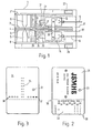
- a slot 4 is provided in a housing 1 between an upper and a lower guide plate 2 or 3, into which the authorization card, not shown in FIG. 1, is inserted.
- the electromagnets of the writing device 5 are opposite ten Hall generators on the top of the slot 4, which form the reading device 6, namely that a Hall generator is arranged exactly opposite each electromagnet. Two other Hall generators read the clock track, which is discussed in more detail below.
- the Hall generators of the reading device 6 and the electromagnets of the writing device 5 are connected to printed circuits 7 and 8.
- heating elements 9 and 10 are arranged in the insertion direction behind the writing device 5 and the reading device 6 above and below the slot.
- the heating elements 9 and 10 can consist of ceramic combs with individual heating resistors which are heated and cooled to 400 ° C. in the order of milliseconds and can be controlled individually.
- Ceramic combs of this type are commercially available as print heads for thermosensitive paper.
- the heating elements 9 and 10 are arranged transversely to the insertion direction of the authorization card.
- the upper and lower guide plates 2 and 3 each have a recess 11 or 12 in order to be able to bring the heating elements 9 and 10 into contact with the authorization card.
- the heating elements 9 and 10 are brought into contact with the authorization card by actuating an associated electromagnet 13 and 14 via electrical lines 15 and 16.
- the heating elements 9 and 10 are each fastened to a holder 17 and 18, which is arranged transversely to the direction of insertion extending to the guide plates 2 and 3 parallel axis are arranged on the guide plates 2 and 3, respectively.
- the pivot axes of the brackets 17 and 18 are arranged behind the heating elements 9 and 10 in the direction of insertion.
- the brackets 17 and 18 are pivoted away from the slot 4 by tension springs 19 and 20, which are fastened to the housing 1 at the top and bottom, respectively.
- each electromagnet 13 and 14 for pivoting the brackets 17 and 18, an armature 21 and 22 is arranged displaceably in the direction of insertion.
- each armature 21 and 22 is provided with a roller 23 and 24, which engages on the side of the holder 17 and 18 facing away from the slot 4.
- the armature 21 or 22 is then moved out of the magnet 13 or 14 in the direction of the end with the heating elements 17 or 18 which is pulled up or down by the spring 19 or 20 moves, whereby the roller 23 or 24 in question pivots the bracket 17 or 18 towards the slot 4, so that the heating elements 9 and 10 with the loading authorization card in slot 4 can come into contact.
- the electromagnets 13 and 14 are fastened by webs 25, for example on the upper and lower guide plates 2 and 3.
- the device also has a stop 26 for the authorization card when it is inserted into slot 4. Furthermore, a connection 27 or 28 is provided on the upper or lower printed circuit 7 or 8, each connection 27 or 28 leading to a computing system, not shown. The same controls the heating elements 9, 10 via the connections 9 'and 10'.
- FIG. 1 An embodiment of an authorization card having value fields, which is suitable for the device according to FIG. 1, is shown in FIG.
- the authorization card or point card is divided into two optically visible areas 29 and 30.
- Area 29 contains information that is the same for all point cards in the winter sports area in question, i.e. the name of the winter sports area, the name of the individual lifts and cable cars for which the card is valid, advertising information, etc.
- the area 30 has a thermosensitive layer.
- the visibly writable area 30 of the point card contains the information that is visibly recorded when the point card is purchased with a thermal printer, for example the total number of points, type of user (adult, child, free card and the like) and the price of the card .
- the area 30 of the authorization card contains a table 32.
- the ordinate and an abscissa indicate the total number of points on the point card, the maximum number of points available in table 32 being those If the points card is purchased, it can already be canceled if it exceeds the total number of points in column 31.
- the points devalued when the card was purchased are shown in FIG. 2 by crosses in table 32.
- the rest of Table 32 is blank when purchasing the points card.
- a hole 33 in the card serves to attach the card to the user by means of a tape or the like.
- a magnetizable layer 34 is provided as the magnetizable data carrier. According to FIG. 3, the magnetizable layer 34 extends over the full width of the card and is arranged inside the card. It has a clock track 35, which is used to position the card when reading and writing on the magnetizable layer 34 and to actuate the electromagnets 13 and 14, that is, for optically visible cancellation by means of the heating electrodes 9 and 10. Furthermore, line-shaped binary codes are magnetized onto the layer 34. The binary codes or bits of line 36 correspond to the valid points still present on the card.
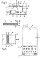
- FIG. 4 shows a cross section through an authorization card.
- 38 denotes a thin transparent plastic layer, 30 the thermosensitive layer, 39 a plastic backing, 34 the magnetizable layer and 40 a printable paper layer.
- An identification mark 37 in the magnetic layer 34 indicates a "high” or "low”, so that the computer system determines the position of the card, i.e. whether the area 30 with the thermosensitive layer is at the top or at the bottom, can be taken into account in such a way that it excites either the electromagnet 13 or the electromagnet 14 and controls the heating elements 9 or the heating elements 10 for optically visible validation of the correct side of the point card.
- the card is now pushed into slot 4 up to the stop 26.
- that of the heating elements 9 or 10 is then controlled and heated by the computing system or the writing voltage is applied to it, which leads to blackening at point “3” according to table 32 of the thermosensitive region 30 of the card , as shown in Figure 2.
- the magnetic clock track 35 enables precise positioning of the heating element with respect to the card. This redaction must occur within milliseconds so that the accuracy of the cancellation is not affected by the speed at which the card is pulled out.
- FIGS. 5 and 6 show a further embodiment of a device for optically visible validation of a point card, in which the last-mentioned requirement is certainly fulfilled.
- the device according to FIGS. 5 and 6 replaces the part framed in dashed lines in FIG. 2.
- the same parts are designated with the same reference numbers.
- the optical evaluation device has, at approximately the height of the guide slot 4, a plate-shaped holder 42 which can be pivoted about an axis 41 extending transversely to the card insertion direction and which has strip-shaped heating elements 43 and 44 at the end facing away from the pivot axis 41 above and below is provided, wherein each heating element 43 can be connected around the edge of the holder 42 to the relevant heating element 44 on the other side of the holder 42. Via lateral guide webs 45, the card can be pushed through the guide slot 4 up to the stop 26 over the entire length of the heating elements 43 or 44.
- the heating elements 43 and 44 are controlled by the computer system via connections 46.
- the holder 42 is connected via a lever 47 against the force of the tension spring 48 to the armature 49 of an electromagnet 50, which is controlled by the computer system via connections 51.
- Another tension spring 52 is arranged between the armature 49 and the lever arm 47. The spring 52 has a greater spring force than the spring 48.
- the electromagnet 50 in the non-excited state. If the identification mark 37 of the reading device 6 indicates that the thermosensitive layer is at the bottom, the electromagnet 50 remains in this state when the card is inserted until it is indicated via the clock track 35 that the card is at the stop 26. By excitation of the electromagnet 50, the holder 42 then pivots upward, so that the heating elements 43 come into contact with the area 30 of the card with the thermosensitive layer and that heating element 43 which has been activated by the computer system in the area 30 a line records.
- the electromagnet 50 is energized immediately when the identification mark 37 passes the reading device 6, so that the holder 42 Figure 5 in dashed upward position.
- the electromagnet 50 then remains energized when the card is inserted until the clock track 35 indicates that the card is at the stop 26, whereupon the electromagnet 50 is switched off and the heating elements 44 with the area 30 of the card are pulled by the tension of the spring 48 be brought into contact with the thermosensitive layer.
- the arm must be accelerated in the opposite direction, and because of the strip shape of the heating elements 43 and 44, respectively, in this embodiment assured that the heating elements 43 and 44 have been in contact with the thermosensitive layer for a sufficiently long time to cause blackening.
- FIG. 7 shows a point map in which the area 30 with the thermosensitive layer has a scale with 38 points.
- the devalued points are displayed in a line, with 7 points already debited on the map shown. Of the maximum number of points available of 38, those that go beyond 30 points have already been canceled when the card is purchased, if only 30 points have been paid for.
- a shut-off device e.g. a turnstile, which, after checking the validity of the card and validating the single or point card, enables access to the tram or lift entering.
Landscapes
- Engineering & Computer Science (AREA)
- General Physics & Mathematics (AREA)
- Physics & Mathematics (AREA)
- Theoretical Computer Science (AREA)
- Business, Economics & Management (AREA)
- Artificial Intelligence (AREA)
- Microelectronics & Electronic Packaging (AREA)
- Computer Networks & Wireless Communication (AREA)
- Computer Vision & Pattern Recognition (AREA)
- Accounting & Taxation (AREA)
- Strategic Management (AREA)
- General Business, Economics & Management (AREA)
- Credit Cards Or The Like (AREA)
- Lock And Its Accessories (AREA)
- Radar Systems Or Details Thereof (AREA)
- Heat Sensitive Colour Forming Recording (AREA)
Abstract
Description
- Die Erfindung bezieht sich auf eine Vorrichtung zur Kontrolle und zum Entwerten von mit Wertfeldern und einem magnetisierbaren Datenträger versehenen Berechtigungskarten, mit einer durch Hall-Generatoren gebildetenLeseeinrichtung, die die den Wertfeldern entsprechenden Daten abliest, die auf dem magnetisierbaren Datenträger der Karte magnetisch aufgezeichnet sind, mit einer aus Magneten gebildeten Schreibeinrichtung sowie mit einer Einrichtung zum optisch sichtbaren Entwerten der Berechtigungskarte.
- Eine derartige Vorrichtung ist aus der deutschen Offenlegungsschrift 30 01 888 bekannt. Durch die Verwendung von Hall-Generatoren als Leseeinrichtung ist die bekannte Vorrichtung für Wintersportkarten an sich hervorragend geeignet, da sie nicht nur fälschungssicher, sondern auch unempfindlich gegenüber Umwelteinflüssen, wie Schmutz, Eis und Schnee, sowie Deformationen, wie Knicke der Karte, ist.
- Solche mit Wertfeldern versehene Karten werden auch als Punktekarten bezeichnet. Beim Kauf der Karte an einem Automaten oder einer bedienten Kasse wird dabei die gewünschte Anzahl von Punken auf den magnetisierbaren Datenträger der Karte aufmagnetisiert. Das optische sichtbare Entwerten erfolgt bei der Vorrichtung nach der deutschen Offenlegungsschrift 30 01 888 dann in der Weise, daß beim Vorbeiführen der Karte an der Leseeinrichtung dieselbe einen Vorschub steuert, der die Karte zu einer Stanzvorrichtung weitertransportiert, die die zu entwertenden magnetisierten Punkte aus der Karte ausstanzt. Wenn die Karte durch den Verwender von Hand der Stanzvorrichtung zugeführt werden soll, dann kann der Vorschub durch einen über die Leseeinrichtung verstellbaren Anschlag ersetzt werden.
- Um sie vor mechanischen Deformationen und Umwelteinflüssen zu schützen, weisen Wintersportkarten im allgemeinen Trägerschichten und/oder Schutzschichten aus Kunststoff auf, d.h. sie sind relativ steif.
- Aus diesem Grunde muß die Stanzvorrichtung der bekannten Vorrichtung verhältnismäßig wuchtig ausgebildet werden. Sie unterliegt deshalb nicht nur einem erheblichen Verschleiß, vielmehr ist sie auch relativ langsam. Bei der Ausführungsform der bekannten Vorrichtung, die den verstellbaren Anschlag aufweist, kann es dann passieren, daß beim schnellen Einschieben und Herausziehen der Karte in bzw. aus der Kontrollvonichtung von Hand durch den Verwender die ausgestanzten Punkte mit den nach der Leseeinrichtung zu entwertenden Punkten nicht mehr übereinstimmen.
- Die andere Ausführungsform, bei der die Karte mit einem Vorschub zur Stanzeinrichtung transportiert wird, ist indessen bei Wintersportorten im allgemeinen nicht verwendbar, weil z.B. nicht übertragbare Karten, wie Skipässe , fest an der Kleidung des Skifahrers befestigt werden und deshalb durch die Vorrichtung hindurch nicht transportiert werden können.
- Die gleichfalls Transportwalzen aufweisende Kartenentwertungsvorrichtung nach der deutschen Offenlegungsschrift 21 43 183 ist deshalb für Wintersportkarten die am Benutzer befestigt sind, ebenfalls unbrauchbar. Darüberhinaus weist die Vorrichtung nach der deutschen Offenlegungsschrift 21 43 183 den Nachteil auf, daß das optisch sichtbare Entwerten durch einen Stempelaufdruck erfolgt, der bei feuchter Karte kaum möglich ist, leicht verwischt werden kann, eine äußere Schutzfolie aus Kunststoff für die Karte nicht zuläßt und ein wartungsintensives (z.B. durch das Farbbandauswechseln) und störungsanfälliges Druckwerk erfordert.
- Aus der schweizer Patentschrift 581 871 ist eine Punktekarte bekannt, die eine thermografische oder thermosensitive Schicht aufweist. Der Entwerter ist dabei mit quer zur-Durchlaufbahn der Karte angeordneten Heizelementen versehen, denen eine optische Leseeinrichtung auf der anderen Seite der Durchlaufbahn der Karte gegenüberliegt, wobei die von der Leseeinrichtung gelesenen Daten an eine Rechenanlage weitergegeben werden. Um die für das Benutzen der betreffenden Gondelbahn bzw. des betreffenden Lifts erforderliche Anzalil von Punkten zu entwerten, wird mit Hilfe der Rechenanlage eine entsprechende Anzahl von Heizelementen erwärmt, wodurch schwarze Punkte an den betreffenden Stellen der thermosensitiven Schicht gebildet werden. Bei Verschmutzungen der Karte treten Fehler beim Entwerten auf. Desgleichen ergeben sich Lesefehler dadurch, daß die thermosensitive Schicht mit der Zeit sich verfärbt.
- Der Erfindung liegt die Aufgabe zugrunde, eine Vorrichtung bereitzustellen, mit der Punktekarten, die an der Kleidung des Kartenbenutzers befestigt und gegebenenfalls verschmutzt, vereist oder deformiert sind, einer schnellen Kontrolle unterworfen werden können und die eine schnelle magnetische und optische Entwertung durchführt.
- Nachstehend ist eine Ausführungsform der erfindungsgemäßen Vorrichtung sowie eine Ausführungsform der erfindungsgemäßigen Berechtigungskarte anhand der Zeichnung näher erläutert. Darin zeigen jeweils schematisch:
- Figur 1 eine Seitenansicht der Vorrichtung, wobei von dem Gehäuse der Vorrichtung eine Seitenwand entfernt worden ist;
- Figur 2 eine Draufsicht auf eine für die Vorrichtung nach Figur 1 geeignete Berechtigungskarte mit teilweise entwerteten Wertfeldern;
- Figur 3 eine Draufsicht auf die Magnetschicht in der Berechtigungskarte nach Figur 2 mit sichtbar gemachten magnetisierten Bereichen;
- Figur 4 einen Schnitt durch die Berechtigungskarte nach Figuren 2 und 3;
- Figur 5 eine weitere Ausführungsform der Einrichtung zum optisch sichtbaren Entwerten von mit Wertfeldern versehenen Berechtigungskarten;
- Figur 6 eine Draufsicht auf die Einrichtung nach Figur 5; und
- Figur 7 eine Draufsicht auf eine Berechtigungskarte mit durch die Einrichtung nach Figur 5 teilweise entwerteten Wertfeldern.
- Bei der in Figur 1 dargestellten Berechtigungskarten-Kontrollvorrichtung ist in einem Gehäuse 1 zwischen einer oberen und einer unteren Führungsplatte 2 bzw. 3 ein Schlitz 4 vorgesehen, in den die in Figur 1 nicht dargestellte Berechtigungskarte eingeschoben wird. Auf der Unterseite des Schlitzes 4 sind in einer Reihe quer zur Einschubrichtung der Berechtigungskarte mehrere z.B. acht Elektromagneten angeordnet, die die Schreibeinrichtung 5 der Vorrichtung bilden.
- Den Elektromagneten der Schreibeinrichtung 5 liegen auf der Oberseite des Schlitzes 4 zehn Hall-Generatoren gegenüber, die die Leseeinrichtung 6 bilden, und zwar ist jedem Elektromagneten ein Hall-Generator genau gegenüberliegend angeordnet. Zwei weitere Hall-Generatoren lesen die Taktspur,auf die nachstehend näher eingegangen wird. Die Hall-Generatoren der Leseeinrichtung 6 und die Elektromagneten der Schreibeinrichtung 5 sind an gedruckte Schaltungen 7 und 8 angeschlossen.
- Weiterhin sind in Einschubrichtung hinter der Schreibeinrichtung 5 bzw. der Leseeinrichtung 6 oberhalb und unterhalb des Schlitzes 4 Heizelemente 9 bzw.'10 angeordnet. Die Heizelemente 9 bzw. 10 können aus Keramikkämmen mit Einzelheizwiderständen bestehen, die in der Größenordnung von Millisekunden auf 400°C aufgeheizt und abgekühlt werden und einzeln ansteuerbar sind.
- Derartige Keramikkämme sind als Druckköpfe für thermosensitives Papier im Handel erhältlich. Die Heizelemente 9 bzw. 10 sind quer zur Einschubrichtung der Berechtigungskarte angeordnet. Im Bereich der Heizelemente 9 bzw. 10 weist die obere und die untere Führungsplatte 2 bzw. 3 jeweils eine Aussparung 11 bzw. 12 auf, um die Heizelemente 9 bzw. 10 mit der Berechtigungskarte in Berührung bringen zu können.
- Das Inberührungbringen der Heizelemente 9 bzw. 10 mit der Berechtigungskarte erfolgt durch Ansteuern eines zugehörigen Elektromagneten 13 bzw. 14 über elektrische Leitungen 15 bzw. 16. Dazu sind die Heizelemente 9 und 10 jeweils an einer Halterung 17 bzw. 18 befestigt, die um eine quer zur Einschubrichtung verlaufende zu den Führungsplatten 2 und 3 parallele Achse verschwenkbar an den Führungsplatten 2 bzw. 3 angeordnet sind. Die Schwenkachsen der Halterungen 17 und 18 sind in Einschubrichtung hinter den Heizelementen 9 und 10 angeordnet. Durch Zugfedern 19 und 20, die oben bzw. unten am Gehäuse 1 befestigt sind, werden die Halterungen 17 und 18 von dem Schlitz 4 weg geschwenkt.
- In jedem Elektromagneten 13 bzw. 14 zum Verschwenken der Halterungen 17 bzw. 18 ist ein Anker 21 bzw. 22 in Einschubrichtung verschiebbar angeordnet. An seinem den betreffenden Heizelementen 9 bzw. 10 zugewandten Ende ist jeder Anker 21 bzw. 22 mit einer Rolle 23 bzw. 24 versehen, die auf der dem Schlitz 4 abgewandten Seite der Halterung 17 bzw. 18 angreift.
- Bei Erregung des betreffenden Magneten 13 bzw. 14 wird dann der Anker 21 bzw. 22 aus den Magneten 13 bzw. 14 heraus in Richtung auf das von der Feder 19 bzw. 20 nach oben bzw. unten gezogene Ende mit den Heizelementen 17 bzw. 18 bewegt, wodurch die betreffende Rolle 23 bzw. 24 die Halterung 17 bzw. 18 in Richtung auf den Schlitz 4 verschwenkt, so daß die Heizelemente 9 bzw. 10 mit der Berechtigungskarte im Schlitz 4 in Kontakt kommen können. Die Elektromagneten 13 bzw. 14 sind dabei durch Stege 25 z.B. an der oberen und der unteren Führungsplatte 2 und 3 befestigt.
- Die Vorrichtung weist ferner einen Anschlag 26 für die Berechtigungskarte beim Einschieben derselben in den Schlitz 4 auf. Ferner ist ein Anschluß 27 bzw. 28 an der oberen bzw. unteren gedruckten Schaltung 7 bzw. 8 vorgesehen, wobei jeder Anschluß 27 bzw. 28 zu einer nicht dargestellten Rechenanlaae führt. Diesselbe steuert die Heizelemente 9, 10 über die Anschlüsse 9' und 10' an.
- Eine Ausführungsform einer Wertfelder aufweisenden Berechtigungskarte, die sich für die Vorrichtung nach Figur 1 eignet, ist in Figur 2 dargestellt. Die Berechtigungskarte oder Punktekarte ist in zwei optisch sichtbare Bereiche 29 und 30 unterteilt.
- Auf dem Bereich 29 sind Angaben aufgedruckt, die für alle Punktekarten des betreffenden Wintersportgebietes gleich sind, also Name des Wintersportgebietes, Name der einzelnen Lifte und Bahnen, für die die Karte gültig ist, Werbeangaben usw.
- Der Bereich 30 weist eine thermosensitive Schicht auf. In einer Spalte 31 enthält der sichtbar beschreibbare Bereich 30 der Punktekarte die Angaben, die beim Kauf der Punktekarte mit einem Thermodrucker sichtbar aufgezeichnet werden, beispielsweise die Gesamtzahl der Punkte, Art des Benutzers (Erwachsener, Kind, Freikarte und dergleichen) sowie den Preis der Karte.
- Weiterhin enthält der Bereich 30 der Berechtigungskarte eine Tabelle 32. Auf der Tabelle 32 sind durch eine Ordinate und eine Abszisse die Gesamtzahl der Punkte der Punktekarte angegeben, wobei von der maximal zur Verfügung stehenden Anzahl der Punkte der Tabelle 32 diejenigen beim Kauf der Punktekarte bereits entwertet werden, die über die Gesamtzahl der Punkte nach der Spalte 31 hinausgehen. Die beim Kauf der Karte entwerteten Punkte sind in Figur 2 durch Kreuze in der Tabelle 32 dargestellt. Der übrige Teil der Tabelle 32 ist beim Kauf der Punktekarte hingegen unbeschrieben. Ein Loch 33 in der Karte dient dazu, die Karte mittels eines Bandes oder dergleichen am Benutzer zu befestigen.
- Als magnetisierbarer Datenträger ist eine magnetisierbare Schicht 34 vorgesehen. Die magnetisierbare Schicht 34 erstreckt sich gemäß Figur 3 über die volle Breite der Karte und ist im Inneren der Karte angeordnet. Sie weist eine Taktspur 35 auf, die zum Positionieren der Karte beim Lesen und Beschriften der magnetisierbaren Schicht 34 sowie zum Betätigen der Elektromagneten 13 bzw. 14, also zum optisch sichtbaren Entwerten mittels der Heizelektroden 9 bzw. 10 dient. Weiterhin sind zeilenförmige Binärcodes auf die Schicht 34 aufmagnetisiert. Die Binärcodes oder Bits der Zeile 36 entsprechen dabei den auf der Karte noch vorhandenen gültigen Punkten.
- In Figur 4 ist ein Querschnitt durch eine Berechtigungskarte gezeigt. Mit 38 ist eine dünne durchsichtige Kunststoffauflage bezeichnet, mit 30 die thermosensitive Schicht, mit 39 eine Kunststoffträgerschicht, mit 34 die magnetisierbare Schicht und mit 40 eine bedruckbare Papierschicht.
- Die Entwertung einer Punktekarte mit 30 Punkten bei einem Lift, bei dem je Fahrt 3 Punkte entwertet werden, erfolgt dann folgendermaßen:
- Beim Einschieben der Punktekarte in den Schlitz 4 liest die Leseeinrichtung 6 von der binärcodierten Zeile 36 der Magnetschicht 34 die vorhandenen gültigen Punkte, also 30 ab, worauf die Schreibeinrichtung 5, angesteuert von der erwähnten, in der Zeichnung nicht dargestellten Rechenanlage, in binärcodierter Form 27 Punkte auf die teile 36 der Magnetschicht 34 schreibt, wobei die Taktspur 35 dafür sorgt, daß die Karte gegenüber der Lese- und Schreibeinrichtung beim Lesen bzw. Schreiben richtig positioniert sind.
- Eine Kennmarke 37 in der Magnetschicht 34 gibt ein "high" oder "low" an, so daß die Rechenanlage die Lage der Karte, d.h. ob sich der Bereich 30 mit der thermosensitiven Schicht oben oder unten befindet, in der Weise berücksichtigen kann, daß sie entweder den Elektromagneten 13 oder den Elektromagneten 14 erregt und die Heizelemente 9 oder die Heizelemente 10 zum optisch sichtbaren Entwerten der richtigen Seite der Punktekarte ansteuert.
- Die Karte wird nun bis zum Anschlag 26 im Schlitz 4 geschoben. Beim Herausziehen der Karte wird dann dasjenige der Heizelemente 9 bzw. 10 von der Rechenanlage angesteuert und erwärmt bzw. mit der Schreibspannung beaufschlagt, das bzw. die bei dem Punkt "3" nach der Tabelle 32 des thermosensitiven Bereichs 30 der Karte zu einer Schwärzung führt, wie in Figur 2 dargestellt. Die magnetische Taktspur 35 ermöglicht dabei eine genaue Positionierung des Heizelements gegenüber der Karte. Diese Schwärzung muß innerhalb von Millisekunden erfolgen, damit die Genauigkeit der Entwertung durch die Geschwindigkeit des Herausziehens der Karte nicht beeinflußt wird.
- In Figur 5 und 6 ist eine weitere Ausführungsform einer Einrichtung zum optisch sichtbaren Entwerten einer Punktekarte gezeigt, bei der das zuletzt genannte Erfordernis sicher erfüllt ist. Die Einrichtung nach Figur 5 und 6 ersetzt dabei den gestrichelt eingerahmten Teil in Figur 2. Gleiche Teile sind mit denselben Bezugsziffern bezeichnet.
- Gemäß Figur 5 und 6 weist die optische Fntwerungseinrichtung etwa in Höhe des Führungsschlitzes 4 eine um eine quer zur Karteneinschubrichtung verlaufende Achse 41 verschwenkbare, plattenförmige Halterung 42 auf, die an dem von der Schwenkachse 41 abgewandten Ende oben und unten mit streifenförmigen Heizelementen 43 bzw. 44 versehen ist, wobei jedes Heizelement 43 um die Kante der Halterung 42 mit dem betreffenden Heizelement 44 auf der anderen Seite der Halterung 42 verbunden sein kann. Über seitliche Führungsstege 45 kann die Karte durch den Führungsschlitz 4 bis zum Anschlag 26 über die gesamte Länge der Heizelemente 43 bzw. 44 geschoben werden. Die Heizelemente 43 und 44 werden von der Rechenanlage über Anschlüsse 46 angesteuert. Über einen Hebel 47 ist die Halterung 42 entgegen der Kraft der Zugfeder 48 mit dem Anker 49 eines Elektromagneten 50 verbunden, der von der Rechenanlage über Anschlüsse 51 angesteuert wird. Eine weitere Zugfeder 52 ist zwischen dem Anker 49 und dem Hebelarm 47 angeordnet. Die Feder 52 weist eine größere Federkraft als die Feder 48 auf.
- In Figur 5 ist der Elektromagnet 50 im nicht erregten Zustand dargestellt. Wird durch die Kennmarke 37 der Leseeinrichtung 6 angezeigt, daß sich die thermosensitive Schicht unten befindet, verharrt der Elektromagnet 50 in diesem Zustand beim Einschieben der Karte bis über die Taktspur 35 angezeigt ist, daß sich die Karte am Anschlag 26 befindet. Durch Erregung des Elektromagneten 50 schwenkt dann die Halterung 42 nach oben, so daß die Heizelemente 43 mit dem Bereich 30 der Karte mit der thermosensitiven Schicht in Berührung kommen und dasjenige Heizelement 43, das von der Rechenanlage angesteuert worden ist, in dem Bereich 30 einen Strich aufzeichnet.
- Falls durch die Kennmarke 37 hingegen angezeigt wird, daß sich die thermosensitive Schicht oben befindet, wird der Elektromagnet 50 sofort erregt, wenn die Kennmarke 37 die Leseeinrichtung 6 passiert, so daß die Halterung 42 die in Figur 5 gestrichelt dargestellte nach oben verschwenkte Position einnimmt. Der Elektromagnet 50 bleibt dann beim Einschieben der Karte so lange erregt, bis die Taktspur 35 anzeigt, daß sich die Karte am Anschlag 26 befindet, worauf der Elektromagnet 50 abgeschaltet wird und durch den Zug der Feder 48 die Heizelemente 44 mit dem Bereich 30 der Karte mit der thermosensitiven Schicht in Berührung gebracht werden.
- Durch den Umstand, daß der Benutzer beim Einschieben seinen Arm abbremsen muß, wenn die Karte an dem Anschlag 26 auftrifft und beim Herausziehen der Karte eine Armbeschleunigung in umgekehrter Richtung erfolgen muß, sowie durch die Streifenform der Heizelemente 43 bzw. 44, ist bei dieser Ausführungsform sicher gewährleistet, daß die Heizelemente 43 bzw. 44 ausreichend lange mit der thermosensitiven Schicht in Kontakt sind, um eine Schwärzung hervorzurufen.
- In Figur 7 ist eine Punktekarte dargestellt, bei der der Bereich 30 mit der thermosensitiver Schicht eine Skala mit 38 Punkten aufweist. Die entwerteten Punkte werden strichförmig angezeigt, wobei bei der dargestellten Karte bereits 7 Punkte abgebucht sind. Von der maximal zur Verfügung stehenden Punktezahl von 38 sind diejenigen beim Kauf der Karte bereits entwertet worden, die über 30 Punkte hinausgehen, falls lediglich für 30 Punkte bezahlt worden ist.
- Von der Rechenanlage kann eine Absperreinrichtung, z.B. ein Drehkreuz, angesteuert werden, die nach der Kontrolle der Gültigkeit der Karte sowie Entwerten der Einzel- oder Punktekarte den Zugang zu der betretenden Bahn bzw. Lift freigibt.
Claims (10)
Priority Applications (3)
| Application Number | Priority Date | Filing Date | Title |
|---|---|---|---|
| EP85110736A EP0172584B1 (de) | 1981-12-14 | 1981-12-14 | Kontrollsystem mit Berechtigungskarte und Vorrichtung zum Entwerten |
| DE8585110736T DE3177165D1 (de) | 1981-12-14 | 1981-12-14 | Kontrollsystem mit berechtigungskarte und vorrichtung zum entwerten. |
| AT85110736T ATE51090T1 (de) | 1981-12-14 | 1981-12-14 | Kontrollsystem mit berechtigungskarte und vorrichtung zum entwerten. |
Applications Claiming Priority (1)
| Application Number | Priority Date | Filing Date | Title |
|---|---|---|---|
| EP85110736A EP0172584B1 (de) | 1981-12-14 | 1981-12-14 | Kontrollsystem mit Berechtigungskarte und Vorrichtung zum Entwerten |
Related Parent Applications (1)
| Application Number | Title | Priority Date | Filing Date |
|---|---|---|---|
| EP81110433.0 Division | 1981-12-14 |
Publications (3)
| Publication Number | Publication Date |
|---|---|
| EP0172584A2 true EP0172584A2 (de) | 1986-02-26 |
| EP0172584A3 EP0172584A3 (en) | 1986-05-14 |
| EP0172584B1 EP0172584B1 (de) | 1990-03-14 |
Family
ID=8193709
Family Applications (1)
| Application Number | Title | Priority Date | Filing Date |
|---|---|---|---|
| EP85110736A Expired - Lifetime EP0172584B1 (de) | 1981-12-14 | 1981-12-14 | Kontrollsystem mit Berechtigungskarte und Vorrichtung zum Entwerten |
Country Status (3)
| Country | Link |
|---|---|
| EP (1) | EP0172584B1 (de) |
| AT (1) | ATE51090T1 (de) |
| DE (1) | DE3177165D1 (de) |
Cited By (5)
| Publication number | Priority date | Publication date | Assignee | Title |
|---|---|---|---|---|
| WO1987005728A1 (fr) * | 1986-03-12 | 1987-09-24 | Skidata Computerhandelsgesellschaft M.B.H. | Procede pour assurer un support de donnees contre les falsifications, support de donnees assure contre les falsifications et dispositif pour le traitement, le façonage et le controle du support de donnees |
| US4782218A (en) * | 1985-07-11 | 1988-11-01 | Ages Italia Spa | Readout and obliteration head particularly for magnetic cards |
| FR2625578A1 (fr) * | 1988-01-06 | 1989-07-07 | Schlumberger Ind Sa | Systeme de controle de paiement par cartes magnetiques |
| WO1996035188A1 (en) * | 1995-05-05 | 1996-11-07 | TELECOMUNICAÇõES BRASILEIRAS S/A - TELEBRÁS | A fraud-proof credit collecting method on inductive cards |
| EP0944013A3 (de) * | 1998-03-17 | 2004-02-04 | Protechno Card GmbH | Thermochromdrucker |
Family Cites Families (8)
| Publication number | Priority date | Publication date | Assignee | Title |
|---|---|---|---|---|
| US3578124A (en) * | 1969-04-24 | 1971-05-11 | Bunker Ramo | Automatic fare collecting system |
| CH581871A5 (en) * | 1975-03-10 | 1976-11-15 | Von Ballmoos Fritz | Entrance card with coded data - coded in two regions on thermosensitive material sandwiched between transparent covers |
| US4040345A (en) * | 1976-04-12 | 1977-08-09 | Cubic-Western Data | Ticket advance and printer mechanism |
| CH604290A5 (en) * | 1976-10-06 | 1978-09-15 | Landis & Gyr Ag | Construction of fraud-proof credit card |
| DE2847756B2 (de) * | 1978-11-03 | 1980-08-21 | Hermann 7742 St Georgen Stockburger | Verfahren zur geheimen Kennzeichnung und Auswertung maschinenlesbarer Datenträger |
| CH640361A5 (de) * | 1979-02-01 | 1983-12-30 | Landis & Gyr Ag | Einrichtung zum thermischen loeschen maschinenlesbarer optischer markierungen. |
| DE3001888A1 (de) * | 1980-01-19 | 1981-09-03 | Hartmann & Lämmle GmbH & Co KG, 7255 Rutesheim | Verfahren und vorrichtung zur entwertung und/oder kontrolle von berechtigungskarten mit magnetspur |
| EP0052661A1 (de) * | 1980-06-03 | 1982-06-02 | STORY, William Taylor | Debitkartenverfahren |
-
1981
- 1981-12-14 EP EP85110736A patent/EP0172584B1/de not_active Expired - Lifetime
- 1981-12-14 DE DE8585110736T patent/DE3177165D1/de not_active Expired - Lifetime
- 1981-12-14 AT AT85110736T patent/ATE51090T1/de active
Cited By (7)
| Publication number | Priority date | Publication date | Assignee | Title |
|---|---|---|---|---|
| US4782218A (en) * | 1985-07-11 | 1988-11-01 | Ages Italia Spa | Readout and obliteration head particularly for magnetic cards |
| WO1987005728A1 (fr) * | 1986-03-12 | 1987-09-24 | Skidata Computerhandelsgesellschaft M.B.H. | Procede pour assurer un support de donnees contre les falsifications, support de donnees assure contre les falsifications et dispositif pour le traitement, le façonage et le controle du support de donnees |
| US4929821A (en) * | 1986-03-12 | 1990-05-29 | Skidata Computer G.m.b.H. | Method of forgery-protecting a data carrier, a forgery-protected data carrier and apparatuses for handling, processing and monitoring the data carrier |
| EP0541514A3 (de) * | 1986-03-12 | 1994-03-02 | Skidata Gmbh | |
| FR2625578A1 (fr) * | 1988-01-06 | 1989-07-07 | Schlumberger Ind Sa | Systeme de controle de paiement par cartes magnetiques |
| WO1996035188A1 (en) * | 1995-05-05 | 1996-11-07 | TELECOMUNICAÇõES BRASILEIRAS S/A - TELEBRÁS | A fraud-proof credit collecting method on inductive cards |
| EP0944013A3 (de) * | 1998-03-17 | 2004-02-04 | Protechno Card GmbH | Thermochromdrucker |
Also Published As
| Publication number | Publication date |
|---|---|
| EP0172584A3 (en) | 1986-05-14 |
| DE3177165D1 (de) | 1990-04-19 |
| ATE51090T1 (de) | 1990-03-15 |
| EP0172584B1 (de) | 1990-03-14 |
Similar Documents
| Publication | Publication Date | Title |
|---|---|---|
| EP0296172B1 (de) | Fälschungsgesicherter datenträger und vorrichtung zur behandlung, bearbeitung und kontrolle des datenträgers | |
| DE2425735C3 (de) | Vorrichtung zur sichtbaren Restwertangabe auf einer Karte | |
| EP0340222B1 (de) | Tragbares handgerät zur maschinellen bearbeitung von auf einem datenträger enthaltenen daten | |
| DE69003515T2 (de) | Verfahren und Vorrichtung zur Herstellung von Eintrittskarten. | |
| DE69620140T2 (de) | Gerät zur Ausgabe von Datenkarten | |
| DE3528199C2 (de) | ||
| EP0081606A1 (de) | Verfahren zur Ermittlung der Benutzung der einzelnen Personen-Transport- und Vergnügungseinrichtungen einer Anlage | |
| DE69731926T2 (de) | Verbesserter Kartenleser/-schreiber | |
| DE1549721A1 (de) | Dokument | |
| EP0172584A2 (de) | Kontrollsystem mit Berechtigungskarte und Vorrichtung zum Entwerten | |
| DE2929815A1 (de) | Einzeilendrucker fuer gueltigkeitsbescheinigung | |
| DE2747585A1 (de) | Elektromagnetische schreib- und lesevorrichtung fuer identkarten | |
| DE1574090A1 (de) | Fahrscheingesteuerte Durchgangssperre | |
| DE2731127A1 (de) | Warenabrechnungssystem | |
| DE3801378C2 (de) | ||
| CH599634A5 (en) | Progressive cancellation system for magnetically encoded credit cards | |
| DE4311941A1 (de) | Verfahren und Vorrichtung zur Ermittlung von Parkgebühren | |
| DE3346545A1 (de) | Verfahren bei registrierung von spielen und vorrichtung zur durchfuehrung des verfahrens | |
| DE3001888A1 (de) | Verfahren und vorrichtung zur entwertung und/oder kontrolle von berechtigungskarten mit magnetspur | |
| DE2551918B2 (de) | Verkaufsautomat zur Ausgabe von zum Bezug von Waren oder Dienstleistungen in Dienstleistungsautomaten dienenden, insbesondere kartenförmigen Zahlungsmitteln | |
| DE3531536A1 (de) | Parkmeter | |
| DE2036283A1 (de) | Einrichtung zur Erfassung von Zahlwerk standen bei Wertschein , insbesondere Fahr schein Ausgabegeraten bzw Automaten | |
| EP0944013B1 (de) | Thermochromdrucker | |
| DE2028462C (de) | Einrichtung zum Abtasten und Über tragen von auf einer Karte magnetisch und anders aufgezeichneten Daten | |
| DE2454844A1 (de) | Vorrichtung zum auswerten des inhalts von datenkarten, insbesondere von kreditkarten |
Legal Events
| Date | Code | Title | Description |
|---|---|---|---|
| PUAI | Public reference made under article 153(3) epc to a published international application that has entered the european phase |
Free format text: ORIGINAL CODE: 0009012 |
|
| AC | Divisional application: reference to earlier application |
Ref document number: 81606 Country of ref document: EP |
|
| AK | Designated contracting states |
Designated state(s): AT CH DE FR IT LI |
|
| PUAL | Search report despatched |
Free format text: ORIGINAL CODE: 0009013 |
|
| AK | Designated contracting states |
Kind code of ref document: A3 Designated state(s): AT CH DE FR IT LI |
|
| 17P | Request for examination filed |
Effective date: 19860924 |
|
| 17Q | First examination report despatched |
Effective date: 19880801 |
|
| RAP1 | Party data changed (applicant data changed or rights of an application transferred) |
Owner name: SKIDATA COMPUTER GESELLSCHAFT M.B.H. |
|
| GRAA | (expected) grant |
Free format text: ORIGINAL CODE: 0009210 |
|
| AC | Divisional application: reference to earlier application |
Ref document number: 81606 Country of ref document: EP |
|
| AK | Designated contracting states |
Kind code of ref document: B1 Designated state(s): AT CH DE FR IT LI |
|
| REF | Corresponds to: |
Ref document number: 51090 Country of ref document: AT Date of ref document: 19900315 Kind code of ref document: T |
|
| REF | Corresponds to: |
Ref document number: 3177165 Country of ref document: DE Date of ref document: 19900419 |
|
| ITF | It: translation for a ep patent filed | ||
| ET | Fr: translation filed | ||
| ITTA | It: last paid annual fee | ||
| PLBE | No opposition filed within time limit |
Free format text: ORIGINAL CODE: 0009261 |
|
| STAA | Information on the status of an ep patent application or granted ep patent |
Free format text: STATUS: NO OPPOSITION FILED WITHIN TIME LIMIT |
|
| 26N | No opposition filed | ||
| PGFP | Annual fee paid to national office [announced via postgrant information from national office to epo] |
Ref country code: FR Payment date: 19971117 Year of fee payment: 17 |
|
| PGFP | Annual fee paid to national office [announced via postgrant information from national office to epo] |
Ref country code: AT Payment date: 19971212 Year of fee payment: 17 |
|
| PGFP | Annual fee paid to national office [announced via postgrant information from national office to epo] |
Ref country code: DE Payment date: 19980218 Year of fee payment: 17 |
|
| PGFP | Annual fee paid to national office [announced via postgrant information from national office to epo] |
Ref country code: CH Payment date: 19980629 Year of fee payment: 17 |
|
| PG25 | Lapsed in a contracting state [announced via postgrant information from national office to epo] |
Ref country code: AT Free format text: LAPSE BECAUSE OF NON-PAYMENT OF DUE FEES Effective date: 19981214 |
|
| PG25 | Lapsed in a contracting state [announced via postgrant information from national office to epo] |
Ref country code: LI Free format text: LAPSE BECAUSE OF NON-PAYMENT OF DUE FEES Effective date: 19981231 Ref country code: CH Free format text: LAPSE BECAUSE OF NON-PAYMENT OF DUE FEES Effective date: 19981231 |
|
| REG | Reference to a national code |
Ref country code: CH Ref legal event code: PL |
|
| PG25 | Lapsed in a contracting state [announced via postgrant information from national office to epo] |
Ref country code: FR Free format text: LAPSE BECAUSE OF NON-PAYMENT OF DUE FEES Effective date: 19990831 |
|
| REG | Reference to a national code |
Ref country code: FR Ref legal event code: ST |
|
| PG25 | Lapsed in a contracting state [announced via postgrant information from national office to epo] |
Ref country code: DE Free format text: LAPSE BECAUSE OF NON-PAYMENT OF DUE FEES Effective date: 19991001 |