EP0170667B1 - Kassette zum aufbewahren von wertgegenständen - Google Patents
Kassette zum aufbewahren von wertgegenständen Download PDFInfo
- Publication number
- EP0170667B1 EP0170667B1 EP85900647A EP85900647A EP0170667B1 EP 0170667 B1 EP0170667 B1 EP 0170667B1 EP 85900647 A EP85900647 A EP 85900647A EP 85900647 A EP85900647 A EP 85900647A EP 0170667 B1 EP0170667 B1 EP 0170667B1
- Authority
- EP
- European Patent Office
- Prior art keywords
- mini
- identified
- safe according
- safe
- sliding door
- Prior art date
- Legal status (The legal status is an assumption and is not a legal conclusion. Google has not performed a legal analysis and makes no representation as to the accuracy of the status listed.)
- Expired
Links
- 239000002184 metal Substances 0.000 claims 2
- 229910000831 Steel Inorganic materials 0.000 description 4
- 230000003014 reinforcing effect Effects 0.000 description 4
- 239000010959 steel Substances 0.000 description 4
- 238000009434 installation Methods 0.000 description 2
- 238000010276 construction Methods 0.000 description 1
- 230000006378 damage Effects 0.000 description 1
- 238000004519 manufacturing process Methods 0.000 description 1
- 238000003466 welding Methods 0.000 description 1
Images

Classifications
-
- E—FIXED CONSTRUCTIONS
- E05—LOCKS; KEYS; WINDOW OR DOOR FITTINGS; SAFES
- E05G—SAFES OR STRONG-ROOMS FOR VALUABLES; BANK PROTECTION DEVICES; SAFETY TRANSACTION PARTITIONS
- E05G1/00—Safes or strong-rooms for valuables
-
- E—FIXED CONSTRUCTIONS
- E05—LOCKS; KEYS; WINDOW OR DOOR FITTINGS; SAFES
- E05G—SAFES OR STRONG-ROOMS FOR VALUABLES; BANK PROTECTION DEVICES; SAFETY TRANSACTION PARTITIONS
- E05G1/00—Safes or strong-rooms for valuables
- E05G1/02—Details
- E05G1/026—Closures
Definitions
- the invention relates to a cassette for storing valuables with an interior enclosed by walls, which is closed off from a base by a floor, which is penetrated by at least one holder which is firmly connected to the base (GB-A-1 286 106). .
- Lockable steel cassettes are usually used to store valuables for which a safe is not available or which are to be transported.
- the problem here is that a cassette is usually relatively small and handy, so that a thief, if he cannot open it immediately, can take the cassette with him in order to access the contents of the cassette later.
- Cassettes that are transported in a motor vehicle are particularly at risk of theft.
- the cassette In order to prevent the removal of a cassette, the cassette is penetrated in the area of its base by a holder which is firmly connected to the base.
- Such a cassette is relatively flat and therefore unsuitable for large objects. Nevertheless, the cassette is heavy because the walls are double-skinned.
- a bowl is firmly attached to the floor and forms a container for storing valuables.
- a second shell is firmly connected to a cover plate arranged opposite the floor and projects beyond the first shell in the region of both the side walls and the rear and front walls.
- the cassette should be designed to be as theft-proof as possible. To open it, however, a space must be available above the cassette that is large enough to be able to pivot the entire second shell around a hinge connecting it to the first shell. The cassette can therefore not be stowed in a secret location, unless it can be moved in its entirety, for example, into a position in which the lid forming the second shell can be pivoted. However, such mobility also increases the risk of theft, since the entire cassette with its movable base can be stolen.
- the cassette does not allow easy opening of the cover in an installation position that is inaccessible to theft.
- a cassette has become known from WO-A-80/01 928 which has an opening which can be closed with a sliding cover.
- This sliding cover slides in guides that extend across the entire depth of the cassette.
- the sliding lid is provided with folds on its edges, which slide in the guides and are intended to prevent the cassette from opening violently.
- the production of the guides as well as the folds is relatively expensive and leads to the fact that the movement of the cover within the opening can easily lead to the cover becoming jammed in the guides.
- the cassette can therefore only be opened or closed with difficulty. This construction is necessary in order to impart the necessary rigidity to the side walls of the container.
- the otherwise non-stiffened side walls would be relatively easily deformable without the stiffening carried out in the area of the sliding cover and would thus be the point of attack for destruction of the cassette.
- the object of the present invention is therefore to provide a cassette of the type mentioned at the outset, with which safe storage and easy handling of the cassette can be ensured.
- This object is achieved according to the invention in that it essentially consists of two U-profiles which are connected to one another along their mutually facing legs.
- the cassette can be firmly connected to the stand surface by means of one of these walls, so that it is very difficult, if not impossible, for an unauthorized person to remove the cassette from the stand surface in the closed state. In this way, the cassette is easy to use, which is particularly important if the interior must be accessible at all times and the content is often required.
- the front wall is designed as a sliding cover which is movable in a vertical direction with respect to the floor.
- This design of the cassette makes it particularly suitable for installation in motor vehicles. In particular, it can also be retrofitted very inexpensively in a motor vehicle, since it takes up relatively little space.
- a cassette consists essentially of an interior 1 enclosing walls 2, 3, 4, 5, of which a front wall 6 consists of a sliding cover 8 covering an opening 7 of the interior 1 and of which another is designed as a bottom 9, which over at least one holder 10 is attached to a base 11 carrying the cassette.
- the bottom 9 is designed as a rectangular steel plate and is connected along its longitudinal edges to side walls 13, 14 which delimit the interior 1 in its transverse directions and which are plane-parallel to one another. In its longitudinal directions, the interior 1 is delimited at its one end 15 by the front wall 6 and at its one end 15 facing away from it the other end 16 of a rear wall 17. On its upper side 18 facing away from the bottom 9 there extends a cover plate 19 which is connected to the side walls 13, 14 and the rear wall 17 along its edges facing the side walls 13, 14 and the rear wall 17.
- the cassette consists essentially of two U-profiles 20, 21 which are connected to one another along their mutually facing legs 22, 23.
- An upper U-profile 20 is provided with a yoke 24, which forms the cover plate 19.
- a lower U-profile 21 has a yoke 25 which forms the bottom 9.
- the yokes 24, 25 have essentially the same dimensions in their transverse directions and are each connected at right angles to their legs 22, 23.
- the legs 22 provided on the upper U-profile 20 are shorter than the legs 23 provided on the lower U-profile 21.
- the lengths of the legs 22, 23 are matched to one another in such a way that the legs 22, 23 facing each other connect Weld seams 26 of the cover plate 19 run adjacent.
- the rear wall 17 is formed from an extension 27 of the yoke 24, which is angled in the direction of the bottom 9 and is connected to this and the side walls 13, 14 at mutually facing edges.
- the yoke 25 and the legs 23 of the lower U-profile 21 have edge regions 28, 29 which face away from the rear wall 17 and which are angled in each case in directions that run toward one another from the yoke 25 and the legs 23.
- the edge regions 28, 29 form guide strips 30, 31, 32, which act on the front wall 6, which is designed as a sliding cover 8, in a leading manner. With its surface facing away from the guide strips 30, 31, 32, the sliding cover 8 is supported on guide webs 33, 34 which are provided on the legs 23 in the region of the opening 7.
- the guide webs 33, 34 run parallel to the guide strips 31, 32 arranged on the legs 23 of the lower U-profile 21 and narrow the opening 7 by a small amount.
- the sliding cover 8 is provided with a stop bar 35 which is provided in the region of an edge of the sliding cover 8. When the opening 7 is closed, the stop bar 35 acts on the top plate 19 on its upper side 37 facing away from the interior 1.
- the sliding cover 8 is provided with a recess 38 which is designed as a slot which runs parallel to the stop bar 35 and runs parallel to it and is closed by a closing member 39 a lock 40 is applied, which is arranged adjacent to the opening 7 on the cover plate 19.
- the closing member 39 is designed as a pivoting arm pivotably mounted in the interior 1, which projects into the recess 38 in the closed position and secures the sliding cover in a closed position.
- the sliding cover 8 On its side facing away from the stop bar 35, the sliding cover 8 is provided with a handle bar 41 which is designed as a web which completely covers the recess 38.
- the lock 40 is fastened on the side of the cover plate 19 facing the interior and has a larger diameter than the hole in the cover plate 19 through which the key can be passed.
- a block 52 (FIG. 3) can be welded onto the side of the sliding cover 8 facing the interior, namely at a distance from the width of the closing member 39 to the side of the surrounding wall 3 facing the interior 1, the stop bar 35 being designed as a cover support , which together with the sliding cover 8 forms a T-shaped cross section and is flush with its front edge facing away from the key with the edge regions 28, 29.
- the bottom 9 is provided with four bores 42, through which a screw 43, which forms a holder 10, projects, with which the cassette is fastened to the base 11.
- the screw 43 penetrates bores 45 of the standing surface 11 and recesses 46 which are provided in a reinforcing plate 47 which extends on a side of the standing surface 11 facing away from the floor 9.
- the reinforcing plate 47 is designed as an essentially square steel plate, on the surface 48 of which faces away from the standing surface 11, the heads 44 of the screws 43 are supported.
- the heads 44 are designed as lens heads and are provided with square stops in the direction of the bottom 9, to which the recesses 46 are adapted.
- the square stops 49 together with the recesses 46 form positive connections between the screws 43 and the reinforcing plate 47.
- the screws 43 protrude into the interior 1 and are provided there with corresponding nuts 51 which clamp the floor 9 in the direction of the base 11.
- the nuts 51 can be secured on the screws 43. They can be self-locking on the screws 43 or fastened to the screws 43 with a welding point.
- the cassette can be attached to a base 11 which supports it.
- the base 11 is provided with bores 45, the dimensions and spacing of which essentially correspond to those of the bores 42 provided in the base 9.
- the standing surface 11 is covered with the reinforcing plate 47 and the screws 43 are pushed through the recesses 46 and the bores 45 so that their ends 50 protrude into the interior 1 and are provided with the nuts 51 there.
- the screws 43 are secured with their square stops 49 in the recesses 46 against rotational movements.
- the cassette represents a container that is very well secured against theft and is easily accessible at all times.
- the sliding cover 8 is essentially based on the footprint 11 Lichen slidably mounted in vertical directions, so that the interior 1 is easily accessible when the sliding cover 8 is pushed between the guide strips 30, 31, 32 on the one hand and the guide webs 33, 34 on the other hand, until its stop bar 35 acts on the top 37 of the cover plate 19 .
- the locking member 39 of the lock 40 By pivoting the locking member 39 of the lock 40 in the direction of the sliding cover 8, the locking member 39 can protrude into the recess 38 and fix the sliding cover 8 there, so that the interior 1 is inaccessible to unauthorized persons.
- the cassette consists essentially of steel.
- the bracket 10 can consist of at least one screw 43. It is possible to fasten the base 9 of the cassette to the base 11 in such a way that the heads 44 of the screws 43 are supported directly thereon.
Landscapes
- Packaging Of Annular Or Rod-Shaped Articles, Wearing Apparel, Cassettes, Or The Like (AREA)
- Vehicle Step Arrangements And Article Storage (AREA)
Description
- Die Erfindung betrifft eine Kassette zum Aufbewahren von Wertgegenständen mit einem von Wandungen umschlossenen Innenraum, der gegenüber einer Standfläche von einem Boden abgeschlossen ist, der von mindestens einer Halterung durchsetzt ist, die mit der Standfläche fest verbunden ist (GB-A-1 286 106).
- Für die Aufbewahrung von Wertgegenständen, für die ein Panzerschrank nicht zur Verfügung steht oder die transportiert werden sollen, werden üblicherweise verschliessbare Stahlkassetten benutzt. Dabei besteht das Problem, dass eine Kassette üblicherweise relativ klein und handlich ist, so dass ein Dieb die Kassette, wenn er sie nicht sofort öffnen kann, mitnehmen kann, um später an den Inhalt der Kassette zu gelangen. Besonderer Diebstahlgefahr unterliegen solche Kassetten, die in einem Kraftfahrzeug transportiert werden. Um die Wegnahme einer Kassette zu verhindern, wird die Kassette im Bereich ihres Bodens von einer Halterung durchsetzt, die mit der Standfläche fest verbunden ist. Eine derartige Kassette ist relativ flach und daher ungeeignet, grosse Gegenstände aufzunehmen. Trotzdem ist die Kassette schwer, weil die Wandungen zweischalig ausgebildet sind. Eine Schale ist mit dem Boden fest verbunden und bildet einen Behälter zur Aufnahme der Wertgegenstände. Eine zweite Schale ist mit einer dem Boden gegenüber angeordneten Deckplatte fest verbunden und überkragt im Bereich sowohl der Seitenwandungen als auch der Rück- und der Vorderwand die erste Schale. Durch diese Ausbildung soll die Kassette möglichst diebstahlsicher ausgebildet sein. Zum Öffnen muss jedoch oberhalb der Kassette ein Raum zur Verfügung stehen, der gross genug ist, um die gesamte zweite Schale um ein sie mit der ersten Schale verbindendes Scharnier verschwenken zu können. Die Kassette kann daher nicht an einem verschwiegenen Ort verstaut werden, es sei denn, dass sie in ihrer Gesamtheit beispielsweise in eine Lage verschoben werden kann, in der der die zweite Schale bildende Deckel verschwenkt werden kann. Eine derartige Ortsbeweglichkeit erhöht jedoch auch die Gefahr des Diebstahls, da die gesamte Kassette mit ihrer verschieblichen Unterlage entwendet werden kann. Die Kassette ermöglicht nicht eine bequeme Öffnung des Dekkels in einer für einen Diebstahl unzugänglichen Einbaulage.
- Darüber hinaus ist durch die WO-A-80/01 928 eine Kassette bekanntgeworden, die eine mit einem Schiebedeckel schliessbare Öffnung aufweist. Dieser Schiebedeckel gleitet in Führungen, die sich über die gesamte Tiefe der Kassette erstrecken. Der Schiebedeckel ist an seinen Rändern mit Falzen versehen, die in den Führungen gleiten und eine gewaltsame Öffnung der Kassette verhindern sollen. Die Herstellung der Führungen sowohl als auch der Falzen ist relativ kostenaufwendig und führt dazu, dass die Bewegung des Deckels innerhalb der Öffnung leicht dazu führen kann, dass der Deckel sich in den Führungen verklemmt. Die Kassette kann daher nur schwer geöffnet bzw. verschlossen werden. Diese Konstruktion ist notwendig, um den Seitenwandungen des Behälters die notwendige Steifigkeit zu vermitteln. Die ansonsten nicht versteiften Seitenwandungen würden ohne die im Bereich des Schiebedeckels vorgenommenen Versteifungen relativ leicht verformbar und damit Angriffspunkt für eine Zerstörung der Kassette sein.
- Aufgabe der vorliegenden Erfindung ist es daher, eine Kassette der eingangs genannten Art zu schaffen, mit der eine sichere Aufbewahrung bei bequemer Handhabung der Kassette gewährleistet werden kann. Diese Aufgabe wird erfindungsgemäss dadurch gelöst, dass sie im wesentlichen aus zwei U-Profilen besteht, die entlang ihrer einander zugekehrten Schenkel miteinander verbunden sind.
- Die Kassette kann mit einer dieser Wandungen fest mit der Standfläche verbunden werden, so dass es für einen Unbefugten sehr schwierig, wenn nicht gar unmöglich ist, die Kassette im verschlossenen Zustand von der Standfläche wieder zu entfernen. Auf diese Weise ist die Kassette einfach zu handhaben, was besonders von Bedeutung ist, wenn der Innenraum jederzeit zugänglich sein muss und der Inhalt häufig benötigt wird.
- Gemäss einer bevorzugten Ausführungsform der Erfindung ist die Vorderwand als Schiebedekkel ausgebildet, der gegenüber dem Boden in senkrechter Richtung beweglich ist. Diese Ausbildung der Kassette macht sie in besonderer Weise geeignet, in Kraftfahrzeugen eingebaut zu werden. Insbesondere kann sie auch nachträglich sehr kostengünstig in ein Kraftfahrzeug eingebaut werden, da sie relativ wenig Platz beansprucht.
- Weitere Einzelheiten der Erfindung sind Gegenstand der Ansprüche 2-4 und 6-14. In der nachfolgenden Beschreibung und den Zeichnungen sind bevorzugte Ausführungsformen der Erfindung beispielsweise veranschaulicht.
- In den Zeichnungen zeigen:
- Figur 1 eine Vorderansicht einer Kassette,
- Figur 2 einen Schnitt entlang der Linie 11/11 in Figur 1,
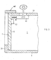
- Figur 3 einen Längsschnitt durch einen vorderen Teil einer anderen Kassette.
- Eine Kassette besteht im wesentlichen aus einen Innenraum 1 umschliessenden Wandungen 2, 3, 4, 5, von denen eine Vorderwand 6 aus einem eine Öffnung 7 des Innenraumes 1 abdekkenden Schiebedeckel 8 besteht und von denen eine weitere als ein Boden 9 ausgebildet ist, der über mindestens eine Halterung 10 an einer die Kassette tragenden Standfläche 11 befestigt ist.
- Der Boden 9 ist als eine rechteckige Stahlplatte ausgebildet und entlang seiner Längskanten mit Seitenwänden 13, 14 verbunden, die den Innenraum 1 in seinen Querrichtungen begrenzen und die einander planparallel verlaufen. In seinen Längsrichtungen wird der Innenraum 1 an seinem einen Ende 15 begrenzt von der Vorderwand 6 und an seinem dem einen Ende 15 abgewandten anderen Ende 16 von einer Rückwand 17. An seiner dem Boden 9 abgewandten Oberseite 18 erstreckt sich eine Deckplatte 19, die entlang ihrer den Seitenwänden 13,14 und der Rückwand 17 zugekehrten Kanten jeweils mit den Seitenwänden 13, 14 und der Rückwand 17 verbunden ist. Die Kassette besteht im wesentlichen aus zwei U-Profilen 20, 21, die entlang ihrer einander zugekehrten Schenkel 22, 23 miteinander verbunden sind. Ein oberes U-Profil 20 ist mit einem Joch 24 versehen, das die Deckplatte 19 ausbildet. Ein unteres U- Profil 21 weist ein Joch 25 auf, das den Boden 9 bildet. Die Joche 24, 25 weisen in ihren Querrichtungen im wesentlichen gleiche Abmessungen auf und sind jeweils rechtwinklig mit ihren Schenkeln 22, 23 verbunden. Die an dem oberen U-Profil 20 vorgesehenen Schenkel 22 sind kürzer als die an dem unteren U-Profil 21 vorgesehenen Schenkel 23. Die Längen der Schenkel 22, 23 sind in der Weise aufeinander abgestimmt, dass die jeweils einander zugekehrte Schenkel 22, 23 verbindenden Schweissnähte 26 der Deckplatte 19 benachbart verlaufen.
- Die Rückwand 17 ist aus einer Verlängerung 27 des Joches 24 gebildet, die in Richtung auf den Boden 9 abgewinkelt und mit diesem und den Seitenwänden 13, 14 an jeweils einander zugekehrten Kanten verbunden ist. Das Joch 25 und die Schenkel 23 des unteren U- Profiles 21 weisen der Rückwand 17 abgewandte Randbereiche 28, 29 auf, die in jeweils aufeinander zu verlaufende Richtungen von dem Joch 25 und den Schenkeln 23 abgewinkelt sind. Die Randbereiche 28, 29 bilden Führungsleisten 30, 31, 32 aus, die die als Schiebedeckel 8 ausgebildete Vorderwand 6 führend beaufschlagen. Mit seiner den Führungsleisten 30, 31, 32 abgekehrten Oberfläche stützt sich der Schiebedeckel 8 an Führungsstegen 33, 34 ab, die an den Schenkeln 23 im Bereich der Öffnung 7 vorgesehen sind. Die Führungsstege 33, 34 verlaufen den an den Schenkeln 23 des unteren U-Profiles 21 angeordneten Führungsleisten 31,32 parallel und verengen die Öffnung 7 um ein geringes Mass.
- Der Schiebedeckel 8 ist mit einer Anschlagleiste 35 versehen, die im Bereich einer Kante des Schiebedeckels 8 vorgesehen ist. Die Anschlagleiste 35 beaufschlagt bei geschlossener Öffnung 7 die Deckplatte 19 an ihrer dem Innenraum 1 abgewandten Oberseite 37. Der Schiebedeckel 8 ist mit einer Ausnehmung 38 versehen, die als ein benachbart zur Anschlagleiste 35 und dieser parallel verlaufender Schlitz ausgebildet ist, der von einem Schliessglied 39 eines Schlosses 40 beaufschlagt wird, das benachbart zur Öffnung 7 an der Deckplatte 19 angeordnet ist. Das Schliessglied 39 ist als ein im Innenraum 1 schwenkbar gelagerter Schwenkarm ausgebildet, der bei geschlossener Stellung in die Ausnehmung 38 hineinragt und den Schiebedeckel in einer geschlossenen Stellung sichert. An seiner der Anschlagleiste 35 abgewandten Seite ist der Schiebedeckel 8 mit einer Griffleiste 41 versehen, die als ein die Ausnehmung 38 vollständig überdeckender Steg ausgebildet ist.
- Das Schloss 40 ist auf der dem Innenraum zugewandten Seite der Deckplatte 19 befestigt und weist einen grösseren Durchmesser auf als das Loch in der Deckplatte 19, durch das der Schlüssel geführt werden kann.
- Auf der dem Innenraum zugewandten Seite des Schiebedeckels 8 kann ein Klotz 52 (Fig. 3) aufgeschweisst sein, und zwar im Abstand der Breite des Schliessglieds 39 zu der dem Innenraum 1 zugewandten Seite der umschliessenden Wandung 3, wobei die Anschlagleiste 35 als Deckelauflage ausgebildet ist, die mit dem Schiebedeckel 8 zusammen einen T-förmigen Querschnitt bildet und mit ihrer vom Schlüssel abgewandten Vorderkante bündig mit den Randbereichen 28, 29 abschliesst.
- Der Boden 9 ist mit vier Bohrungen 42 versehen, durch die jeweils eine eine Halterung 10 ausbildende Schraube 43 hindurchragt, mit der die Kassette an der Standfläche 11 befestigt ist. Die Schraube 43 durchdringt Bohrungen 45 der Standfläche 11 und Ausnehmungen 46, die in einer Verstärkungsplatte 47 vorgesehen sind, die sich auf einer dem Boden 9 abgewandten Seite der Standfläche 11 erstreckt. Die Verstärkungsplatte 47 ist als eine im wesentlichen quadratische Stahlplatte ausgebildet, an deren der Standfläche 11 abgewandten Oberfläche 48 sich die Köpfe 44 der Schrauben 43 abstützen. Die Köpfe 44 sind als Linsenköpfe ausgebildet und in Richtung auf den Boden 9 mit Vierkantanschlägen versehen, an die die Ausnehmungen 46 angepasst sind. Die Vierkantanschläge 49 bilden gemeinsam mit den Ausnehmungen 46 formschlüssige Verbindungen zwischen den Schrauben 43 und der Verstärkungsplatte 47.
- Mit ihren den Köpfen 44 abgewandten Enden 50 ragen die Schrauben 43 in den Innenraum 1 hinein und sind dort mit entsprechenden Muttern 51 versehen, die den Boden 9 in Richtung auf die Standfläche 11 festspannend beaufschlagen. Die Muttern 51 können auf den Schrauben 43 gesichert sein. Sie können selbsthemmend auf den Schrauben 43 gelagert sein oder mit einer Schweissstelle an den Schrauben 43 befestigt sein.
- Die Kassette kann an einer sie tragenden Standfläche 11 befestigt werden. Zu diesem Zwecke wird die Standfläche 11 mit Bohrungen 45 versehen, deren Abmessungen und Abstände zueinander im wesentlichen denjenigen der in dem Boden 9 vorgesehenen Bohrungen 42 entsprechen. An ihrer dem Boden 9 abgewandten Seite wird die Standfläche 11 mit der Verstärkungsplatte 47 abgedeckt und die Schrauben 43 werden durch die Ausnehmungen 46 und die Bohrungen 45 hindurchgeschoben, so dass ihre Enden 50 in den Innenraum 1 hineinragen und dort mit den Muttern 51 versehen sind. Die Schrauben 43 sind mit ihren Vierkantanschlägen 49 in den Ausnehmungen 46 gegen Drehbewegungen gesichert. Nach ihrer Befestigung stellt die Kassette einen gegen Diebstahl sehr gut gesicherten Behälter dar, der jederzeit leicht zugänglich ist. Der Schiebedeckel 8 ist bezogen auf die Standfläche 11 im wesentlichen in vertikalen Richtungen verschieblich gelagert, so dass der Innenraum 1 leicht zugänglich ist, wenn der Schiebedeckel 8 zwischen die Führungsleisten 30, 31, 32 einerseits und die Führungsstege 33, 34 andererseits geschoben wird, bis seine Anschlagleiste 35 die Oberseite 37 der Deckplatte 19 beaufschlagt. Durch Verschwenken des Schliessgliedes 39 des Schlosses 40 in Richtung auf den Schiebedeckel 8 kann das Schliessglied 39 in die Ausnehmung 38 hineinragen und dort den Schiebedeckel 8 festlegen, so dass der Innenraum 1 für Unbefugte unzugänglich ist.
- Die Kassette besteht im wesentlichen aus Stahl. Die Halterung 10 kann aus mindestens einer Schraube 43 bestehen. Es ist möglich, den Boden 9 der Kassette in der Weise an der Standfläche 11 zu befestigen, dass sich an dieser unmittelbar die Köpfe 44 der Schrauben 43 abstützen.
Claims (14)
Priority Applications (1)
| Application Number | Priority Date | Filing Date | Title |
|---|---|---|---|
| AT85900647T ATE40173T1 (de) | 1984-01-30 | 1985-01-29 | Kassette zum aufbewahren von wertgegenstaenden. |
Applications Claiming Priority (2)
| Application Number | Priority Date | Filing Date | Title |
|---|---|---|---|
| DE3403061 | 1984-01-30 | ||
| DE19843403061 DE3403061A1 (de) | 1984-01-30 | 1984-01-30 | Kassette zum aufbewahren von wertgegenstaenden |
Publications (2)
| Publication Number | Publication Date |
|---|---|
| EP0170667A1 EP0170667A1 (de) | 1986-02-12 |
| EP0170667B1 true EP0170667B1 (de) | 1989-01-18 |
Family
ID=6226234
Family Applications (1)
| Application Number | Title | Priority Date | Filing Date |
|---|---|---|---|
| EP85900647A Expired EP0170667B1 (de) | 1984-01-30 | 1985-01-29 | Kassette zum aufbewahren von wertgegenständen |
Country Status (3)
| Country | Link |
|---|---|
| EP (1) | EP0170667B1 (de) |
| DE (2) | DE3403061A1 (de) |
| WO (1) | WO1985003324A1 (de) |
Families Citing this family (5)
| Publication number | Priority date | Publication date | Assignee | Title |
|---|---|---|---|---|
| GB8708893D0 (en) * | 1987-04-14 | 1987-05-20 | Thompson J | Security devices for safes |
| JPH074295B2 (ja) * | 1990-11-13 | 1995-01-25 | 信世 酒井 | パーソナルシークレットケース |
| US5783532A (en) * | 1993-06-17 | 1998-07-21 | Allergan | Enzyme compositions and methods for contact lens cleaning |
| IL109705A (en) * | 1993-06-17 | 1998-07-15 | Allergan Inc | Enzyme compositions and methods for contact lens cleaning |
| US10540859B2 (en) | 2016-07-28 | 2020-01-21 | Farrish B. Sullivan | ATM/vending machine armor |
Family Cites Families (5)
| Publication number | Priority date | Publication date | Assignee | Title |
|---|---|---|---|---|
| DE930615C (de) * | 1954-03-09 | 1955-07-21 | Heinz Sieprath | Tresor fuer Kraftfahrzeuge |
| US3481288A (en) * | 1968-04-05 | 1969-12-02 | Walter Teleky | Wall safe |
| GB1286106A (en) * | 1969-09-08 | 1972-08-23 | Heinz Gerd Heinrichs | Improvements in or relating to strong-boxes |
| FR2225603A1 (en) * | 1973-04-13 | 1974-11-08 | Prevenco Ltd | Remote control safe deposit box and bolt - is suspended below counter and has electrically operated sliding door |
| US4278033A (en) * | 1979-03-09 | 1981-07-14 | Bona Fide Factory Products, Inc. | Tamper resistant safe |
-
1984
- 1984-01-30 DE DE19843403061 patent/DE3403061A1/de not_active Ceased
-
1985
- 1985-01-29 WO PCT/DE1985/000022 patent/WO1985003324A1/de not_active Ceased
- 1985-01-29 DE DE8585900647T patent/DE3567689D1/de not_active Expired
- 1985-01-29 EP EP85900647A patent/EP0170667B1/de not_active Expired
Also Published As
| Publication number | Publication date |
|---|---|
| DE3567689D1 (en) | 1989-02-23 |
| EP0170667A1 (de) | 1986-02-12 |
| DE3403061A1 (de) | 1985-08-01 |
| WO1985003324A1 (en) | 1985-08-01 |
Similar Documents
| Publication | Publication Date | Title |
|---|---|---|
| DE4329997B4 (de) | Einrichtung zum Ent- und Verriegeln von zumindest zwei mit Abstand zueinander angeordneten, schwenkbaren Hauben eines Kraftfahrzeuges | |
| DE2742995A1 (de) | Ausschwingbare schiebetuer fuer fahrzeuge | |
| DE3816765A1 (de) | Eingriffsichere vorhaengeschloss-beschlaganordnung | |
| DE60028238T2 (de) | Zusammenfaltbarer sicherheitsbehälter | |
| DE3020064C2 (de) | ||
| EP0934848A2 (de) | Verriegelungsvorrichtung für Container-Transportfahrzeuge | |
| WO1985003324A1 (en) | Box for keeping valuable articles | |
| EP0181357A1 (de) | Sicherheitstransportbehälter | |
| DE2507627A1 (de) | Behaelter | |
| DE60225324T2 (de) | Behälterverriegelungsvorrichtung | |
| DE3204216C2 (de) | ||
| DE6901382U (de) | Stangenschloss | |
| DE2900632A1 (de) | Schlosseinheit | |
| DE10129162B4 (de) | Schloß für Ganzglastüren | |
| DE3642092A1 (de) | Staukasten | |
| DE4240418C2 (de) | Revisionsabdeckung | |
| EP1398217A2 (de) | Deckel für ein Ablagefach in einem Fahrzeug | |
| EP0916787A1 (de) | Abstellbox | |
| DE2611141A1 (de) | Aufbau fuer lastfahrzeuge | |
| EP0887250A2 (de) | Halterung für Behälter im allgemeinen und Aktenkoffer im besonderen, geeignet für Motorräder und dergleichen | |
| CH692707A5 (de) | Sicherheitsverschluss eines begeh- oder befahrbaren Deckels. | |
| DE2613278C2 (de) | Schrank für Einbautresor | |
| DE3126666A1 (de) | Schloss | |
| DE1939313U (de) | Fensterabdeckungsvorrichtung. | |
| EP4275933A1 (de) | Aufbau eines nutzfahrzeugs mit rückwandtüren |
Legal Events
| Date | Code | Title | Description |
|---|---|---|---|
| PUAI | Public reference made under article 153(3) epc to a published international application that has entered the european phase |
Free format text: ORIGINAL CODE: 0009012 |
|
| AK | Designated contracting states |
Designated state(s): AT BE CH DE FR GB LI LU NL SE |
|
| 17P | Request for examination filed |
Effective date: 19860201 |
|
| 17Q | First examination report despatched |
Effective date: 19870119 |
|
| GRAA | (expected) grant |
Free format text: ORIGINAL CODE: 0009210 |
|
| AK | Designated contracting states |
Kind code of ref document: B1 Designated state(s): AT BE CH DE FR GB LI LU NL SE |
|
| PG25 | Lapsed in a contracting state [announced via postgrant information from national office to epo] |
Ref country code: SE Effective date: 19890118 Ref country code: NL Effective date: 19890118 Ref country code: GB Free format text: LAPSE BECAUSE OF NON-PAYMENT OF DUE FEES Effective date: 19890118 Ref country code: FR Free format text: THE PATENT HAS BEEN ANNULLED BY A DECISION OF A NATIONAL AUTHORITY Effective date: 19890118 Ref country code: BE Effective date: 19890118 |
|
| REF | Corresponds to: |
Ref document number: 40173 Country of ref document: AT Date of ref document: 19890215 Kind code of ref document: T |
|
| PG25 | Lapsed in a contracting state [announced via postgrant information from national office to epo] |
Ref country code: AT Effective date: 19890129 |
|
| PG25 | Lapsed in a contracting state [announced via postgrant information from national office to epo] |
Ref country code: LU Free format text: LAPSE BECAUSE OF NON-PAYMENT OF DUE FEES Effective date: 19890131 Ref country code: LI Effective date: 19890131 Ref country code: CH Effective date: 19890131 |
|
| REF | Corresponds to: |
Ref document number: 3567689 Country of ref document: DE Date of ref document: 19890223 |
|
| EN | Fr: translation not filed | ||
| NLV1 | Nl: lapsed or annulled due to failure to fulfill the requirements of art. 29p and 29m of the patents act | ||
| GBV | Gb: ep patent (uk) treated as always having been void in accordance with gb section 77(7)/1977 [no translation filed] | ||
| REG | Reference to a national code |
Ref country code: CH Ref legal event code: PL |
|
| REG | Reference to a national code |
Ref country code: CH Ref legal event code: AUV Free format text: DAS OBENGENANNTE PATENT IST, MANGELS BEZAHLUNG DER 5. JAHRESGEBUEHR GELOESCHT WORDEN. |
|
| PLBE | No opposition filed within time limit |
Free format text: ORIGINAL CODE: 0009261 |
|
| STAA | Information on the status of an ep patent application or granted ep patent |
Free format text: STATUS: NO OPPOSITION FILED WITHIN TIME LIMIT |
|
| 26N | No opposition filed | ||
| PGFP | Annual fee paid to national office [announced via postgrant information from national office to epo] |
Ref country code: DE Payment date: 19930419 Year of fee payment: 9 |
|
| PG25 | Lapsed in a contracting state [announced via postgrant information from national office to epo] |
Ref country code: DE Effective date: 19941001 |