EP0170128A2 - Silo pour matières en vrac à chambre de décharge désaérée - Google Patents
Silo pour matières en vrac à chambre de décharge désaérée Download PDFInfo
- Publication number
- EP0170128A2 EP0170128A2 EP85108672A EP85108672A EP0170128A2 EP 0170128 A2 EP0170128 A2 EP 0170128A2 EP 85108672 A EP85108672 A EP 85108672A EP 85108672 A EP85108672 A EP 85108672A EP 0170128 A2 EP0170128 A2 EP 0170128A2
- Authority
- EP
- European Patent Office
- Prior art keywords
- silo
- float
- outlet chamber
- cage
- bulk material
- Prior art date
- Legal status (The legal status is an assumption and is not a legal conclusion. Google has not performed a legal analysis and makes no representation as to the accuracy of the status listed.)
- Withdrawn
Links
Images

Classifications
-
- B—PERFORMING OPERATIONS; TRANSPORTING
- B65—CONVEYING; PACKING; STORING; HANDLING THIN OR FILAMENTARY MATERIAL
- B65D—CONTAINERS FOR STORAGE OR TRANSPORT OF ARTICLES OR MATERIALS, e.g. BAGS, BARRELS, BOTTLES, BOXES, CANS, CARTONS, CRATES, DRUMS, JARS, TANKS, HOPPERS, FORWARDING CONTAINERS; ACCESSORIES, CLOSURES, OR FITTINGS THEREFOR; PACKAGING ELEMENTS; PACKAGES
- B65D88/00—Large containers
- B65D88/54—Large containers characterised by means facilitating filling or emptying
- B65D88/72—Fluidising devices
-
- Y—GENERAL TAGGING OF NEW TECHNOLOGICAL DEVELOPMENTS; GENERAL TAGGING OF CROSS-SECTIONAL TECHNOLOGIES SPANNING OVER SEVERAL SECTIONS OF THE IPC; TECHNICAL SUBJECTS COVERED BY FORMER USPC CROSS-REFERENCE ART COLLECTIONS [XRACs] AND DIGESTS
- Y10—TECHNICAL SUBJECTS COVERED BY FORMER USPC
- Y10T—TECHNICAL SUBJECTS COVERED BY FORMER US CLASSIFICATION
- Y10T137/00—Fluid handling
- Y10T137/2931—Diverse fluid containing pressure systems
- Y10T137/3003—Fluid separating traps or vents
- Y10T137/3084—Discriminating outlet for gas
- Y10T137/309—Fluid sensing valve
- Y10T137/3099—Float responsive
Definitions
- the invention relates to a bulk goods silo with an outlet chamber, from the upper part of which a generally open vent line is provided, which is equipped with a closure member to protect against flooding.
- vent line of silo emptying chambers is essentially led vertically upwards, so that possibly penetrating bulk goods can fall out again without clogging the vent line downwards (DE-OS 26 19 993).
- vertical vent lines can generally only on the Silo outer wall are arranged so that they are only suitable for venting an outlet chamber arranged centrally on the silo bottom if a lateral auxiliary chamber is provided between this central chamber and the vent line arranged on the outside of the silo wall (DE-PS 26 57 597).
- the invention has for its object to provide an inexpensive, reliable and maintenance-friendly device for protecting a ventilation line that does not exclusively extend vertically.
- the closure member is designed as a float valve, the float cage of which is equipped with a ventilation device in the area below the float.
- Float valves are known in the field of liquid delivery, and also in the form preferred by the invention, in which the float valve opening is above of the float forming the valve body is arranged. It is also known that bulk material can be brought into a liquid-like state by aeration and that therefore some of the elements known from the field of liquid production focus on the fluidized in the production. Have bulk goods transferred. Nevertheless, the use of a float valve to solve the problem on which the invention is based was not obvious. The analogy between the conveying of liquids and the conveying of fluidized bulk goods always fails when the fluidized state of the bulk goods is not ensured under all operating conditions and when the proper functioning of the organ under consideration appears to be jeopardized by the occurrence of unfluidized bulk goods.
- the ventilation device is expediently designed as a porous surface which is provided on the upper side by the closed lower surface and through which compressed air is constantly pressed and which is laterally free for the discharge of the fluidized material thereon.
- the ventilation device according to the invention is preferably constantly pressurized with compressed air, even if there is no acute risk of flooding.
- the resulting additional air requirement is negligible compared to that of the other ventilation devices in a silo.
- the hollow cone-shaped outlet chamber 4 is arranged on the silo floor 3, in which the outlet 5 is arranged in the lower center, to which the outlet line 6 is connected, for example as a pneumatic conveyor trough.
- the bottom of the outlet chamber is equipped with porous loosening elements in the usual way, which are fed from a compressor 7 via a line 8.
- a ventilation line 10 leads to the outlet line 6.
- the upper end of the ventilation line 10 is curved vertically downward at 11 to form the inlet opening of the ventilation line delimited by the circular edge 12.
- the edge 12 is provided with a rubber-elastic sealing ring for the purpose of better sealing in cooperation with the valve body.
- the float cage 13 which is formed from a plurality of cage bars 14 and a cage base 15 attached thereto, is fastened coaxially and vertically to the pipe section 11 of the ventilation pipe 10.
- the ball 16 within the cage is the ball 16 as a float and valve body, the diameter of which is not significantly less than the free cage diameter in its upper area, while it continues to widen downwards.
- the ball 16 is shown with solid lines in the raised closed position and with dash-dotted lines in its rest position.
- the cage bottom consists of an upper porous plate 17 and a compressed air supply chamber 18 which is tightly connected to the edge thereof, which in turn is connected via line 19 to the blower 7 and is preferably constantly pressurized with compressed air by the latter.
- the ball 16 lies on the plate 15. If the material rises in the chamber 4 to the upper space 9, it penetrates into the cage 13 from the side and lifts the ball 16 until it cooperates with the inlet opening whose edge 12 closes. The material that has accumulated beneath it in the cage 13 can flow off again after the material level has dropped due to the ventilation through the porous layer 17 even if it had not previously been sufficiently fluidized.
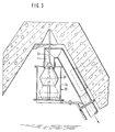
- the embodiment according to FIG. 3 differs from that according to FIG. 2 in that the valve body 20 is double-tapered about a vertical axis and is guided vertically displaceably with a guide rod 21 in guides, not shown, within the pipe section 11.
- the cage has no management tasks, so that it can have any external shape and the distances between the cage bars 14 can be greater than the diameter of the valve body.
- the plate 15 is substantially larger in diameter than the valve body 16 or 20, so that it offers the valve arrangement protection from the material coming in from below in such a way that spilling of the arrangement through less fluidized material is not possible . Rather, this is forced to enter the valve arrangement from the side, thereby calming and at the same time loosely, so that there is both a greater probability that the valve body is still adequately inflated even under unfavorable circumstances, and the pneumatic loosening of the in the Cage penetrated by the material air supplied to the porous layer 17 is guaranteed for the purpose of this material running off.
Applications Claiming Priority (2)
| Application Number | Priority Date | Filing Date | Title |
|---|---|---|---|
| DE3428715A DE3428715A1 (de) | 1984-08-03 | 1984-08-03 | Schuettgutsilo mit einer entluefteten auslasskammer |
| DE3428715 | 1984-08-03 |
Publications (2)
| Publication Number | Publication Date |
|---|---|
| EP0170128A2 true EP0170128A2 (fr) | 1986-02-05 |
| EP0170128A3 EP0170128A3 (fr) | 1987-06-10 |
Family
ID=6242323
Family Applications (1)
| Application Number | Title | Priority Date | Filing Date |
|---|---|---|---|
| EP85108672A Withdrawn EP0170128A3 (fr) | 1984-08-03 | 1985-07-11 | Silo pour matières en vrac à chambre de décharge désaérée |
Country Status (3)
| Country | Link |
|---|---|
| US (1) | US4630531A (fr) |
| EP (1) | EP0170128A3 (fr) |
| DE (1) | DE3428715A1 (fr) |
Families Citing this family (4)
| Publication number | Priority date | Publication date | Assignee | Title |
|---|---|---|---|---|
| DE3743637A1 (de) * | 1987-12-22 | 1989-07-06 | Krupp Polysius Ag | Silo fuer schuettgut |
| US6016828A (en) * | 1999-01-04 | 2000-01-25 | Machledt; Charles G. | Vault vent having dual ball water seal |
| US6848465B1 (en) | 2002-04-17 | 2005-02-01 | Robert H. Wager Co., Inc. | Dual-action vent check valve |
| KR20160041468A (ko) * | 2014-10-07 | 2016-04-18 | 강은진 | 방수 기능을 갖는 공조 장치 |
Citations (3)
| Publication number | Priority date | Publication date | Assignee | Title |
|---|---|---|---|---|
| DE2657597A1 (de) * | 1976-12-18 | 1978-06-22 | Peters Ag Claudius | Schuettgutsilo mit mischkammer |
| DE2849014B1 (de) * | 1978-11-11 | 1980-05-14 | Peters Ag Claudius | Schuettgutsilo mit pneumatischer Entleerung und mit einer entluefteten Auslasskammer |
| DE2619993B2 (de) * | 1976-05-06 | 1981-02-12 | Claudius Peters Ag, 2000 Hamburg | Verfahren zur Entnahme von Schüttgut aus einem bodenbelüfteten Silo sowie Entnahmevorrichtung zur Durchführung des Verfahrens |
Family Cites Families (9)
| Publication number | Priority date | Publication date | Assignee | Title |
|---|---|---|---|---|
| DE7432854U (de) * | 1975-07-10 | Henkel & Cie Gmbh | Be- und Entlüftungseinrichtung für Behälter | |
| US2757752A (en) * | 1952-07-30 | 1956-08-07 | Jack W Kaufman | Valve assembly for drain conduits |
| US2843146A (en) * | 1955-11-28 | 1958-07-15 | Louis A Kirschner | Drain trap and means for locking same to the waste pipe |
| US2871875A (en) * | 1956-11-19 | 1959-02-03 | Harold E Dale | Valve mounting means |
| US3196774A (en) * | 1962-06-27 | 1965-07-27 | Behlen Mfg Company Inc | Method of and means for circulating air within closed buildings |
| CH492621A (de) * | 1969-12-11 | 1970-06-30 | Alusuisse | Entleerungsvorrichtung an Silos mit flachem Boden |
| US4088149A (en) * | 1976-05-20 | 1978-05-09 | Logsdon Duane D | Check valve structure for use in drains |
| US4129069A (en) * | 1977-08-17 | 1978-12-12 | Thompson Andy L | Breather bag apparatus |
| DE7935648U1 (de) * | 1979-12-18 | 1980-03-20 | Krupp Polysius Ag, 4720 Beckum | Silo zum pneumatischen mischen und homogenisieren von feingut |
-
1984
- 1984-08-03 DE DE3428715A patent/DE3428715A1/de not_active Withdrawn
-
1985
- 1985-07-11 EP EP85108672A patent/EP0170128A3/fr not_active Withdrawn
- 1985-07-30 US US06/760,467 patent/US4630531A/en not_active Expired - Fee Related
Patent Citations (3)
| Publication number | Priority date | Publication date | Assignee | Title |
|---|---|---|---|---|
| DE2619993B2 (de) * | 1976-05-06 | 1981-02-12 | Claudius Peters Ag, 2000 Hamburg | Verfahren zur Entnahme von Schüttgut aus einem bodenbelüfteten Silo sowie Entnahmevorrichtung zur Durchführung des Verfahrens |
| DE2657597A1 (de) * | 1976-12-18 | 1978-06-22 | Peters Ag Claudius | Schuettgutsilo mit mischkammer |
| DE2849014B1 (de) * | 1978-11-11 | 1980-05-14 | Peters Ag Claudius | Schuettgutsilo mit pneumatischer Entleerung und mit einer entluefteten Auslasskammer |
Also Published As
| Publication number | Publication date |
|---|---|
| DE3428715A1 (de) | 1986-02-13 |
| EP0170128A3 (fr) | 1987-06-10 |
| US4630531A (en) | 1986-12-23 |
Similar Documents
| Publication | Publication Date | Title |
|---|---|---|
| DE2205716A1 (de) | Aufgabevorrichtung für Schüttgut | |
| WO2001037980A2 (fr) | Dispositif de revetement de particules | |
| CH671211A5 (fr) | ||
| DE4130056C2 (de) | Einrichtung zum Tränken von Geflügel und Kleintieren | |
| DE3245943C2 (de) | Auslaßventil zur schaumarmen Abgabe loser Frischmilch in abgemessenen Mengen an den Verbraucher | |
| EP0170128A2 (fr) | Silo pour matières en vrac à chambre de décharge désaérée | |
| EP0001422B1 (fr) | Dispositif pour le déversement pneumatique de particules fines d'un récipient et procédé pour sa mise en oeuvre | |
| DE3022346C2 (de) | Mischsilo für Schüttgut | |
| DE2657597C2 (de) | Schüttgutsilo mit Homogenisierkammer | |
| DE2914007C3 (de) | Vorrichtung zum Trennen eines Gemisches von Flüssigkeiten verschiedener, spezifischer Gewichte, z.B. Öl und Wasser | |
| DE1129892B (de) | Entleerungsvorrichtung fuer flachboedige Silos fuer staubfoermiges oder feinkoerniges Gut | |
| DE2914016C2 (fr) | ||
| WO1984004964A1 (fr) | Dispositif de dosage de liquides | |
| DE3822555C2 (fr) | ||
| DE2530270A1 (de) | Vorrichtung zur kontaktgabe zwischen einer fluessigkeit und einem gas | |
| DE7531503U (de) | Entleerungsvorrichtung an flachboedigen schuettgutsilos | |
| DE1268062B (de) | Vorrichtung zum Entleeren einer Silozelle fuer pneumatisch in fliessbaren Zustand versetzbare Schuettgueter | |
| DE4410568C1 (de) | Dosiervorrichtung | |
| DE2154006C3 (de) | Mischsilo für pulverförmiges Material | |
| DE3024327C2 (de) | Trichterförmiger Austrag für Transportschüttgutbehälter | |
| DE482706C (de) | Lueftungs- und Entleerungsvorrichtung fuer Getreidesilos | |
| DE4328071A1 (de) | Vorrichtung zur Entnahme von schwerfließenden Schüttgütern aus einem Silo | |
| DE7132212U (de) | Belüftbarer Behälterboden zum pneumatischen Austragen von trockenem Feingut aus einem Behälter | |
| DE2849014B1 (de) | Schuettgutsilo mit pneumatischer Entleerung und mit einer entluefteten Auslasskammer | |
| DE3523256A1 (de) | Vorrichtung zur pneumatischen foerderung von feingut |
Legal Events
| Date | Code | Title | Description |
|---|---|---|---|
| PUAI | Public reference made under article 153(3) epc to a published international application that has entered the european phase |
Free format text: ORIGINAL CODE: 0009012 |
|
| AK | Designated contracting states |
Designated state(s): DE FR GB IT |
|
| PUAL | Search report despatched |
Free format text: ORIGINAL CODE: 0009013 |
|
| AK | Designated contracting states |
Kind code of ref document: A3 Designated state(s): DE FR GB IT |
|
| RHK1 | Main classification (correction) |
Ipc: B65D 88/72 |
|
| 17P | Request for examination filed |
Effective date: 19870730 |
|
| 17Q | First examination report despatched |
Effective date: 19880505 |
|
| RAP1 | Party data changed (applicant data changed or rights of an application transferred) |
Owner name: CLAUDIUS PETERS AKTIENGESELLSCHAFT |
|
| STAA | Information on the status of an ep patent application or granted ep patent |
Free format text: STATUS: THE APPLICATION IS DEEMED TO BE WITHDRAWN |
|
| 18D | Application deemed to be withdrawn |
Effective date: 19881025 |
|
| RIN1 | Information on inventor provided before grant (corrected) |
Inventor name: KRAUSS, WERNER |