EP0170128A2 - Silo for bulk material having an air vent outlet chamber - Google Patents
Silo for bulk material having an air vent outlet chamber Download PDFInfo
- Publication number
- EP0170128A2 EP0170128A2 EP85108672A EP85108672A EP0170128A2 EP 0170128 A2 EP0170128 A2 EP 0170128A2 EP 85108672 A EP85108672 A EP 85108672A EP 85108672 A EP85108672 A EP 85108672A EP 0170128 A2 EP0170128 A2 EP 0170128A2
- Authority
- EP
- European Patent Office
- Prior art keywords
- silo
- float
- outlet chamber
- cage
- bulk material
- Prior art date
- Legal status (The legal status is an assumption and is not a legal conclusion. Google has not performed a legal analysis and makes no representation as to the accuracy of the status listed.)
- Withdrawn
Links
Images

Classifications
-
- B—PERFORMING OPERATIONS; TRANSPORTING
- B65—CONVEYING; PACKING; STORING; HANDLING THIN OR FILAMENTARY MATERIAL
- B65D—CONTAINERS FOR STORAGE OR TRANSPORT OF ARTICLES OR MATERIALS, e.g. BAGS, BARRELS, BOTTLES, BOXES, CANS, CARTONS, CRATES, DRUMS, JARS, TANKS, HOPPERS, FORWARDING CONTAINERS; ACCESSORIES, CLOSURES, OR FITTINGS THEREFOR; PACKAGING ELEMENTS; PACKAGES
- B65D88/00—Large containers
- B65D88/54—Large containers characterised by means facilitating filling or emptying
- B65D88/72—Fluidising devices
-
- Y—GENERAL TAGGING OF NEW TECHNOLOGICAL DEVELOPMENTS; GENERAL TAGGING OF CROSS-SECTIONAL TECHNOLOGIES SPANNING OVER SEVERAL SECTIONS OF THE IPC; TECHNICAL SUBJECTS COVERED BY FORMER USPC CROSS-REFERENCE ART COLLECTIONS [XRACs] AND DIGESTS
- Y10—TECHNICAL SUBJECTS COVERED BY FORMER USPC
- Y10T—TECHNICAL SUBJECTS COVERED BY FORMER US CLASSIFICATION
- Y10T137/00—Fluid handling
- Y10T137/2931—Diverse fluid containing pressure systems
- Y10T137/3003—Fluid separating traps or vents
- Y10T137/3084—Discriminating outlet for gas
- Y10T137/309—Fluid sensing valve
- Y10T137/3099—Float responsive
Definitions
- the invention relates to a bulk goods silo with an outlet chamber, from the upper part of which a generally open vent line is provided, which is equipped with a closure member to protect against flooding.
- vent line of silo emptying chambers is essentially led vertically upwards, so that possibly penetrating bulk goods can fall out again without clogging the vent line downwards (DE-OS 26 19 993).
- vertical vent lines can generally only on the Silo outer wall are arranged so that they are only suitable for venting an outlet chamber arranged centrally on the silo bottom if a lateral auxiliary chamber is provided between this central chamber and the vent line arranged on the outside of the silo wall (DE-PS 26 57 597).
- the invention has for its object to provide an inexpensive, reliable and maintenance-friendly device for protecting a ventilation line that does not exclusively extend vertically.
- the closure member is designed as a float valve, the float cage of which is equipped with a ventilation device in the area below the float.
- Float valves are known in the field of liquid delivery, and also in the form preferred by the invention, in which the float valve opening is above of the float forming the valve body is arranged. It is also known that bulk material can be brought into a liquid-like state by aeration and that therefore some of the elements known from the field of liquid production focus on the fluidized in the production. Have bulk goods transferred. Nevertheless, the use of a float valve to solve the problem on which the invention is based was not obvious. The analogy between the conveying of liquids and the conveying of fluidized bulk goods always fails when the fluidized state of the bulk goods is not ensured under all operating conditions and when the proper functioning of the organ under consideration appears to be jeopardized by the occurrence of unfluidized bulk goods.
- the ventilation device is expediently designed as a porous surface which is provided on the upper side by the closed lower surface and through which compressed air is constantly pressed and which is laterally free for the discharge of the fluidized material thereon.
- the ventilation device according to the invention is preferably constantly pressurized with compressed air, even if there is no acute risk of flooding.
- the resulting additional air requirement is negligible compared to that of the other ventilation devices in a silo.
- the hollow cone-shaped outlet chamber 4 is arranged on the silo floor 3, in which the outlet 5 is arranged in the lower center, to which the outlet line 6 is connected, for example as a pneumatic conveyor trough.
- the bottom of the outlet chamber is equipped with porous loosening elements in the usual way, which are fed from a compressor 7 via a line 8.
- a ventilation line 10 leads to the outlet line 6.
- the upper end of the ventilation line 10 is curved vertically downward at 11 to form the inlet opening of the ventilation line delimited by the circular edge 12.
- the edge 12 is provided with a rubber-elastic sealing ring for the purpose of better sealing in cooperation with the valve body.
- the float cage 13 which is formed from a plurality of cage bars 14 and a cage base 15 attached thereto, is fastened coaxially and vertically to the pipe section 11 of the ventilation pipe 10.
- the ball 16 within the cage is the ball 16 as a float and valve body, the diameter of which is not significantly less than the free cage diameter in its upper area, while it continues to widen downwards.
- the ball 16 is shown with solid lines in the raised closed position and with dash-dotted lines in its rest position.
- the cage bottom consists of an upper porous plate 17 and a compressed air supply chamber 18 which is tightly connected to the edge thereof, which in turn is connected via line 19 to the blower 7 and is preferably constantly pressurized with compressed air by the latter.
- the ball 16 lies on the plate 15. If the material rises in the chamber 4 to the upper space 9, it penetrates into the cage 13 from the side and lifts the ball 16 until it cooperates with the inlet opening whose edge 12 closes. The material that has accumulated beneath it in the cage 13 can flow off again after the material level has dropped due to the ventilation through the porous layer 17 even if it had not previously been sufficiently fluidized.
- the embodiment according to FIG. 3 differs from that according to FIG. 2 in that the valve body 20 is double-tapered about a vertical axis and is guided vertically displaceably with a guide rod 21 in guides, not shown, within the pipe section 11.
- the cage has no management tasks, so that it can have any external shape and the distances between the cage bars 14 can be greater than the diameter of the valve body.
- the plate 15 is substantially larger in diameter than the valve body 16 or 20, so that it offers the valve arrangement protection from the material coming in from below in such a way that spilling of the arrangement through less fluidized material is not possible . Rather, this is forced to enter the valve arrangement from the side, thereby calming and at the same time loosely, so that there is both a greater probability that the valve body is still adequately inflated even under unfavorable circumstances, and the pneumatic loosening of the in the Cage penetrated by the material air supplied to the porous layer 17 is guaranteed for the purpose of this material running off.
Abstract
Schüttgutsilo mit einer Auslaßkammer, von deren Oberraum eine im allgemeinen offene Entlüftungsleitung ausgeht, die zum Schutz vor Überflutung mit einem Verschlu-βorgan ausgestattet ist. Das Verschlußorgan ist als Schwimmerventil ausgebildet. Damit es nicht durch Verstopfung bzw. Überschüttung mit Schüttgut funktionsunfähig wird, ist sein Schwimmerkäfig im Bereich unterhalb des Schwimmers mit einer Belüftungseinrichtung ausgerüstet, die tellerförmig geschlossen ausgeführt sein kann, um das Ventil vor dem direkten Schwall des Guts zu schützen.
Description
Die Erfindung bezieht sich auf ein Schüttgutsilo mit einer Auslaßkammer, von deren Oberraum eine im allgemeinen offene Entlüftungsleitung ausgeht, die zum Schutz vor Überflutung mit einem Verschlußorgan ausgestattet ist.The invention relates to a bulk goods silo with an outlet chamber, from the upper part of which a generally open vent line is provided, which is equipped with a closure member to protect against flooding.
Meist wird die Entlüftungsleitung von Siloentleerungskammern im wesentlichen ausschließlich vertikal aufwärts geführt, damit möglicherweise eindringendes Schüttgut ohne Verstopfung der Entlüftungsleitung nach unten wieder herausfallen kann (DE-OS 26 19 993). Aus Stabilitätsgründen können derartige vertikale Entlüftungsleitungen im allgemeinen nur an der Siloaußenwand angeordnet werden, so daß sie sich zur Entlüftung einer mittig am Siloboden angeordneten Auslaßkammer nur dann eignen, wenn zwischen dieser mittigen Kammer und der an der Silowand außen angeordneten Entlüftungsleitung eine seitliche Hilfskammer vorgesehen ist (DE-PS 26 57 597). Den Aufwand für diese Hilfskammer kann man vermeiden, wenn man die Entlüftungsleitung nicht ausschließlich vertikal steigend, sondern in anderer Weise anordnet, insbesondere fallend zu einem unterhalb des Silobodens vorgesehenen Auslaßweg für das Gut (DE-AS 28 49 014), was aber zur Verhinderung einer Überflutung der Entlüftungsleitung und der damit verbundenen Verstopfungsgefahr ein Verschlußorgan in der Entlüftungsleitung erforderlich macht. In dem eingangs genannten bekannten_Fall wird dies zwangsweise gesteuert und jeweils dann geschlossen, wenn durch Schließung des Siloauslasses die Möglichkeit der überflutung der Entlüftungsleitung hervorgerufen wird. Jedoch sind die Verschlußorgane und die Einrichtungen zu ihrer aktiven Steuerung aufwendig.Most of the vent line of silo emptying chambers is essentially led vertically upwards, so that possibly penetrating bulk goods can fall out again without clogging the vent line downwards (DE-OS 26 19 993). For reasons of stability, such vertical vent lines can generally only on the Silo outer wall are arranged so that they are only suitable for venting an outlet chamber arranged centrally on the silo bottom if a lateral auxiliary chamber is provided between this central chamber and the vent line arranged on the outside of the silo wall (DE-PS 26 57 597). The effort for this auxiliary chamber can be avoided if the vent line is not arranged to rise exclusively vertically, but in a different way, in particular falling to an outlet path for the material provided below the silo floor (DE-AS 28 49 014), but this is to prevent a Flooding the vent line and the associated risk of clogging requires a closure member in the vent line. In the known case mentioned at the beginning, this is forcibly controlled and then closed in each case when the silo outlet closes the possibility of flooding the ventilation line. However, the closure members and the devices for their active control are expensive.
Der Erfindung liegt die Aufgabe zugrunde, eine unaufwendige, betriebssichere und wartungsfreundliche Einrichtung zum Schutz einer nicht ausschließlich vertikal steigend verlaufenden Entlüftungsleitung zu schaffen.The invention has for its object to provide an inexpensive, reliable and maintenance-friendly device for protecting a ventilation line that does not exclusively extend vertically.
Die erfindungsgemäße Lösung besteht darin, daß das Verschlußorgan als Schwimmerventil ausgebildet ist, dessen Schwimmerkäfig im Bereich unterhalb des Schwimmers mit einer Belüftungseinrichtung ausgerüstet ist.The solution according to the invention is that the closure member is designed as a float valve, the float cage of which is equipped with a ventilation device in the area below the float.
Schwimmerventile sind auf dem Gebiet der Flüssigkeitsförderung bekannt, und zwar auch in der von der Erfindung bevorzugten Form, bei welcher die Schwimmerventilöffnung oberhalb des den Ventilkörper bildenden Schwimmers angeordnet ist. Es ist auch bekannt, daß Schüttgut sich durch Belüftung in einen flüssigkeitsähnlichen Zustand versetzen läßt und daß daher manche von dem Gebiet der Flüssigkeitsförderung bekannten Elemente sich auf das in der Förderung fluidisierte. Schüttgut übertragen lassen. Dennoch lag die Anwendung eines Schwimmerventils zur Lösung des der Erfindung zugrunde liegenden Problems nicht nahe. Die Analogie zwischen der Flüssigkeitsförderung und der Förderung fluidisierter Schüttgüter versagt nämlich immer dann, wenn der fluidisierte Zustand des Schüttguts nicht unter allen Betriebsbedingungen gesichert ist und wenn durch das Auftreten unfluidisierten Schüttguts die einwandfreie Funktion des betrachteten Organs gefährdet erscheint. Bei der Anwendung eines Schwimmerventils in der Auslaßkammer eines Schüttgutsilos muß man aus zwei Gründen mit dem Auftreten nicht hinreichend fluidisierten Materials rechnen. Zum einen weiß man, daß in der Auslaßkammer eines Silos nur im Idealfall mit einer vollständigen Fluidisierung des darin enthaltenen Guts gerechnet werden kann, nämlich im stationären Fließzustand bei leicht fluidisierbarem Gut, während im Anfahrzustand, der jeweils dann auftritt, wenn der Gutabzug vom Silo abgeschaltet war, die Gefahr besteht, daß die am Boden der Auslaßkammer in das Gut eintretende Luft sich Durchgangskanäle, sog. Rattenlöcher, im Gut freibläst, durch die sie entweicht, ohne das seitlich von diesen Kanälen befindliche Gut zu fluidisieren. Auch in einem fortgeschritteneren Belüftungsstadium besteht immer die Möglichkeit, daß die insgesamt fluidisierte Gutmasse Brocken unfluidisierten Guts enthält. Gelangt solches unfluidisiertes Gut in den Schwimmerkäfig, so kann es sich darin festsetzen, die Bewegung des Schwimmers hindern und dadurch die ordnungsgemäße Funktion vereiteln. - Zum anderen unterseitig geschlossen ausführt, um dadurch den Vorteil zu erreichen, daß das Gut nur seitlich in den Schwimmerkäfig einfließen kann, wodurch die Wahrscheinlichkeit verringert wird, daß nicht hinreichend fließfähiges Gut dorthin gelangt.Float valves are known in the field of liquid delivery, and also in the form preferred by the invention, in which the float valve opening is above of the float forming the valve body is arranged. It is also known that bulk material can be brought into a liquid-like state by aeration and that therefore some of the elements known from the field of liquid production focus on the fluidized in the production. Have bulk goods transferred. Nevertheless, the use of a float valve to solve the problem on which the invention is based was not obvious. The analogy between the conveying of liquids and the conveying of fluidized bulk goods always fails when the fluidized state of the bulk goods is not ensured under all operating conditions and when the proper functioning of the organ under consideration appears to be jeopardized by the occurrence of unfluidized bulk goods. When using a float valve in the outlet chamber of a bulk material silo, one has to reckon with the occurrence of insufficiently fluidized material for two reasons. On the one hand, it is known that in the outlet chamber of a silo, ideally, complete fluidization of the material contained therein can be expected, namely in the steady-state flow condition with easily fluidizable material, while in the start-up state, which occurs when the material discharge from the silo is switched off there was a risk that the air entering the material at the bottom of the outlet chamber would blow through channels, so-called rat holes, in the material, through which it would escape without fluidizing the material located laterally from these channels. Even in a more advanced aeration stage, there is always the possibility that the total fluidized material mass contains chunks of unfluidized material. If such unfluidized material gets into the float cage, it can get stuck in it, prevent the float from moving and thereby prevent proper functioning. - On the other hand runs closed on the underside, in order to achieve the advantage that the material can only flow into the side of the float cage, which reduces the likelihood that not sufficiently flowable material will get there.
Bei der unten geschlossenen Ausführung des Schwimmerkäfigs ist die Belüftungseinrichtung zweckmäßigerweise als oberseitig von der geschlossenen Unterfläche vorgesehene, poröse Fläche ausgebildet, durch die Druckluft ständig hindurchgepreßt wird und die seitlich frei zum Ablauf des darauf befindlichen, fluidisierten Guts ist.In the embodiment of the float cage which is closed at the bottom, the ventilation device is expediently designed as a porous surface which is provided on the upper side by the closed lower surface and through which compressed air is constantly pressed and which is laterally free for the discharge of the fluidized material thereon.
Die Belüftungseinrichtung gemäß rer Erfindung wird vorzugsweise ständig mit Druckluft beaufschlagt, auch wenn keine akute Uberflutungsgefahr besteht. Der dadurch verursachte Luftmehrbedarf ist im Vergleich mit dem der anderen Belüftungseinrichtungen eines Silos vernachlässigbar gering.The ventilation device according to the invention is preferably constantly pressurized with compressed air, even if there is no acute risk of flooding. The resulting additional air requirement is negligible compared to that of the other ventilation devices in a silo.
Die Erfindung wird im folgenden näher unter Bezugnahme auf die Zeichnung erläutert, die zwei vorteilhafte Ausführungsbeispiele veranschaulicht. Es zeigen:
- Fig. 1 einen schematischen Vertikalteilschnitt durch den unteren Bereich eines Silos,
- Fig. 2 die erste Ausführung des Schwimmerventils in schematischer Seitenansicht und
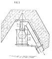
- Fig. 3 die zweite Ausführung des Schwimmerventils in einer der Fig. 2 entsprechenden Darstellung.
- 1 shows a schematic vertical partial section through the lower region of a silo,
- Fig. 2 shows the first embodiment of the float valve in a schematic side view
- Fig. 3 shows the second embodiment of the float valve in a representation corresponding to FIG. 2.
Mittig im Siloraum 1, der von den Wänden 2 umgrenzt ist, ist auf dem Siloboden 3 die hohlkegelige Auslaßkammer 4 angeordnet, in der mittig unten der Auslaß 5 angeordnet ist, an den sich die Auslaßleitung 6, beispielsweise als pneumatische Förderrinne, anschließt. Der Boden der Auslaßkammer ist mit porösen Auflockerungselementen in üblicher Weise ausgerüstet, die von einem Kompressor 7 her über eine Leitung 8 gespeist werden.In the middle of the silo space 1, which is delimited by the
Von dem Oberraum 9 der Auslaßkammer 4 her führt eine Entlüftungsleitung 10 fallend zu der Auslaßleitung 6. Das obere Ende der Entlüftungsleitung 10 ist bei 11. vertikal nach unten gekrümmt zur Bildung der durch den kreisförmigen Rand 12 begrenzten Einlaßöffnung der Entlüftungsleitung. Der Rand 12 ist mit einem gummielastischen Dichtungsring zwecks besserer Abdichtung im Zusammenwirken mit dem Ventilkörper versehen.From the
An das Rohrstück 11 des Entlüftungsrohrs 10 ist koaxial und vertikal darunter der Schwimmerkäfig 13 befestigt, der aus einer Mehrzahl von Käfigstäben 14 und einem daran befestigten Käfigboden 15 gebildet ist. Innerhalb des Käfigs befindet sich als Schwimmer und Ventilkörper die Kugel 16, deren Durchmesser nicht wesentlich geringer ist als der freie Käfigdurchmesser in dessen oberem Bereich, während er nach unten hin weiter wird. Die Kugel 16 ist mit durchgezogenen Linien in der angehobenen Verschlußstellung und mit strichpunktierten Linien in ihrer Ruhestellung gezeigt. Der Käfigboden besteht aus einer oberen porösen Platte 17 und einem an deren Rand dicht angeschlossenen Druckluftzuführungskammer 18, die ihrerseits über die Leitung 19 an das Gebläse 7 angeschlossen ist und vorzugsweise von diesem ständig mit Druckluft beaufschlagt wird.The float cage 13, which is formed from a plurality of
Im Ruhezustand liegt die Kugel 16 auf der Platte 15. Steigt das Gut in der Kammer 4 bis in den Oberraum 9, so dringt es von der Seite her in den Käfig 13 ein und hebt die Kugel 16 an, bis diese die Einlaßöffnung im Zusammenwirken mit deren Rand 12 verschließt. Das Material, daß sich unter ihr im Käfig 13 angesammelt hat, kann nach dem Absinken des Gutspiegels aufgrund der Belüftung durch die poröse Schicht 17 selbst dann wieder abfließen, wenn es zuvor nicht hinreichend fluidisiert gewesen sein sollte.In the idle state, the
Die Ausführung gemäß Fig. 3 unterscheidet sich dadurch von derjenigen gemäß Fig. 2, daß der Ventilkörper 20 doppelkegelig um eine vertikale Achse ausgeführt ist und mit einer Führungsstange 21 in nicht näher dargestellten Führungen innerhalb des Rohrstücks 11 vertikal verschiebbar geführt ist. Dem Käfig kommen in diesem Zusammenhang keine Führungsaufgaben zu, so daß er beliebige Außengestalt haben kann und die Abstände zwischen den Käfigstäben 14 größer als der Durchmesser des Ventilkörpers sein können.The embodiment according to FIG. 3 differs from that according to FIG. 2 in that the
In beiden Ausführungsformen ist die Platte 15 im Durchmesser wesentlich größer als der Ventilkörper 16 bzw. 20, so daß sie der Ventilanordnung einen Schutz vor dem von unten andrängenden Gut in der Weise bietet, daß jedenfalls ein Verschütten der Anordnung durch wenig fluidisiertes Gut nicht möglich ist. Dies ist vielmehr gezwungen, von der Seite her und dadurch beruhigt und gleichzeitig lockerer in die Ventilanordnung einzutreten, so daß sowohl eine größere Wahrscheinlichkeit dafür gegeben ist, daß selbst unter ungünstigen Umständen der Ventilkörper noch hinreichend aufgetrieben wird, als auch die pneumatische Auflockerbarkeit des in den Käfig eingedrungenen Materials durch die aus der porösen Schicht 17 zugeführte Luft zum Zwecke des Ablaufens dieses Guts gewährleistet ist.In both embodiments, the
Claims (1)
Applications Claiming Priority (2)
| Application Number | Priority Date | Filing Date | Title |
|---|---|---|---|
| DE3428715 | 1984-08-03 | ||
| DE3428715A DE3428715A1 (en) | 1984-08-03 | 1984-08-03 | SCHUETTGUTSILO WITH A VENTED EXHAUST CHAMBER |
Publications (2)
| Publication Number | Publication Date |
|---|---|
| EP0170128A2 true EP0170128A2 (en) | 1986-02-05 |
| EP0170128A3 EP0170128A3 (en) | 1987-06-10 |
Family
ID=6242323
Family Applications (1)
| Application Number | Title | Priority Date | Filing Date |
|---|---|---|---|
| EP85108672A Withdrawn EP0170128A3 (en) | 1984-08-03 | 1985-07-11 | Silo for bulk material having an air vent outlet chamber |
Country Status (3)
| Country | Link |
|---|---|
| US (1) | US4630531A (en) |
| EP (1) | EP0170128A3 (en) |
| DE (1) | DE3428715A1 (en) |
Families Citing this family (4)
| Publication number | Priority date | Publication date | Assignee | Title |
|---|---|---|---|---|
| DE3743637A1 (en) * | 1987-12-22 | 1989-07-06 | Krupp Polysius Ag | SILO FOR SCHUETTGUT |
| US6016828A (en) * | 1999-01-04 | 2000-01-25 | Machledt; Charles G. | Vault vent having dual ball water seal |
| US6848465B1 (en) | 2002-04-17 | 2005-02-01 | Robert H. Wager Co., Inc. | Dual-action vent check valve |
| KR20160041468A (en) * | 2014-10-07 | 2016-04-18 | 강은진 | Air conditioning apparatus having waterproof function |
Citations (3)
| Publication number | Priority date | Publication date | Assignee | Title |
|---|---|---|---|---|
| DE2657597A1 (en) * | 1976-12-18 | 1978-06-22 | Peters Ag Claudius | SCHUETTGUTSILO WITH MIXING CHAMBER |
| DE2849014B1 (en) * | 1978-11-11 | 1980-05-14 | Peters Ag Claudius | Bulk material silo with pneumatic emptying and with a vented outlet chamber |
| DE2619993B2 (en) * | 1976-05-06 | 1981-02-12 | Claudius Peters Ag, 2000 Hamburg | Process for removing bulk material from a floor-ventilated silo and removal device for carrying out the process |
Family Cites Families (9)
| Publication number | Priority date | Publication date | Assignee | Title |
|---|---|---|---|---|
| DE7432854U (en) * | 1975-07-10 | Henkel & Cie Gmbh | Aeration and ventilation device for containers | |
| US2757752A (en) * | 1952-07-30 | 1956-08-07 | Jack W Kaufman | Valve assembly for drain conduits |
| US2843146A (en) * | 1955-11-28 | 1958-07-15 | Louis A Kirschner | Drain trap and means for locking same to the waste pipe |
| US2871875A (en) * | 1956-11-19 | 1959-02-03 | Harold E Dale | Valve mounting means |
| US3196774A (en) * | 1962-06-27 | 1965-07-27 | Behlen Mfg Company Inc | Method of and means for circulating air within closed buildings |
| CH492621A (en) * | 1969-12-11 | 1970-06-30 | Alusuisse | Emptying device on silos with a flat bottom |
| US4088149A (en) * | 1976-05-20 | 1978-05-09 | Logsdon Duane D | Check valve structure for use in drains |
| US4129069A (en) * | 1977-08-17 | 1978-12-12 | Thompson Andy L | Breather bag apparatus |
| DE7935648U1 (en) * | 1979-12-18 | 1980-03-20 | Krupp Polysius Ag, 4720 Beckum | SILO FOR PNEUMATICALLY MIXING AND HOMOGENIZING FINE PRODUCTS |
-
1984
- 1984-08-03 DE DE3428715A patent/DE3428715A1/en not_active Withdrawn
-
1985
- 1985-07-11 EP EP85108672A patent/EP0170128A3/en not_active Withdrawn
- 1985-07-30 US US06/760,467 patent/US4630531A/en not_active Expired - Fee Related
Patent Citations (3)
| Publication number | Priority date | Publication date | Assignee | Title |
|---|---|---|---|---|
| DE2619993B2 (en) * | 1976-05-06 | 1981-02-12 | Claudius Peters Ag, 2000 Hamburg | Process for removing bulk material from a floor-ventilated silo and removal device for carrying out the process |
| DE2657597A1 (en) * | 1976-12-18 | 1978-06-22 | Peters Ag Claudius | SCHUETTGUTSILO WITH MIXING CHAMBER |
| DE2849014B1 (en) * | 1978-11-11 | 1980-05-14 | Peters Ag Claudius | Bulk material silo with pneumatic emptying and with a vented outlet chamber |
Also Published As
| Publication number | Publication date |
|---|---|
| EP0170128A3 (en) | 1987-06-10 |
| US4630531A (en) | 1986-12-23 |
| DE3428715A1 (en) | 1986-02-13 |
Similar Documents
| Publication | Publication Date | Title |
|---|---|---|
| DE2205716A1 (en) | Feeding device for bulk goods | |
| WO2001037980A2 (en) | Device for coating particles | |
| CH671211A5 (en) | ||
| DE4130056C2 (en) | Device for watering poultry and small animals | |
| DE3245943C2 (en) | Outlet valve for low-foam delivery of loose fresh milk in measured quantities to the consumer | |
| EP0170128A2 (en) | Silo for bulk material having an air vent outlet chamber | |
| EP0001422B1 (en) | Apparatus for pneumatically discharging fine material from a container and method of operation therefor | |
| DE3022346C2 (en) | Mixing silo for bulk goods | |
| DE2657597C2 (en) | Bulk material silo with homogenization chamber | |
| DE1129892B (en) | Emptying device for flat-bottomed silos for dusty or fine-grained goods | |
| DE2914016C2 (en) | ||
| DE2513479A1 (en) | METHOD FOR NON-MACHINE DELIVERY OF A COLLECTED LIQUID AND EQUIPMENT FOR CARRYING OUT THE PROCEDURE | |
| WO1984004964A1 (en) | Device for dosing fluids | |
| DE2530270A1 (en) | DEVICE FOR GIVING CONTACT BETWEEN A LIQUID AND A GAS | |
| DE7531503U (en) | EMPTYING DEVICE ON FLAT-HED BULK BANKS | |
| DE4038901C2 (en) | ||
| DE1268062B (en) | Device for emptying a silo cell for bulk goods that can be pneumatically displaced into a flowable state | |
| DE2154006C3 (en) | Mixing silo for powdery material | |
| DE3024327C2 (en) | Funnel-shaped discharge for bulk material containers | |
| DE482706C (en) | Ventilation and emptying device for grain silos | |
| DE4328071A1 (en) | Device for removing heavy flowing bulk goods from a silo | |
| DE7132212U (en) | Ventable container bottom for the pneumatic discharge of dry fine material from a container | |
| DE2849014B1 (en) | Bulk material silo with pneumatic emptying and with a vented outlet chamber | |
| DE3523256A1 (en) | Apparatus for pneumatically conveying fine material | |
| DE2258185C3 (en) | Stationary device for the continuous distribution of pumpable feed mixtures to animals |
Legal Events
| Date | Code | Title | Description |
|---|---|---|---|
| PUAI | Public reference made under article 153(3) epc to a published international application that has entered the european phase |
Free format text: ORIGINAL CODE: 0009012 |
|
| AK | Designated contracting states |
Designated state(s): DE FR GB IT |
|
| PUAL | Search report despatched |
Free format text: ORIGINAL CODE: 0009013 |
|
| AK | Designated contracting states |
Kind code of ref document: A3 Designated state(s): DE FR GB IT |
|
| RHK1 | Main classification (correction) |
Ipc: B65D 88/72 |
|
| 17P | Request for examination filed |
Effective date: 19870730 |
|
| 17Q | First examination report despatched |
Effective date: 19880505 |
|
| RAP1 | Party data changed (applicant data changed or rights of an application transferred) |
Owner name: CLAUDIUS PETERS AKTIENGESELLSCHAFT |
|
| STAA | Information on the status of an ep patent application or granted ep patent |
Free format text: STATUS: THE APPLICATION IS DEEMED TO BE WITHDRAWN |
|
| 18D | Application deemed to be withdrawn |
Effective date: 19881025 |
|
| RIN1 | Information on inventor provided before grant (corrected) |
Inventor name: KRAUSS, WERNER |