EP0169476B1 - Vorrichtung zur Durchführung eines Rollenwechsels - Google Patents
Vorrichtung zur Durchführung eines Rollenwechsels Download PDFInfo
- Publication number
- EP0169476B1 EP0169476B1 EP85108866A EP85108866A EP0169476B1 EP 0169476 B1 EP0169476 B1 EP 0169476B1 EP 85108866 A EP85108866 A EP 85108866A EP 85108866 A EP85108866 A EP 85108866A EP 0169476 B1 EP0169476 B1 EP 0169476B1
- Authority
- EP
- European Patent Office
- Prior art keywords
- web
- regulating circuit
- regulator
- roll
- speed
- Prior art date
- Legal status (The legal status is an assumption and is not a legal conclusion. Google has not performed a legal analysis and makes no representation as to the accuracy of the status listed.)
- Expired - Lifetime
Links
- 230000008859 change Effects 0.000 title claims description 25
- 230000001105 regulatory effect Effects 0.000 claims description 21
- 238000012545 processing Methods 0.000 claims description 9
- 230000001276 controlling effect Effects 0.000 claims description 2
- 230000001133 acceleration Effects 0.000 description 4
- 238000011144 upstream manufacturing Methods 0.000 description 4
- 230000006870 function Effects 0.000 description 3
- 238000012544 monitoring process Methods 0.000 description 3
- 230000004044 response Effects 0.000 description 3
- 230000000694 effects Effects 0.000 description 2
- 238000000034 method Methods 0.000 description 2
- 230000008569 process Effects 0.000 description 2
- 238000004804 winding Methods 0.000 description 2
- 239000002390 adhesive tape Substances 0.000 description 1
- 230000003321 amplification Effects 0.000 description 1
- 230000008901 benefit Effects 0.000 description 1
- 230000005540 biological transmission Effects 0.000 description 1
- 238000001514 detection method Methods 0.000 description 1
- 238000011161 development Methods 0.000 description 1
- 230000018109 developmental process Effects 0.000 description 1
- 238000004519 manufacturing process Methods 0.000 description 1
- 238000003199 nucleic acid amplification method Methods 0.000 description 1
- 230000002093 peripheral effect Effects 0.000 description 1
- 230000035945 sensitivity Effects 0.000 description 1
- 230000035939 shock Effects 0.000 description 1
- 238000013519 translation Methods 0.000 description 1
Images
Classifications
-
- B—PERFORMING OPERATIONS; TRANSPORTING
- B65—CONVEYING; PACKING; STORING; HANDLING THIN OR FILAMENTARY MATERIAL
- B65H—HANDLING THIN OR FILAMENTARY MATERIAL, e.g. SHEETS, WEBS, CABLES
- B65H19/00—Changing the web roll
- B65H19/10—Changing the web roll in unwinding mechanisms or in connection with unwinding operations
- B65H19/14—Accumulating surplus web for advancing to machine while changing the web roll
-
- B—PERFORMING OPERATIONS; TRANSPORTING
- B65—CONVEYING; PACKING; STORING; HANDLING THIN OR FILAMENTARY MATERIAL
- B65H—HANDLING THIN OR FILAMENTARY MATERIAL, e.g. SHEETS, WEBS, CABLES
- B65H2408/00—Specific machines
- B65H2408/20—Specific machines for handling web(s)
- B65H2408/21—Accumulators
- B65H2408/217—Accumulators of rollers type, e.g. with at least one fixed and one movable roller
- B65H2408/2171—Accumulators of rollers type, e.g. with at least one fixed and one movable roller the position of the movable roller(s), i.e. the web loop, being positively actuated
-
- B—PERFORMING OPERATIONS; TRANSPORTING
- B65—CONVEYING; PACKING; STORING; HANDLING THIN OR FILAMENTARY MATERIAL
- B65H—HANDLING THIN OR FILAMENTARY MATERIAL, e.g. SHEETS, WEBS, CABLES
- B65H2553/00—Sensing or detecting means
- B65H2553/51—Encoders, e.g. linear
Definitions
- the invention relates to a device according to the preamble of claim 1.
- a device of this type is known from DE-U 7 501 986.
- a spindle which interacts with a nut provided on the slide is driven during the change of roles via a rigid shaft by an output of a branching gear, for example in the form of a planetary gear, the input of which via another rigid shaft is located at the output of an actuating gear, which is by means of the the drive shaft assigned to the processing machine is driven and its translation should be changeable by means of a so-called three-point controller as a function of a change in the web tension.
- Another output of the branching transmission which can be activated as an alternative to the slide-side output, is connected to a pulling device which is arranged upstream of the memory and which stands still when the roll change is carried out.
- JP-A-54 116519 does indeed result in a web store with a drive motor. In normal processing operations, this is regulated depending on the web speed difference between the memory input and the memory output in order to keep the web tension constant.
- An arrangement of this type is not suitable for controlling the drive motor assigned to the web store when performing a roll change with the roll stationary.
- DE-A 2 313 857 shows a device for carrying out a roll change when the roll is at a standstill with a displaceable carriage which is driven by means of a controllable drive device during the emptying of the memory.
- a controllable drive device during the emptying of the memory.
- DE-A 1774780 contains a control device for a winding machine, in which a web tension control circuit acting on the winding drive and a speed control circuit are provided.
- these two control loops are not superordinate or subordinate to one another, but can alternatively be connected to the controller of an energy supply control loop. Only the speed control loop should be active for the role change.
- the technical progress that can be achieved with these measures can be seen in particular in avoiding the disadvantages of the known arrangements.
- the use of an individual drive assigned to the carriage, which is independent of the drive of the processing machine and of the roller drive, advantageously enables cascade control in which, due to its multi-stage nature, only very small changes in the controlled variable result and therefore extremely smooth running of the web.
- the higher-level control loops advantageously have a corrective effect on the controller of the respective downstream control loop with their controller output, the fastest control loop, which monitors fluctuations in the energy flow, being the most subordinate control loop and the slowest, the web tension monitoring control loop being the most high-level control loop, which on the one hand ensures extremely short dead times and on the other hand a high level of sensitivity.
- the measures of claim 2 ensure the same operating conditions in each quadrant.
- the measures of claim 3 enable a simple and exact detection of the web tension on the basis of a change in position of the dancer roller, which at the same time represents a flexible link within the web guide.
- the measures of claim 4 result in particularly short response times. Another advantage can be seen in the fact that the tachogenerators used emit analog electrical signals to the speed recorded.
- the measures of claim 5 ensure that the same in and outside the role change be actual web tension sensor and target value transmitter can be used.
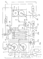
- FIG. 1 The only figure in the drawing shows a schematic illustration of a reel changer according to the invention arranged upstream of a printing press and the control system associated therewith.
- the roll changer 3 arranged upstream of the printing press 1 contains a roll holder 6 with stacking devices 7 for the rolls 4, 5 arranged one above the other and with a web connecting device 8 and with drive devices 9 assigned to the rolls 4 and 5.
- the roll changer 3 also contains a web store arranged downstream of the roll holder 6 10, which is provided for receiving a web supply with stationary arranged on the bottom, received on a movable up and down carriage 12, movable relative to the stationary arranged deflection rollers 11.
- the web 2 is looped around the deflection rollers 11 and 13, respectively.
- the carriage 12 is received here on chain wheels 14, here endless lifting chains 15, which can be driven by means of an associated drive unit 16 which is firmly coupled to a pair of chain wheels.
- the drawing is based on an operating state in which the running web 2 is removed from the upper roll 4 and the lower web 5 is held in a waiting position.
- the diameter of the roll feeding the running web 2 can be monitored by means of a sensor 17.
- the respective roll diameter is determined by means of a computer 17, which compares the pulses emitted when the running roll rotates, picked up by means of a pulse generator 17a, with pulses given by each pulse of the cylinders of the printing press 1 processing the web 2 and recorded by means of a pulse generator 17b and from this the current roll diameter is calculated.
- the roll change is initiated when a preselected minimum diameter is reached. In the present case, this should take place when the roll is at a standstill.
- the running roller 4 is braked to a standstill.
- the run-off path 2a running therefrom is then cut.
- the rear web end produced in this way is then glued to the beginning of the connecting web 2b contained on a new roll, here the lower roll 5.
- the memory 10 which contains a certain web supply, is emptied. After the role change has been carried out, the memory 10 is refilled.
- the carriage 12, which is forcibly drivable with the aid of the drive unit 16, is moved downwards to empty the store 10 and vice versa.
- the carriage 12 is forcibly driven during the emptying of the memory with the aid of the associated drive unit 16 in such a way that as much web is always released as is required to keep the web tension constant within narrow limits.
- the drive unit 16 assigned to the carriage 12 is designed here as a direct current machine which is connected to a power supply network via a supply line 18.
- a DC machine is a so-called four-quadrant machine, which enables a stepless change from + to - and vice versa, both in terms of speed and torque, which is a prerequisite for avoiding voltage peaks at the reversal points.
- An adjustable resistor can be provided in the supply line 18 to influence the voltage.
- a four-quadrant thyristor current converter 19 is provided for this. This is a compact element with high efficiency and low losses.
- the four-quadrant thyristor current converter 19 is adjusted by means of a control device so that the memory 10 always releases the web length required to keep the web tension constant.
- a first control circuit 20 is provided with a controller 23, the output of which is connected to the thyristor current converter 19.
- the controller 23 has two inputs, one of which is connected to an actual value transmitter 22 and the other is connected to a signal line 21 assigned to a setpoint.
- a current or voltage measuring device arranged in the supply line 18 is used to form the actual value sensor 22.
- the signal line 21 forms the output of a superimposed control circuit 27, by means of which speed fluctuations in the area of the printing press 1 and thus fluctuations in the web feed speed are detected.
- the control circuit 27 which is cascade-like superimposed on the control circuit used to switch off current or voltage fluctuations in the supply network, comprises a controller 24, a Setpoint generator 25 and an actual value transducer 26.
- the setpoint generator 25 of this cascade control circuit 27 is designed here as a tachometer generator that can be driven at the drive speed of the printing press 1.
- the setpoint generator 25, which is designed as a tachometer generator can simply be firmly coupled to the machine longitudinal shaft.
- the actual value transmitter 26 is designed as a tachometer generator which is driven with the drive speed of the drive unit 16 assigned to the carriage 12. Instead of a tachometer generator, a digital-to-analog converter could also be provided.
- the controller 24 of the speed control circuit 27 has three inputs. At the third input there is the output of a controller 28 of a further, cascaded superordinate control circuit 29, by means of which web tension fluctuations are directly detected.
- the actual value sensor used for this can be a force sensor that measures the force acting on the bearings of a roller wrapped in the web 2.
- the actual value pickup contains a dancer roller 30 and a transducer 31 arranged downstream of it.
- the dancer roller 30 changes its position depending on the web tension. This change in position is detected with the aid of converter 31 and is given to the assigned controller 28 in the form of an electrical signal as the actual value.
- a manually adjustable potentiometer which is set to a value corresponding to the desired position of the dancer roller 30, can be used as the setpoint generator 32 of the web tension control circuit 29.
- the three-stage cascade control ensures that the higher-level control loops 27 and 29, with their controller outputs, have a corrective effect on the controller of the respective downstream control loop, the fastest control loop 20 monitoring the network fluctuations being the most subordinate and the slowest, changing the position of the
- the control circuit 29 monitoring the dancer roller 30 is the most superordinate control circuit, which is a very quickly responsive and yet very sensitive, ie result in small control variable changes.
- the memory 10 emptied during these phases is refilled, while the new roll is processed until a minimum diameter is reached.
- the drive device 9 respectively assigned to the running reel is driven after the desired peripheral speed has been reached at a speed regulated in the same manner as before for the drive unit 16.
- a basic control circuit 20a is provided to compensate for current and voltage fluctuations in the energy supply network, the structure of which corresponds to the control circuit 20 and which is therefore only indicated by a dash-dotted outline.
- This control circuit 20a acts on the energy supply assigned to the drive devices 9 and illustrated by the line 33.
- a further control circuit 27a, which operates as a function of a change in the web speed, and this control circuit 29a, which operates as a function of a change in the web tension, are cascaded over this basic control circuit 20a.
- a controller 24a is provided with its output at the third input of the controller of the basic control circuit 20a, which is connected in parallel to the controller 24 of the web speed control circuit 27 to the tachometer generator forming the setpoint generator 25 and driven by the longitudinal shaft of the printing press 1, and the like assigned with the speed of the drive devices 9 which can be driven to the respectively running roller 4 or 5 and are here also designed as tachometer generators 34.
- a logic element 39 is arranged upstream of the actual value input of the controller 24a, into which the signals emitted by the actual value sensors 34 and the signals emitted by the computer 17 are fed.
- a controller 28a is provided with its output at the third input of the controller 24a of the subordinate basic control circuit 27a, which is connected in parallel to the controller 28 of the web tension control circuit 29 to the setpoint generator 32 and, alternatively to the controller 28, to the through the dancer roller 30 and the converter 31 can be placed actual web tension sensor.
- the actual value signal line 35 is branched and provided with a switch 36, by means of which the actual value generator formed by the dancer roller 30 and the converter 31 in the normal state with the controller 28a of the control circuit 29a assigned to the roller drive devices 9 and while the role change is being carried out until it is reached the normal running speed of the running roller can be connected to the controller 28 of the control circuit 29 assigned to the slide drive unit 16. This operating position is indicated in the drawing with solid lines.
- the switching process which can be carried out by means of the switch 36 takes place after the end of the roll change and the acceleration of the new roll, that is to say after the storage 10 has been emptied guided this superordinate speed control loop 27.
- the third input of the controller 24 of the speed control circuit 27 is connected to an adjustable potentiometer 37 which specifies the desired end position of the slide 12 and thus the desired path reserve in the memory 10.
- a switch 38 is provided in the signal line assigned to the third input of the controller 24, by means of which the controller 24 can alternatively be connected to the potentiometer 37 or the controller 28 of the higher-level control circuit 29.
- the drive unit 16 switches off automatically.
- the switches 36 and 38 can be operated individually or preferably together.
Landscapes
- Controlling Rewinding, Feeding, Winding, Or Abnormalities Of Webs (AREA)
Applications Claiming Priority (2)
| Application Number | Priority Date | Filing Date | Title |
|---|---|---|---|
| DE19843426976 DE3426976A1 (de) | 1984-07-21 | 1984-07-21 | Vorrichtung zur durchfuehrung eines rollenwechsels |
| DE3426976 | 1984-07-21 |
Publications (3)
| Publication Number | Publication Date |
|---|---|
| EP0169476A2 EP0169476A2 (de) | 1986-01-29 |
| EP0169476A3 EP0169476A3 (en) | 1988-02-17 |
| EP0169476B1 true EP0169476B1 (de) | 1990-01-31 |
Family
ID=6241250
Family Applications (1)
| Application Number | Title | Priority Date | Filing Date |
|---|---|---|---|
| EP85108866A Expired - Lifetime EP0169476B1 (de) | 1984-07-21 | 1985-07-16 | Vorrichtung zur Durchführung eines Rollenwechsels |
Country Status (2)
| Country | Link |
|---|---|
| EP (1) | EP0169476B1 (enExample) |
| DE (2) | DE3426976A1 (enExample) |
Cited By (1)
| Publication number | Priority date | Publication date | Assignee | Title |
|---|---|---|---|---|
| CN105836510A (zh) * | 2011-02-24 | 2016-08-10 | 株式会社尼康 | 片基板的搬送装置及处理装置 |
Families Citing this family (11)
| Publication number | Priority date | Publication date | Assignee | Title |
|---|---|---|---|---|
| US4762289A (en) * | 1986-02-28 | 1988-08-09 | Harland Machine Systems Limited | Continuous supply of elongate material |
| DD252360A1 (de) * | 1986-08-27 | 1987-12-16 | Polygraph Leipzig | Vorrichtung zum regeln des abrollens in abwickeleinrichtungen |
| JPH0678139B2 (ja) * | 1990-04-13 | 1994-10-05 | エス・ケイエンジニアリング株式会社 | ウェブ自動継ぎ装置 |
| DE19838545A1 (de) | 1998-08-25 | 2000-03-02 | Focke & Co | Verfahren und Vorrichtung zum Erkennen von Druckmarken |
| EP1013585A1 (en) * | 1998-12-24 | 2000-06-28 | Fameccanica.Data S.p.A. | Device for supplying web material |
| DE19925108A1 (de) * | 1999-06-01 | 2000-12-07 | Honigmann Ind Elektronik Gmbh | Vorrichtung zum Abzug von Bändern |
| DE102004049932B4 (de) * | 2004-10-13 | 2006-11-16 | WINKLER + DüNNEBIER AG | Vorrichtung zum Verbinden des Endstückes einer ersten Materialbahn mit dem Anfangsstück einer zweiten Materialbahn |
| DE102005008223A1 (de) * | 2005-02-22 | 2006-08-31 | Man Roland Druckmaschinen Ag | Rollenwechsler einer Rollendruckmaschine sowie Verfahren zur Regelung eines Rollenwechslers |
| CN101070130B (zh) * | 2007-06-19 | 2010-05-19 | 国营红阳机械厂 | 具张力控制的卷材动态存贮设备 |
| DE102008022702B4 (de) | 2008-05-07 | 2011-03-24 | Windmöller & Hölscher Kg | Verfahren und eine Vorrichtung zum Abwickeln und zum Speichern von bahnförmigem Material |
| DE102010001535A1 (de) * | 2010-02-03 | 2011-08-04 | manroland AG, 63075 | Verfahren zur Regelung eines Rollenwechslers sowie Rollenwechsler |
Family Cites Families (5)
| Publication number | Priority date | Publication date | Assignee | Title |
|---|---|---|---|---|
| US3519903A (en) * | 1967-09-05 | 1970-07-07 | Westinghouse Electric Corp | System for controlling a strip material roll as a function of speed or tension of traveling strip material |
| US3822838A (en) * | 1972-03-20 | 1974-07-09 | Butler Automatic Inc | Web handling apparatus |
| DE7501986U (de) * | 1975-01-24 | 1975-09-04 | Maschinenfabrik Goebel Gmbh | Einrichtung zum Bewegen eines Walzenträgers. |
| US4151594A (en) * | 1976-02-26 | 1979-04-24 | Bobst-Champlain, Inc. | Web tension control for high-speed web handling equipment |
| JPS5931244A (ja) * | 1982-08-09 | 1984-02-20 | Dainippon Printing Co Ltd | 給紙装置の紙継ぎ方法 |
-
1984
- 1984-07-21 DE DE19843426976 patent/DE3426976A1/de active Granted
-
1985
- 1985-07-16 EP EP85108866A patent/EP0169476B1/de not_active Expired - Lifetime
- 1985-07-16 DE DE8585108866T patent/DE3575709D1/de not_active Expired - Fee Related
Cited By (2)
| Publication number | Priority date | Publication date | Assignee | Title |
|---|---|---|---|---|
| CN105836510A (zh) * | 2011-02-24 | 2016-08-10 | 株式会社尼康 | 片基板的搬送装置及处理装置 |
| CN105836510B (zh) * | 2011-02-24 | 2017-11-28 | 株式会社尼康 | 片基板的搬送装置及处理装置 |
Also Published As
| Publication number | Publication date |
|---|---|
| DE3426976A1 (de) | 1986-01-30 |
| EP0169476A2 (de) | 1986-01-29 |
| DE3426976C2 (enExample) | 1988-12-15 |
| DE3575709D1 (de) | 1990-03-08 |
| EP0169476A3 (en) | 1988-02-17 |
Similar Documents
| Publication | Publication Date | Title |
|---|---|---|
| DE2954509C2 (enExample) | ||
| EP0169476B1 (de) | Vorrichtung zur Durchführung eines Rollenwechsels | |
| DE9216261U1 (de) | Vorrichtung zum Aufwickeln einer Bahn | |
| DE2313857A1 (de) | Zufuehreinrichtung fuer bahnmaterial | |
| EP0298267B1 (de) | Vorrichtung zum Auf- und Abwickeln von in Form eines Schuppenstromes mittels eines Förderers zu- bzw weggeführten Druckereiprodukten | |
| DE2625349C2 (de) | Vorrichtung zum funkenerosiven oder elektrochemischen Bearbeiten von Werkstücken | |
| EP2386511A1 (de) | Regelung der Bahnspannung einer Warenbahn | |
| DE10081432B4 (de) | Vorrichtung zum Abzug von Bändern | |
| EP3239369A1 (de) | Ballenöffner | |
| DE3135696C2 (de) | Verfahren und Vorrichtung zum Drucken veränderlicher Formate | |
| DE2732644C2 (de) | Regelanordnung für einen Rollenträger | |
| DE2256882B2 (de) | Regelvorrichtung vor dem einlauf in eine die papierbahn ziehende bearbeitungsmaschine | |
| DE2631573C3 (de) | Verfahren und Vorrichtung zum Schären von Fäden | |
| DE1560015B1 (de) | Stoffablegemaschine | |
| DE2741083C2 (de) | Friktionswickelwellenantrieb | |
| DE3827509A1 (de) | Antrieb insbesondere fuer den schweissdrahtvorschub an schweisseinrichtungen | |
| DE2650287C2 (de) | Verzugseinrichtung für Faserbänder | |
| DE2230628C3 (de) | Vorrichtung zum Steuern des Antriebs der Verlegevorrichtung von Spulmaschinen, insbesondere bei Drahtziehmaschinen | |
| DE1535152A1 (de) | Verfahren zum Umbaeumen und Aufwickeln von Fadenscharen und Materialbahnen | |
| DE19704702B4 (de) | Elimination von Lose-Effekten in Druckmaschinen | |
| DE4312534A1 (de) | Vorrichtung zur Regelung der Bahnspannungsregelung einer Materialbahn, insbesondere einer Papierbahn | |
| DE1124407B (de) | Spulmaschine zur Erzeugung von Spulen mit ueber der Spulreise vorbestimmter Fadenspannung | |
| DE1774780A1 (de) | Einrichtung zum Regeln von Wicklerantrieben | |
| DE102013224324A1 (de) | Verfahren zum Betrieb einer Bahnbearbeitungsmaschine mit fliegendem Rollenwechsel | |
| DE1236637B (de) | Einrichtung zum Antrieb eines Schlingenhebers fuer Walzenstrassen |
Legal Events
| Date | Code | Title | Description |
|---|---|---|---|
| PUAI | Public reference made under article 153(3) epc to a published international application that has entered the european phase |
Free format text: ORIGINAL CODE: 0009012 |
|
| AK | Designated contracting states |
Designated state(s): CH DE FR GB LI NL SE |
|
| PUAL | Search report despatched |
Free format text: ORIGINAL CODE: 0009013 |
|
| AK | Designated contracting states |
Kind code of ref document: A3 Designated state(s): CH DE FR GB LI NL SE |
|
| 17P | Request for examination filed |
Effective date: 19880421 |
|
| 17Q | First examination report despatched |
Effective date: 19880708 |
|
| GRAA | (expected) grant |
Free format text: ORIGINAL CODE: 0009210 |
|
| AK | Designated contracting states |
Kind code of ref document: B1 Designated state(s): CH DE FR GB LI NL SE |
|
| REF | Corresponds to: |
Ref document number: 3575709 Country of ref document: DE Date of ref document: 19900308 |
|
| ET | Fr: translation filed | ||
| GBT | Gb: translation of ep patent filed (gb section 77(6)(a)/1977) | ||
| PLBE | No opposition filed within time limit |
Free format text: ORIGINAL CODE: 0009261 |
|
| STAA | Information on the status of an ep patent application or granted ep patent |
Free format text: STATUS: NO OPPOSITION FILED WITHIN TIME LIMIT |
|
| 26N | No opposition filed | ||
| PGFP | Annual fee paid to national office [announced via postgrant information from national office to epo] |
Ref country code: GB Payment date: 19920515 Year of fee payment: 8 |
|
| PGFP | Annual fee paid to national office [announced via postgrant information from national office to epo] |
Ref country code: FR Payment date: 19920625 Year of fee payment: 8 |
|
| PGFP | Annual fee paid to national office [announced via postgrant information from national office to epo] |
Ref country code: CH Payment date: 19920630 Year of fee payment: 8 |
|
| PGFP | Annual fee paid to national office [announced via postgrant information from national office to epo] |
Ref country code: SE Payment date: 19920703 Year of fee payment: 8 |
|
| PGFP | Annual fee paid to national office [announced via postgrant information from national office to epo] |
Ref country code: DE Payment date: 19920709 Year of fee payment: 8 |
|
| PGFP | Annual fee paid to national office [announced via postgrant information from national office to epo] |
Ref country code: NL Payment date: 19920731 Year of fee payment: 8 |
|
| PG25 | Lapsed in a contracting state [announced via postgrant information from national office to epo] |
Ref country code: GB Effective date: 19930716 |
|
| PG25 | Lapsed in a contracting state [announced via postgrant information from national office to epo] |
Ref country code: SE Effective date: 19930717 |
|
| PG25 | Lapsed in a contracting state [announced via postgrant information from national office to epo] |
Ref country code: LI Effective date: 19930731 Ref country code: CH Effective date: 19930731 |
|
| PG25 | Lapsed in a contracting state [announced via postgrant information from national office to epo] |
Ref country code: NL Effective date: 19940201 |
|
| GBPC | Gb: european patent ceased through non-payment of renewal fee |
Effective date: 19930716 |
|
| NLV4 | Nl: lapsed or anulled due to non-payment of the annual fee | ||
| PG25 | Lapsed in a contracting state [announced via postgrant information from national office to epo] |
Ref country code: FR Effective date: 19940331 |
|
| REG | Reference to a national code |
Ref country code: CH Ref legal event code: PL |
|
| PG25 | Lapsed in a contracting state [announced via postgrant information from national office to epo] |
Ref country code: DE Effective date: 19940401 |
|
| REG | Reference to a national code |
Ref country code: FR Ref legal event code: ST |
|
| EUG | Se: european patent has lapsed |
Ref document number: 85108866.6 Effective date: 19940210 |