EP0164489A2 - Dispositif pour le broyage de matériau granuleux et/ou fibreux - Google Patents
Dispositif pour le broyage de matériau granuleux et/ou fibreux Download PDFInfo
- Publication number
- EP0164489A2 EP0164489A2 EP85101014A EP85101014A EP0164489A2 EP 0164489 A2 EP0164489 A2 EP 0164489A2 EP 85101014 A EP85101014 A EP 85101014A EP 85101014 A EP85101014 A EP 85101014A EP 0164489 A2 EP0164489 A2 EP 0164489A2
- Authority
- EP
- European Patent Office
- Prior art keywords
- rotor
- strips
- tools
- saw
- disks
- Prior art date
- Legal status (The legal status is an assumption and is not a legal conclusion. Google has not performed a legal analysis and makes no representation as to the accuracy of the status listed.)
- Granted
Links
Images


Classifications
-
- A—HUMAN NECESSITIES
- A01—AGRICULTURE; FORESTRY; ANIMAL HUSBANDRY; HUNTING; TRAPPING; FISHING
- A01F—PROCESSING OF HARVESTED PRODUCE; HAY OR STRAW PRESSES; DEVICES FOR STORING AGRICULTURAL OR HORTICULTURAL PRODUCE
- A01F29/00—Cutting apparatus specially adapted for cutting hay, straw or the like
- A01F29/09—Details
- A01F29/095—Mounting or adjusting of knives
-
- A—HUMAN NECESSITIES
- A01—AGRICULTURE; FORESTRY; ANIMAL HUSBANDRY; HUNTING; TRAPPING; FISHING
- A01F—PROCESSING OF HARVESTED PRODUCE; HAY OR STRAW PRESSES; DEVICES FOR STORING AGRICULTURAL OR HORTICULTURAL PRODUCE
- A01F29/00—Cutting apparatus specially adapted for cutting hay, straw or the like
- A01F29/005—Cutting apparatus specially adapted for cutting hay, straw or the like for disintegrating and cutting up bales of hay, straw or fodder
-
- A—HUMAN NECESSITIES
- A01—AGRICULTURE; FORESTRY; ANIMAL HUSBANDRY; HUNTING; TRAPPING; FISHING
- A01F—PROCESSING OF HARVESTED PRODUCE; HAY OR STRAW PRESSES; DEVICES FOR STORING AGRICULTURAL OR HORTICULTURAL PRODUCE
- A01F29/00—Cutting apparatus specially adapted for cutting hay, straw or the like
- A01F29/02—Cutting apparatus specially adapted for cutting hay, straw or the like having rotating knives with their cutting edges in a plane perpendicular to their rotational axis
- A01F29/04—Cutting apparatus specially adapted for cutting hay, straw or the like having rotating knives with their cutting edges in a plane perpendicular to their rotational axis with feeding direction transverse to axis
-
- A—HUMAN NECESSITIES
- A01—AGRICULTURE; FORESTRY; ANIMAL HUSBANDRY; HUNTING; TRAPPING; FISHING
- A01F—PROCESSING OF HARVESTED PRODUCE; HAY OR STRAW PRESSES; DEVICES FOR STORING AGRICULTURAL OR HORTICULTURAL PRODUCE
- A01F29/00—Cutting apparatus specially adapted for cutting hay, straw or the like
- A01F29/06—Cutting apparatus specially adapted for cutting hay, straw or the like having rotating knives with their cutting edges on a cylinder surface, e.g. of the helical-type
-
- B—PERFORMING OPERATIONS; TRANSPORTING
- B02—CRUSHING, PULVERISING, OR DISINTEGRATING; PREPARATORY TREATMENT OF GRAIN FOR MILLING
- B02C—CRUSHING, PULVERISING, OR DISINTEGRATING IN GENERAL; MILLING GRAIN
- B02C13/00—Disintegrating by mills having rotary beater elements ; Hammer mills
- B02C13/02—Disintegrating by mills having rotary beater elements ; Hammer mills with horizontal rotor shaft
- B02C13/04—Disintegrating by mills having rotary beater elements ; Hammer mills with horizontal rotor shaft with beaters hinged to the rotor; Hammer mills
-
- B—PERFORMING OPERATIONS; TRANSPORTING
- B02—CRUSHING, PULVERISING, OR DISINTEGRATING; PREPARATORY TREATMENT OF GRAIN FOR MILLING
- B02C—CRUSHING, PULVERISING, OR DISINTEGRATING IN GENERAL; MILLING GRAIN
- B02C13/00—Disintegrating by mills having rotary beater elements ; Hammer mills
- B02C13/26—Details
- B02C13/282—Shape or inner surface of mill-housings
-
- B—PERFORMING OPERATIONS; TRANSPORTING
- B02—CRUSHING, PULVERISING, OR DISINTEGRATING; PREPARATORY TREATMENT OF GRAIN FOR MILLING
- B02C—CRUSHING, PULVERISING, OR DISINTEGRATING IN GENERAL; MILLING GRAIN
- B02C18/00—Disintegrating by knives or other cutting or tearing members which chop material into fragments
- B02C18/06—Disintegrating by knives or other cutting or tearing members which chop material into fragments with rotating knives
- B02C18/14—Disintegrating by knives or other cutting or tearing members which chop material into fragments with rotating knives within horizontal containers
-
- B—PERFORMING OPERATIONS; TRANSPORTING
- B02—CRUSHING, PULVERISING, OR DISINTEGRATING; PREPARATORY TREATMENT OF GRAIN FOR MILLING
- B02C—CRUSHING, PULVERISING, OR DISINTEGRATING IN GENERAL; MILLING GRAIN
- B02C18/00—Disintegrating by knives or other cutting or tearing members which chop material into fragments
- B02C18/06—Disintegrating by knives or other cutting or tearing members which chop material into fragments with rotating knives
- B02C18/16—Details
- B02C18/18—Knives; Mountings thereof
- B02C18/186—Axially elongated knives
-
- B—PERFORMING OPERATIONS; TRANSPORTING
- B02—CRUSHING, PULVERISING, OR DISINTEGRATING; PREPARATORY TREATMENT OF GRAIN FOR MILLING
- B02C—CRUSHING, PULVERISING, OR DISINTEGRATING IN GENERAL; MILLING GRAIN
- B02C18/00—Disintegrating by knives or other cutting or tearing members which chop material into fragments
- B02C18/06—Disintegrating by knives or other cutting or tearing members which chop material into fragments with rotating knives
- B02C18/16—Details
- B02C18/22—Feed or discharge means
- B02C18/2216—Discharge means
-
- B—PERFORMING OPERATIONS; TRANSPORTING
- B27—WORKING OR PRESERVING WOOD OR SIMILAR MATERIAL; NAILING OR STAPLING MACHINES IN GENERAL
- B27L—REMOVING BARK OR VESTIGES OF BRANCHES; SPLITTING WOOD; MANUFACTURE OF VENEER, WOODEN STICKS, WOOD SHAVINGS, WOOD FIBRES OR WOOD POWDER
- B27L11/00—Manufacture of wood shavings, chips, powder, or the like; Tools therefor
- B27L11/02—Manufacture of wood shavings, chips, powder, or the like; Tools therefor of wood shavings or the like
-
- B—PERFORMING OPERATIONS; TRANSPORTING
- B02—CRUSHING, PULVERISING, OR DISINTEGRATING; PREPARATORY TREATMENT OF GRAIN FOR MILLING
- B02C—CRUSHING, PULVERISING, OR DISINTEGRATING IN GENERAL; MILLING GRAIN
- B02C2201/00—Codes relating to disintegrating devices adapted for specific materials
- B02C2201/06—Codes relating to disintegrating devices adapted for specific materials for garbage, waste or sewage
- B02C2201/066—Codes relating to disintegrating devices adapted for specific materials for garbage, waste or sewage for garden waste
Definitions
- the invention relates to a device for comminuting granular and / or fibrous material.
- Devices of this type are used for processing and comminuting biological material, such as wooden sticks, stems, stalks or twigs and tree barks, but also for comminuting household waste and / or plastic waste.
- the comminution of the goods should generally enable either so-called briquetting or faster rotting on garbage dumps etc.
- a device according to the preamble of claim 1 is known from DE-OS 33 24 467.
- the material to be shredded is fed using a feed screw fed to a rotor which is designed as a hammer mill.
- the material comminuted in the hammer mill is further comminuted using squeezing, defibration or grinding tools.
- the very finely shredded material can then be ejected, for example, via a throwing fan, which serves as an ejection element.
- the known device according to the preamble of claim 1 is not suitable, for example, for milling straw bales etc., since the straw is drawn in tufts and is not reduced in size.
- the known device in any case requires an "active" feed element, for example a feed screw, in order to feed the material to be shredded to the rotor.
- an active feed element for example a feed screw
- the invention has for its object to develop a device according to the preamble of claim 1 such that the material to be shredded is safely drawn into the shredding device and crushed there to the desired size.
- a known size reduction to fine chips and coarser parts is superimposed with a size reduction: this is achieved by that the crushing tools of the rotor consist of fine-toothed, tumbling tools or fine-toothed cutting strips, and strips are provided on the inside of the rotor housing, which cause guidance and additional cutting or crushing of the material to be crushed. This ensures that the material to be shredded is subject to the action of the rotating tools in conjunction with the strips, which act as counter cutting edges, until it has reached the desired size, depending on the preparation path specified by the strip arrangement.
- the power requirement of the device is kept relatively low, since a high degree of efficiency is achieved due to the high local pressure of the teeth.
- the fine-tooth grinding tools are given.
- the most suitable version can be selected for a shredding device according to the invention.
- the device according to claim 4 has the particular advantage that the oscillating suspension of the crushing tools does not damage them when hitting foreign bodies such as stones, etc.
- the retracting effect of the fine tooth profiling is reinforced by wobbling saw discs, which are arranged eccentrically to the axis of rotation.
- a retracting force component acts on the material introduced from above as well as on stalks or sticks inserted obliquely from above, which leads to an automatic, even retraction (claim 5).
- the comminution tools consist of rows of teeth which are placed on a drum-shaped or cone-shaped rotor. This arrangement has the advantage of high mechanical stability, so that the size reduction device according to the invention can also be used for size reduction of hard objects.
- support disks are arranged between the saw blades or saw disks, and the saw blades or saw disks protrude by tooth depth. This arrangement has the advantage in particular when milling straw bales etc. that the support disks prevent the milled straw from being drawn in. This ensures a uniform cut with low power requirements.
- the stability of the device is further increased by the design of the support disks as spacer disks.
- the material to be shredded is exposed to multiple effects of the shredding tools or the strips on the inner wall of the rotor housing. This can be achieved in particular by arranging a perforated or strip sieve in front of the ejection element, which only ejects comminuted material, the size of which does not exceed a certain size (claim 10).
- perforated or strip sieves with different openings are arranged along the preparation path.
- the openings with the smallest size are provided at the beginning of the processing path and the openings with the largest size at the end.
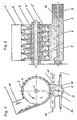
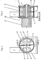
- Figures 1 and 2 show a first embodiment of the invention.
- the device according to the invention for comminuting granular and / or fibrous material has a housing which consists of three parts, namely an insertion shaft 1 for the material to be comminuted, a rotor housing 2 and a conveyor element housing 3.
- a rotor 4 which is driven by a motor, for example, via a PTO shaft, not shown.
- a motor for example an internal combustion engine or an electric motor.
- On the rotor 4 are “wobbling” to the rotor axis 4 ' Saw discs 5 arranged. By “wobbling” it is meant that the saw discs 5 are not perpendicular to the axis 4 'of the rotor 4.
- the insertion shaft 1 extends approximately tangentially to the rotor 4 from top to bottom and is designed such that the granular and / or fibrous material to be shredded, such as sticks, stems, stalks or twigs, can be thrown into it or introduced by means of a conveyor belt.
- a press screw 8 which compresses the material falling into the screw into a briquette strand 9 and expels the briquette strand.
- the shaft 10 of the press screw 8 extends beyond the end of the actual press screw 8, so that a tube remains in the ejected briquette strand, which promotes post-drying or burning.
- the housing 3 has four pipe sockets 12, 13, 14 and 15. Warm air or gas (arrow 16) can enter through the line connector 12 and dry the machined material. These gases can emerge again in cross flow through the nozzle 13 or through the insertion shaft 1.
- One or more additives can be introduced through the connecting pieces 14 and 15, as is known for compression or briquetting: For example, ammonia lactate and briquettes intended for combustion can be used in the production of briquettes intended for combustion be added.
- the exemplary embodiment of the invention described above is particularly suitable without restriction if wood and other biological waste is to be minced very finely and removed via a perforated screen.
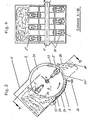
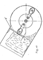
- FIGS. 3 and 4 show a second exemplary embodiment of the invention, which is particularly suitable for milling into the crop, but of course its use is not restricted to this.
- Knives 22 are attached to the disks 21 and slit the straw bale so that the saw blades 5 'can more easily remove the crop in uniform strips.
- An adjustable wedge 23 is also provided, which acts as a counter cutting edge to the toothed tools, i.e. the saw blades works.
- part 24 of the housing 2, on which the strips 6 are attached by means of a hinge 5 on the housing 2 . articulated and supported by a spring 26 so that it can avoid foreign bodies when passing through.
- the comminuted material in this exemplary embodiment is not compressed by means of a press screw and transported to the next processing station; rather, in the second exemplary embodiment, an ejection channel 3 'which can be closed with a flap 20 and a lateral ejection opening (not shown in detail) are provided in the rotor housing 2, through which the comminuted material exits when the ejection channel 3' is closed by means of the flap 20 (position 20 ') .
- the saw blades 5 'protrude beyond the disks 21 only by tooth depth s the saw blades can only take a maximum of one layer thickness of the stalk material corresponding to the tooth depth. Due to the wobbling arrangement of the saw blades 5 ', their working width corresponds to the projection in the direction of rotation of the arch of the blade projecting beyond the disks 21. As a result, and by means of the strips 6 (FIG. 6) arranged offset in a V-shape, an oscillating preparation path 27 is forced, which leads to a uniform comminution of the stalk material.
- a helical covering of the inner wall of the housing 2 with strips offset with respect to one another can be provided, which effects an axial transport of the goods.
- the comminuted material then exits through a lateral opening in the housing, not shown.
- FIG. 7 shows an embodiment in which, in addition to the helically extending strips 6 ', strips 6 "are placed axially parallel.
- the strips 6"' leave a gap in the direction of flow of the material indicated by an arrow 16 18 to the next bar 6 'free; in addition, the strips 6 "'are inclined to the axis parallel, so that the material can flow off and no blockages can occur with fibrous nature.
- the strips can be designed in the same way as the tools of the rotor as cutting, tear, squeeze or grinding strips. It is advantageous if the tools work more cutting or tearing at the beginning of the preparation path and more rubbing or grinding towards the end, since this means that fibrous material is first shredded and the shredded material is then brought to the desired size.
- the material to be comminuted can not only be guided and comminuted in this way on a segment of a circle, but rather it can also be opened a helical path on which it goes through various shredding stages. Furthermore, it is possible to guide the material to be shredded on several circular tracks, the material can only pass from one lane to the next if it fulfills certain conditions, for example in terms of size. Examples of this are given below in connection with FIGS. 9 f. discussed.
- FIG. 9a schematically shows a comminution device, which in turn has an insertion shaft 1 as a feed element, a rotor 4 with a rotor housing 2 and an ejector 3 as an ejection element.
- the inner wall of the rotor housing 2 is covered with strips, which serve to guide the material to be shredded and as a "shear bar" for the shredding tools of the rotor 4.
- strips which serve to guide the material to be shredded and as a "shear bar" for the shredding tools of the rotor 4.
- FIGS. 9b to 9d show examples of the guide and cutting strips 6 on the inner wall of the rotor housing.
- FIG. 9b shows a possible occupancy of the inner wall of the rotor housing 2.
- Section a is covered with arrow-shaped strips 51, section b with arrow-shaped teeth 52 whose profile depth is less than that of strips 51.
- the material entering through the opening between the chute 1 and the rotor housing 2 is roughly crushed in area a and finely in area b.
- area c which has no strips, the material is greatly accelerated and ejected by the tools of the rotor 4. If the profile 52 were to extend to the ejection opening, the ejection speed would be too low in many cases.
- FIG. 9c shows another pattern of a stepped profiling.
- the coarsely inclined ledges 53 bring the good to the right (i.e. upwards in FIG. 9c) when viewed in the direction of flow, while the fine toothed ledges 54 bring the good to the left and then again to the center.
- Smooth channels 55 are provided on the side housing walls, so that a radial flow of the material to be comminuted occurs. In section c the goods are accelerated to circumferential speed and ejected.
- the strip arrangement shown in FIG. 9c leads to a more oscillating movement of the material to be shredded and thus to an overall longer processing path.
- FIG. 9d shows a further possible strip arrangement, in which the amplitude of the oscillating movement of the material on the middle processing path is also greater than in the strip arrangement shown in FIG. 9b.
- Two strips 56 and 57 are arranged in a V-shaped overlap with a distance a from one another.
- FIGS. 9b to 9d show exemplary embodiments in which the profile of the strip arrangement decreases in stages in the flow direction.
- the profile depth can also decrease steadily, which is particularly easy in terms of production technology if a cast housing is used.
- FIGS. 10 to 12 show an example of a comminution device according to the invention with two processing paths, which are circular in the middle, the material to be comminuted being transferred from a first path 61 to a second path 62 through inclined strips 68 ′ (FIGS. 12a and 12b).
- the comminution device in turn consists of a feed chute '1, a rotor housing 2 with a rotor 4 and an ejection element, not shown in detail.
- the rotor 4 is driven by a motor 73 and carries comminuting suspension tools 76 and 77, between which a disk 78 rotating with the rotor is attached to the rotor 4.
- the inner wall of the rotor housing 2 has a web 80 opposite the disk 78.
- the rotor 4 carries closed bodies 79 and 79 in the areas between the tools 76 and 77: together with baffle surfaces 84 and 84 ', the closed bodies reflect the material thrown against them by the tools 16 and 17. Furthermore, together with the circular segments 85 and 85 ', they reflect the material that rebounds inwards from the strips 75 or the profiling. There is a gap s between the circular segments 85 and 85 'through which foreign bodies which cannot be comminuted can be discharged.
- FIGS. 12a and 12b show in detail, the good will follow paths 21 and 22 in the direction of the arrow on average.
- the profiling of the individual strips is carried out in stages, the covering with coarse strips 68 being followed by an assignment with finer strips.
- the covering with fine strips 69 is followed by an outwardly facing strip profile 87 so that the material can exit through a side opening.
- the strips 68 are designed so that they - as already said - the goods from path 61 in the Cross path 62.
- the comminution device described in connection with FIGS. 10 to 12 can be used, for example, for comminuting maize kernel-spindle mixture.
- the approximately circular preparation paths 21 and 22, which are spaced apart in the axial direction, ensure that more than 80% of the material is less than 2 mm in particle size when comminuting corn kernel-spindle mixture.
- the reason for this result which cannot be achieved with known shredding devices or can only be achieved with several shredding processes, is the defined preparation path which is achieved by the strip covering according to the invention.
- the separating strips or disks provided in the device according to the invention prevent the passage of insufficiently comminuted material between two processing paths.
- Another advantage of the slat layout provided according to the invention is that the processing path "just so land" can be chosen so that the desired shredding result is achieved without too much time and without unnecessary energy consumption.
- the shredding tools designed according to the invention i.e.
- the combination of the tools of the rotor provided according to the invention with the strips provided on the inner wall of the rotor housing allows the supply elements for the material to be shredded to be designed as well as the ejection elements which are adapted to the respective material to be shredded and the desired material size and constructional circumstances.
- FIG. 13 shows an exemplary embodiment in which the support disks are replaced or supplemented by a rake 9 '.
- rollers 29 are arranged in the insertion shaft 1 for comminuting round bales 28.
- the round bales are rotated by the cutting forces of the toothed tools and milled in layers according to the tooth depth on the circumference.
- the entrainment and thus the turning of the round bale 28, which rests on the rotating disks 21, is reinforced by teeth 30 on the circumference of the disks 21.
- the rotation of the round bale causes it to rest on the rollers 29 with less weight and to rotate more easily.
- the rotation of the round bale 28 results in a more uniform milling and thus a more uniform crushing result than with untwisted material.
- the discharge duct 3 is contracted to the usual blower opening.
- the comminuted material can be conveyed to a silo, for example, via a subsequent pipeline (not shown).
- FIG. 17 shows a further possibility of discharging the comminuted material.
- the comminuted material exits through an opening 20 ′′ in the bottom of the rotor housing 2 into a pipeline 31, the suction and the further transport of the material being effected by known means, for example by means of an injector sluice.
- Embodiments have been used small wobbling saw blades 5 'separated from disks 21. Instead of small saw blades 5 ', it is of course also possible to use large saw discs as in the first exemplary embodiment described in connection with FIGS. 1 and 2.
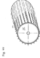
- the drum shown in FIG. 18 with teeth attached is to be preferred in particular if the material to be shredded consists of comparatively large woody plants etc., since the mechanical strength of a cutting device designed as a drum is greater than that of individual saw blades with supporting disks arranged in between.
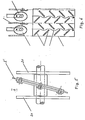
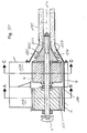
- FIGS. 19 and 20 show a further possibility of increasing the mechanical strength of the cutting device of a shredding device according to the invention and thus of making the device according to the invention usable for shredding comparatively large trees.
- Saw disks 5 are staggering on the rotor 4, between which there are spacer disks 34 which are exceeded by the saw disks 5 by tooth depth s. Furthermore, a positive guide 35 is provided in the insertion shaft, by means of which it is achieved that the woody plants can only be thrown in vertically.
- the adjustable wedge 23 already used in the previously described exemplary embodiments can in turn be used to adjust the degree of fineness of the machining and to adjust the intensity of the retraction of the rod to be shredded.
- FIGS. 19 and 20 has the advantage over the drum 32 shown in FIG. 18 that, if individual teeth are damaged, only the respective saw discs 5, but not the entire drum 32, must be replaced.
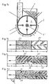
- FIGS. 21 to 24 show a further exemplary embodiment for a rotor according to the invention.
- This rotor is constructed similarly to that shown in FIGS. 19 and 20. Due to the special arrangement of the saw discs, the material is drawn in particularly evenly.
- the rotor with vertical axis 4 ' has two saw discs 5' and 5 ", which are inclined differently to the axis and are arranged eccentrically. With a clockwise rotation, the disc 5 'with the eccentricity e1 is forward and the disc 5" with the Eccentricity e2 offset to the rear.
- the strips 6 are designed so that they hold the good against the rotor. As a result, the material located between the housing wall 2 and the rotor 4 is milled in and drawn in downward.
- the housing bears an inclined feed channel 1 'for trees with a thickness of up to about 8 cm. These woods are also drawn in automatically due to the position of the panes. (Instead of the saw discs shown, the rotor can also carry appropriately adjusted fine teeth.
- FIGS. 23 and 24 show a modification of the embodiment shown in FIGS. 21 and 22 with a conical base body 4. This embodiment is particularly suitable for thick trees etc.
- the collar s prevents the goods from being supported on the housing base.
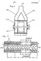
- the area e in front of the ejection opening f (FIG. 27) remains free of the strip occupancy.
- the material is discharged into the ejection tube 117 on the smooth outer surface of the region e hurls.
- A may both sides ufrungsrotoren arranged 113 and 114 ( Figure 28).
- the material is guided to both sides through the inclined strips 118, processed and thrown away.
- the ejection supports 115, 116 on both sides combine to form the ejection tube 117.
- Figures 30f show a combined shredding and pressing device for woody plants and vegetable matter.
- the shaft 4 ' carries a knife drum 121, the rotor 4 with oscillating cutting and tearing tools and a screw press 125.
- the jacket 2 surrounds these organs.
- Woody plants are fed to the knife drum through the channel 127, finer material to the rotor 4 through the channel 128.
- the inside of the jacket is again covered with strips 6 and 6 '.
- the arrow-shaped arrangement of the strips in cooperation with the rotating tools, results in an axial transport of goods.
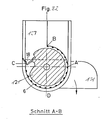
- the arrow-shaped strip arrangement according to FIG. 31 remains parallel to the wall in area I of sector C-A; in sector A-B, the strips 6 axially guide the material into the area of the rotor 4.
- the introduced branches, leaves or grass are broken up at the leading edge C and shredded in the sector CD, which is covered with strips. A further shredding in this sector is also experienced in the goods that have entered area I.
- the ejection flap 131 When the ejection flap 131 is open, the re-shredded material in sector DA of area 131 is ejected again and fed to the press 125 when the flap is closed.
- the rotating pressing body 134 which is provided with worm threads 132 and a thread profile 133, conveys the material into the pressing channel 135. Fine and sufficiently dry Material is compressed into durable briquettes, green grass is squeezed out, and the juice can escape through perforations 137.
- the knife drum and the rotor are driven by a hollow shaft and the screw by a solid shaft passing through it.
- This arrangement has the additional advantage that a web 140 can be drawn in between the second shredding device and the screw press. This avoids costly flying storage of the screw press.
Landscapes
- Engineering & Computer Science (AREA)
- Food Science & Technology (AREA)
- Life Sciences & Earth Sciences (AREA)
- Environmental Sciences (AREA)
- Manufacturing & Machinery (AREA)
- Mechanical Engineering (AREA)
- Wood Science & Technology (AREA)
- Forests & Forestry (AREA)
- Crushing And Pulverization Processes (AREA)
Priority Applications (1)
| Application Number | Priority Date | Filing Date | Title |
|---|---|---|---|
| AT85101014T ATE47969T1 (de) | 1984-01-31 | 1985-01-31 | Vorrichtung zum zerkleinern von koernigen und/oder faserigem gut. |
Applications Claiming Priority (12)
| Application Number | Priority Date | Filing Date | Title |
|---|---|---|---|
| DE19843403200 DE3403200A1 (de) | 1984-01-31 | 1984-01-31 | Kombinierte zerkleinerungseinrichtung fuer gehoelze und gartenabfaelle |
| DE3403200 | 1984-01-31 | ||
| DE3403201 | 1984-01-31 | ||
| DE19843403201 DE3403201A1 (de) | 1984-01-31 | 1984-01-31 | Kombinierte zerkleinerungs- und presseinrichtung fuer gehoelze und pflanzliche stoffe |
| DE3410338 | 1984-03-21 | ||
| DE19843410339 DE3410339A1 (de) | 1984-03-21 | 1984-03-21 | Fraese zum zerspanen von gehoelzen |
| DE19843410338 DE3410338A1 (de) | 1984-03-21 | 1984-03-21 | Einrichtung zur faserigen zerkleinerung von halmgut |
| DE3410339 | 1984-03-21 | ||
| DE3444502 | 1984-12-06 | ||
| DE19843444504 DE3444504A1 (de) | 1984-12-06 | 1984-12-06 | Zerkleinerungseinrichtung mit gestuftem aufbereitungspfad |
| DE19843444502 DE3444502A1 (de) | 1984-12-06 | 1984-12-06 | Einrichtung zum zerkleinern und aufbereiten von halmgut insbesondere von silomais |
| DE3444504 | 1984-12-06 |
Publications (3)
| Publication Number | Publication Date |
|---|---|
| EP0164489A2 true EP0164489A2 (fr) | 1985-12-18 |
| EP0164489A3 EP0164489A3 (en) | 1986-07-30 |
| EP0164489B1 EP0164489B1 (fr) | 1989-11-15 |
Family
ID=27544362
Family Applications (1)
| Application Number | Title | Priority Date | Filing Date |
|---|---|---|---|
| EP85101014A Expired EP0164489B1 (fr) | 1984-01-31 | 1985-01-31 | Dispositif pour le broyage de matériau granuleux et/ou fibreux |
Country Status (2)
| Country | Link |
|---|---|
| EP (1) | EP0164489B1 (fr) |
| DE (1) | DE3574231D1 (fr) |
Cited By (24)
| Publication number | Priority date | Publication date | Assignee | Title |
|---|---|---|---|---|
| DE3615151A1 (de) * | 1986-05-05 | 1987-11-12 | Wieneke Franz | Anbauhaecksler fuer maehdrescher |
| DE3717571C1 (en) * | 1987-05-25 | 1988-06-23 | Maier B Maschf Gmbh Co Kg | Disintegrating machine having a rotor |
| EP0331784A1 (fr) * | 1988-03-10 | 1989-09-13 | Franz Prof. Dr.-Ing. Wieneke | Hacheur de récolte |
| EP0538599A2 (fr) * | 1991-10-24 | 1993-04-28 | Biso B.V. | Hacheuse |
| FR2718605A1 (fr) * | 1994-04-15 | 1995-10-20 | Lucas Sa G | Rotor de démélage et de déchequitage de produits agricoles conditionnés en balles. |
| WO1999048609A3 (fr) * | 1998-03-26 | 1999-12-23 | Rolf Hesch | Dispositif et procede pour effectuer une desagregation prealable de plantes fibreuses et raccourcir ces dernieres, et pour separer des fibres et des fragments de bois |
| EP1010465A1 (fr) * | 1998-12-18 | 2000-06-21 | Pallmann Maschinenfabrik Gmbh + Co. Kg | Elément pour surface de broyage sous forme de tambour |
| EP1161998A1 (fr) * | 2000-06-06 | 2001-12-12 | Turner Development Limited | Broyeur |
| EP1219163A1 (fr) * | 2000-12-20 | 2002-07-03 | Deere & Company | Dispositif hacheur |
| FR2832288A1 (fr) * | 2001-11-22 | 2003-05-23 | Alain Bon | Dispositif de hachage pour ensileuse |
| DE202011103394U1 (de) | 2011-07-19 | 2011-09-07 | Rematec Gmbh & Co. Kg | Mühle zur Zerkleinerung von Mahlgut |
| CN104043512A (zh) * | 2013-03-12 | 2014-09-17 | 丹东天和实业有限公司 | 一种无盲点的精粉碎机 |
| CN104275235A (zh) * | 2013-12-18 | 2015-01-14 | 丁奇 | 一种农作物秸秆粉碎机 |
| CN105123157A (zh) * | 2015-08-13 | 2015-12-09 | 徐州市贾汪区泰瑞农业科技有限公司 | 一种秸秆粉碎车 |
| GB2535174A (en) * | 2015-02-10 | 2016-08-17 | Kverneland Group Kerteminde As | Plant processing apparatus |
| CN109012959A (zh) * | 2018-08-01 | 2018-12-18 | 盛世瑶兰(深圳)科技有限公司 | 一种生物能源用高效果壳破碎装置及其果壳粉碎系统 |
| CN109365072A (zh) * | 2018-09-26 | 2019-02-22 | 黄风山 | 应用于园林废弃物枝叶分离粉碎处理设备 |
| CN112056100A (zh) * | 2020-07-24 | 2020-12-11 | 安徽省厚博生态农业有限公司 | 一种草莓废弃秸秆的处理装置 |
| CN112106536A (zh) * | 2020-10-26 | 2020-12-22 | 黔西南正胤活性炭科技有限公司 | 一种用于活性炭基料制备的秸秆粉碎机 |
| CN112742538A (zh) * | 2020-12-29 | 2021-05-04 | 浙江林龙物流有限公司 | 一种砂石破碎机 |
| CN114986640A (zh) * | 2022-06-07 | 2022-09-02 | 江西绿聚科技有限公司 | 一种消费后回收材料处理木材碾碎装置 |
| CN115400671A (zh) * | 2022-06-29 | 2022-11-29 | 青岛花帝食品配料有限公司 | 一种生物复合调味料用搅拌混合装置 |
| CN115970837A (zh) * | 2023-01-04 | 2023-04-18 | 李海波 | 一种固废资源化处理用多级破碎装置及破碎方法 |
| CN117427745A (zh) * | 2023-12-15 | 2024-01-23 | 中城院(北京)环境科技股份有限公司 | 一种适用于多元物料快速腐殖化系统的预处理粉碎装置 |
Families Citing this family (4)
| Publication number | Priority date | Publication date | Assignee | Title |
|---|---|---|---|---|
| CN104475208B (zh) * | 2014-11-19 | 2016-08-31 | 苏州市高凡生物科技有限公司 | 用于有机垃圾处理系统的切割装置 |
| CN108247785B (zh) * | 2018-01-18 | 2019-07-19 | 江西红锦发木业有限公司 | 一种高密度木板的木质碎料原料浸泡加工装置 |
| CN108353657B (zh) * | 2018-03-26 | 2020-05-05 | 重庆洛瀚商贸有限公司 | 秸秆粉碎装置 |
| CN111328566B (zh) * | 2020-03-07 | 2022-01-04 | 李作冷 | 一种牧草分切碎料设备 |
Citations (8)
| Publication number | Priority date | Publication date | Assignee | Title |
|---|---|---|---|---|
| DE268364C (fr) * | ||||
| US601712A (en) * | 1898-04-05 | Shredder | ||
| US1281598A (en) * | 1916-01-31 | 1918-10-15 | Letz Mfg Co | Hay-cutter. |
| CH266380A (de) * | 1947-08-22 | 1950-01-31 | Oswald Dr Wyss | Verfahren zur Gewinnung von verfilzbaren Holzfasern zur Erzeugung von Formkörpern. |
| DE1403858A1 (fr) * | 1960-04-08 | 1970-08-06 | ||
| CH544581A (de) * | 1971-08-06 | 1973-11-30 | Haeberle Wilhelm | Schneidmühle |
| DE2240689B2 (de) * | 1972-08-18 | 1978-07-06 | 7988 Wangen | Vorrichtung zum Zerkleinern und Weiterfördern von in kompakter Form zugeführten Massen wie Filterkuchen |
| DE3324467A1 (de) * | 1983-07-07 | 1985-01-24 | Franz Prof.Dr.-Ing. 3406 Bovenden Wieneke | Zerkleinerungseinrichtung fuer koerniges und faseriges gut sowie halmgut |
-
1985
- 1985-01-31 DE DE8585101014T patent/DE3574231D1/de not_active Expired
- 1985-01-31 EP EP85101014A patent/EP0164489B1/fr not_active Expired
Patent Citations (8)
| Publication number | Priority date | Publication date | Assignee | Title |
|---|---|---|---|---|
| DE268364C (fr) * | ||||
| US601712A (en) * | 1898-04-05 | Shredder | ||
| US1281598A (en) * | 1916-01-31 | 1918-10-15 | Letz Mfg Co | Hay-cutter. |
| CH266380A (de) * | 1947-08-22 | 1950-01-31 | Oswald Dr Wyss | Verfahren zur Gewinnung von verfilzbaren Holzfasern zur Erzeugung von Formkörpern. |
| DE1403858A1 (fr) * | 1960-04-08 | 1970-08-06 | ||
| CH544581A (de) * | 1971-08-06 | 1973-11-30 | Haeberle Wilhelm | Schneidmühle |
| DE2240689B2 (de) * | 1972-08-18 | 1978-07-06 | 7988 Wangen | Vorrichtung zum Zerkleinern und Weiterfördern von in kompakter Form zugeführten Massen wie Filterkuchen |
| DE3324467A1 (de) * | 1983-07-07 | 1985-01-24 | Franz Prof.Dr.-Ing. 3406 Bovenden Wieneke | Zerkleinerungseinrichtung fuer koerniges und faseriges gut sowie halmgut |
Cited By (34)
| Publication number | Priority date | Publication date | Assignee | Title |
|---|---|---|---|---|
| DE3615151A1 (de) * | 1986-05-05 | 1987-11-12 | Wieneke Franz | Anbauhaecksler fuer maehdrescher |
| DE3717571C1 (en) * | 1987-05-25 | 1988-06-23 | Maier B Maschf Gmbh Co Kg | Disintegrating machine having a rotor |
| EP0331784A1 (fr) * | 1988-03-10 | 1989-09-13 | Franz Prof. Dr.-Ing. Wieneke | Hacheur de récolte |
| EP0538599A2 (fr) * | 1991-10-24 | 1993-04-28 | Biso B.V. | Hacheuse |
| EP0538599A3 (en) * | 1991-10-24 | 1994-06-22 | Biso Maschf Gmbh | Chopper |
| FR2718605A1 (fr) * | 1994-04-15 | 1995-10-20 | Lucas Sa G | Rotor de démélage et de déchequitage de produits agricoles conditionnés en balles. |
| US6719225B1 (en) | 1998-03-26 | 2004-04-13 | Rolf Hesch | Device and method for pre-disintegrating and cutting into sections fibrous plants and for the separation of fibers and woody parts |
| WO1999048609A3 (fr) * | 1998-03-26 | 1999-12-23 | Rolf Hesch | Dispositif et procede pour effectuer une desagregation prealable de plantes fibreuses et raccourcir ces dernieres, et pour separer des fibres et des fragments de bois |
| EP1010465A1 (fr) * | 1998-12-18 | 2000-06-21 | Pallmann Maschinenfabrik Gmbh + Co. Kg | Elément pour surface de broyage sous forme de tambour |
| EP1161998A1 (fr) * | 2000-06-06 | 2001-12-12 | Turner Development Limited | Broyeur |
| EP1219163A1 (fr) * | 2000-12-20 | 2002-07-03 | Deere & Company | Dispositif hacheur |
| US6688971B2 (en) | 2000-12-20 | 2004-02-10 | Deere & Company | Chopper arrangement |
| FR2832288A1 (fr) * | 2001-11-22 | 2003-05-23 | Alain Bon | Dispositif de hachage pour ensileuse |
| DE202011103394U1 (de) | 2011-07-19 | 2011-09-07 | Rematec Gmbh & Co. Kg | Mühle zur Zerkleinerung von Mahlgut |
| EP2548648A2 (fr) | 2011-07-19 | 2013-01-23 | Rematec GmbH & Co. KG | Broyeur pour le broyage de matière |
| EP2548648A3 (fr) * | 2011-07-19 | 2014-03-12 | Rematec GmbH & Co. KG | Broyeur pour le broyage de matière |
| CN104043512A (zh) * | 2013-03-12 | 2014-09-17 | 丹东天和实业有限公司 | 一种无盲点的精粉碎机 |
| CN104275235A (zh) * | 2013-12-18 | 2015-01-14 | 丁奇 | 一种农作物秸秆粉碎机 |
| GB2535174A (en) * | 2015-02-10 | 2016-08-17 | Kverneland Group Kerteminde As | Plant processing apparatus |
| GB2535174B (en) * | 2015-02-10 | 2020-10-21 | Kverneland Group Kerteminde As | Plant processing apparatus |
| CN105123157A (zh) * | 2015-08-13 | 2015-12-09 | 徐州市贾汪区泰瑞农业科技有限公司 | 一种秸秆粉碎车 |
| CN109012959A (zh) * | 2018-08-01 | 2018-12-18 | 盛世瑶兰(深圳)科技有限公司 | 一种生物能源用高效果壳破碎装置及其果壳粉碎系统 |
| CN109365072A (zh) * | 2018-09-26 | 2019-02-22 | 黄风山 | 应用于园林废弃物枝叶分离粉碎处理设备 |
| CN112056100A (zh) * | 2020-07-24 | 2020-12-11 | 安徽省厚博生态农业有限公司 | 一种草莓废弃秸秆的处理装置 |
| CN112106536A (zh) * | 2020-10-26 | 2020-12-22 | 黔西南正胤活性炭科技有限公司 | 一种用于活性炭基料制备的秸秆粉碎机 |
| CN112742538A (zh) * | 2020-12-29 | 2021-05-04 | 浙江林龙物流有限公司 | 一种砂石破碎机 |
| CN114986640A (zh) * | 2022-06-07 | 2022-09-02 | 江西绿聚科技有限公司 | 一种消费后回收材料处理木材碾碎装置 |
| CN114986640B (zh) * | 2022-06-07 | 2023-06-02 | 江西绿聚科技有限公司 | 一种消费后回收材料处理木材碾碎装置 |
| CN115400671A (zh) * | 2022-06-29 | 2022-11-29 | 青岛花帝食品配料有限公司 | 一种生物复合调味料用搅拌混合装置 |
| CN115400671B (zh) * | 2022-06-29 | 2023-11-07 | 青岛花帝食品配料有限公司 | 一种生物复合调味料用搅拌混合装置 |
| CN115970837A (zh) * | 2023-01-04 | 2023-04-18 | 李海波 | 一种固废资源化处理用多级破碎装置及破碎方法 |
| CN115970837B (zh) * | 2023-01-04 | 2023-11-10 | 深圳市九夏泰禾环境科技有限公司 | 一种固废资源化处理用多级破碎装置及破碎方法 |
| CN117427745A (zh) * | 2023-12-15 | 2024-01-23 | 中城院(北京)环境科技股份有限公司 | 一种适用于多元物料快速腐殖化系统的预处理粉碎装置 |
| CN117427745B (zh) * | 2023-12-15 | 2024-04-26 | 中城院(北京)环境科技股份有限公司 | 一种适用于多元物料快速腐殖化系统的预处理粉碎装置 |
Also Published As
| Publication number | Publication date |
|---|---|
| EP0164489B1 (fr) | 1989-11-15 |
| DE3574231D1 (en) | 1989-12-21 |
| EP0164489A3 (en) | 1986-07-30 |
Similar Documents
| Publication | Publication Date | Title |
|---|---|---|
| EP0164489B1 (fr) | Dispositif pour le broyage de matériau granuleux et/ou fibreux | |
| DE4036717A1 (de) | Pflueckvorsatz fuer ein erntegeraet | |
| DE2831309A1 (de) | Schlagentspelzer | |
| DD225323A1 (de) | Schneidwurftrommel fuer ein haeckselaggregat | |
| DE2517131C2 (de) | Vorrichtung zum Auflockern von feuchten, faserhaltigen Materialien | |
| DE3234657C2 (fr) | ||
| EP0124138B1 (fr) | Méthode et dispositif pour le broyage de produits végétaux | |
| DE2754722A1 (de) | Verfahren und vorrichtung zum behandeln von mais | |
| DE2062945C3 (de) | Maiserntegerät | |
| DE3125309C2 (de) | Zerkleinerungsvorrichtung für Abfälle | |
| EP0153621A1 (fr) | Hacheuse à tambour avec une broyeuse secondaire | |
| WO2005041639A1 (fr) | Dispositif de hachage pour moissonneuse-batteuse | |
| DE3607021A1 (de) | Maschine zum zerkleinern von holzstuecken | |
| EP0156128B1 (fr) | Broyeuse secondaire pour paille hachée | |
| EP1782680B1 (fr) | Dispositif pour le broyage de produits végétaux dans la forme de masse verte ou de jeunes buissons | |
| DE4200592A1 (de) | Zerkleinerungsvorrichtung für Gehölze sowie Halm- und Blattgut | |
| DE3201651A1 (de) | Zerkleinerungsmaschine mit einem rotierenden behaelter | |
| DE19548883C2 (de) | Langsamlaufender Gartenhäcksler | |
| DE3345919C2 (fr) | ||
| DE3321449A1 (de) | Zerkleinerungsmaschine, insbesondere zur zerkleinerung von futterstoffen | |
| EP0108262B1 (fr) | Dispositif pour le traitement de déchets | |
| DE2526211A1 (de) | Zufuehrvorrichtung fuer eine zerkleinerungsmaschine | |
| DE3612997A1 (de) | Maschine zum zerkleinern von holzstuecken und dergleichen | |
| DE2422894A1 (de) | Haeckselmaschine | |
| DE3630742C2 (fr) |
Legal Events
| Date | Code | Title | Description |
|---|---|---|---|
| PUAI | Public reference made under article 153(3) epc to a published international application that has entered the european phase |
Free format text: ORIGINAL CODE: 0009012 |
|
| AK | Designated contracting states |
Designated state(s): AT BE CH DE FR GB IT LI LU NL SE |
|
| PUAL | Search report despatched |
Free format text: ORIGINAL CODE: 0009013 |
|
| AK | Designated contracting states |
Kind code of ref document: A3 Designated state(s): AT BE CH DE FR GB IT LI LU NL SE |
|
| 17P | Request for examination filed |
Effective date: 19870130 |
|
| RBV | Designated contracting states (corrected) |
Designated state(s): AT CH DE FR LI SE |
|
| 17Q | First examination report despatched |
Effective date: 19871201 |
|
| GRAA | (expected) grant |
Free format text: ORIGINAL CODE: 0009210 |
|
| AK | Designated contracting states |
Kind code of ref document: B1 Designated state(s): AT CH DE FR LI SE |
|
| REF | Corresponds to: |
Ref document number: 47969 Country of ref document: AT Date of ref document: 19891215 Kind code of ref document: T |
|
| REF | Corresponds to: |
Ref document number: 3574231 Country of ref document: DE Date of ref document: 19891221 |
|
| ET | Fr: translation filed | ||
| PLBE | No opposition filed within time limit |
Free format text: ORIGINAL CODE: 0009261 |
|
| STAA | Information on the status of an ep patent application or granted ep patent |
Free format text: STATUS: NO OPPOSITION FILED WITHIN TIME LIMIT |
|
| 26N | No opposition filed | ||
| PGFP | Annual fee paid to national office [announced via postgrant information from national office to epo] |
Ref country code: FR Payment date: 19921221 Year of fee payment: 9 |
|
| PGFP | Annual fee paid to national office [announced via postgrant information from national office to epo] |
Ref country code: CH Payment date: 19921223 Year of fee payment: 9 |
|
| PGFP | Annual fee paid to national office [announced via postgrant information from national office to epo] |
Ref country code: AT Payment date: 19930114 Year of fee payment: 9 |
|
| PGFP | Annual fee paid to national office [announced via postgrant information from national office to epo] |
Ref country code: SE Payment date: 19930126 Year of fee payment: 9 |
|
| PG25 | Lapsed in a contracting state [announced via postgrant information from national office to epo] |
Ref country code: LI Effective date: 19940131 Ref country code: CH Effective date: 19940131 Ref country code: AT Effective date: 19940131 |
|
| PG25 | Lapsed in a contracting state [announced via postgrant information from national office to epo] |
Ref country code: SE Effective date: 19940201 |
|
| PGFP | Annual fee paid to national office [announced via postgrant information from national office to epo] |
Ref country code: DE Payment date: 19940908 Year of fee payment: 10 |
|
| PG25 | Lapsed in a contracting state [announced via postgrant information from national office to epo] |
Ref country code: FR Effective date: 19940930 |
|
| REG | Reference to a national code |
Ref country code: CH Ref legal event code: PL |
|
| REG | Reference to a national code |
Ref country code: FR Ref legal event code: ST |
|
| EUG | Se: european patent has lapsed |
Ref document number: 85101014.0 Effective date: 19940910 |
|
| PG25 | Lapsed in a contracting state [announced via postgrant information from national office to epo] |
Ref country code: DE Effective date: 19951003 |