EP0156247A2 - Plancher creux - Google Patents
Plancher creux Download PDFInfo
- Publication number
- EP0156247A2 EP0156247A2 EP85102859A EP85102859A EP0156247A2 EP 0156247 A2 EP0156247 A2 EP 0156247A2 EP 85102859 A EP85102859 A EP 85102859A EP 85102859 A EP85102859 A EP 85102859A EP 0156247 A2 EP0156247 A2 EP 0156247A2
- Authority
- EP
- European Patent Office
- Prior art keywords
- floor
- cavity
- formwork
- shuttering
- hollow
- Prior art date
- Legal status (The legal status is an assumption and is not a legal conclusion. Google has not performed a legal analysis and makes no representation as to the accuracy of the status listed.)
- Granted
Links
Images

Classifications
-
- E—FIXED CONSTRUCTIONS
- E04—BUILDING
- E04F—FINISHING WORK ON BUILDINGS, e.g. STAIRS, FLOORS
- E04F15/00—Flooring
- E04F15/12—Flooring or floor layers made of masses in situ, e.g. seamless magnesite floors, terrazzo gypsum floors
- E04F15/123—Lost formworks for producing hollow floor screed layers, e.g. for receiving installations, ducts, cables
-
- E—FIXED CONSTRUCTIONS
- E04—BUILDING
- E04F—FINISHING WORK ON BUILDINGS, e.g. STAIRS, FLOORS
- E04F15/00—Flooring
- E04F15/18—Separately-laid insulating layers; Other additional insulating measures; Floating floors
- E04F15/182—Underlayers coated with adhesive or mortar to receive the flooring
-
- E—FIXED CONSTRUCTIONS
- E04—BUILDING
- E04F—FINISHING WORK ON BUILDINGS, e.g. STAIRS, FLOORS
- E04F15/00—Flooring
- E04F15/18—Separately-laid insulating layers; Other additional insulating measures; Floating floors
- E04F15/188—Edge insulation strips, e.g. for floor screed layers
Definitions
- the invention relates to a hollow floor with a sub-floor and a support feet resting on the sub-floor and with this an upper floor enclosing a cavity.
- the top floor is produced by pouring screed, gypsum or a similar flowable mass onto a sheet of formwork that stands on the sub-floor.
- the disadvantage here is that the flowable mass can flow into the cavity of the hollow floor at the formwork edges.
- the invention has for its object to provide a hollow floor of the type mentioned, in which, with quick and easy installation , there is a guarantee that the floor cavity will not be contaminated or blocked by the flowable applied mass of the top floor.
- the cavity delimited by a formwork for the top floor made by cast-in place is laterally closed by profiled strips.
- the profile strips prevent the pouring compound of the top floor from entering the cavity. They are arranged along the edge of the raised floor.
- the casting compound that forms the top floor then creates a solid block between the wall and the cavity of the raised floor, so that no special measures for adapting the mold of the top floor to the side wall of the room are required.
- the profile strips preferably consist of interconnectable modules, the lengths of which are graduated in the grid dimension of the support feet.
- the cavity of the hollow floor serves as a routing space for cables and pipes as a warm air underfloor heating.
- the lower and / or the upper boundary wall of the cavity is provided at least in places with a heat-reflecting coating.
- a coating on the boundary wall of the cavity generally causes the floor temperature to drop at this point. : In this way, the heat distribution in the raised floor can be influenced by targeted distribution of heat-reflecting coatings.
- FIG. 1 of the sub-floor 10 comprises a concrete layer 11 is disposed on the an insulation layer 12, and the insulating layer 12 covering the insulating layer 13 D ruckverteil Mrs 12 serves both the thermal insulation and sound insulation. It can consist of foam, fiber mats or another heat and sound insulating material. Since the insulation layer 12 is relatively soft, the pressure distribution layer 13 made of a harder material is arranged above it. The pressure distribution layer 13 in the present case consists of a perforated steel sheet, the holes of which are designated by 14.
- the top floor consists of a mass of screed, gypsum or the like applied to a lost formwork 17 in a flowable form, which fills the formwork 17 and one for the formwork 17 Load-bearing capacity forms a sufficiently strong layer.
- the formwork 17 consists of a load-bearing plastic film from which the support feet 16 are formed in the manner of an egg carton. Between the support feet 16 are arcuate over gears, so that the vault-like cavity 18 is formed in the top floor 15 between the support feet 16. Air can be directed into this cavity for heating or cooling purposes.
- the formwork 17 has such a load-bearing capacity that it initially carries the mass 19 which is applied in a flowable manner. This mass 19 then hardens and forms the supporting structure of the upper floor 15.
- the support feet 16 taper downwards, their side walls abutting the pressure distribution layer 13 at almost right angles.
- the formwork 17 consists of prefabricated profiled plastic plates which are placed on the pressure distribution layer 13. In order not to have to cut these panels to size so that they each extend up to the side wall 20 of the room or building, a profile strip 21 is laid under the edge of the outermost panel in each case, which laterally delimits the cavity 18. The edge of the formwork 17 is fastened in a sealing manner on this profile strip 21 with an adhesive tape 22. The edge of the pressure distribution layer 13 lying outside the profile strip 21 is covered with a tough pasty mass 23, which covers the holes 14 in this area.
- a block 19 ′ is formed between the wall 20 and the profile strip 21, which projects up to the wall 20.
- the block 19 ' is separated from the wall 20 only by a separating strip 24, which consists of a sound-absorbing material, for example foam. In this way, the transfer of body prevents sound between the top floor 15 and the side wall 20.
- the profile strip 21 consists of components 25 which are rectangular in cross section and have a head-like extension 26 on one end face and a recess 27 adapted to the extension 26 on their opposite end side.
- the blocks 25 can be put together in the manner shown in FIG. 2. They are available in graded lengths, each of which forms an integral multiple of the grid dimension between the support feet 16. In this way, the profile strips 21 can be assembled in the desired length without having to be cut off.
- an insulating layer 32 is arranged on the concrete ceiling 11, which has a section 32 ′ drawn up on the side wall 20.
- the pressure distribution layer 33 consisting of individual prefabricated plates is placed on the insulation layer.
- the pressure distribution layer 33 has a smooth underside and a profiled top.
- Elevations 34 are provided in the top, onto which the downward-facing lugs 35 of the top floor are placed.
- the elevations 34 and the lugs 35 each form a support foot.
- the elevations 34 are each between troughs of the pressure distribution layer 33, so that the cavity 18 is partly formed in the interior of the underbody 10 and another part in the interior of the upper floor 15.
- the tops of the elevations 34 are each surrounded by a centering ring 36, in which an extension 35 of the top plate 15 is centered.
- the projections 35 are omitted and the elevations 34 extend to the flat underside of the top floor.
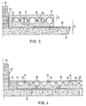
- the edge 37 of the pressure distribution layer 33 facing the side wall 20 is pulled up to the upper limit of the cavity 18 in the embodiment of FIG. 3.
- the end of the formwork 17 is placed on the top of the edge 37 and glued there.
- the space between the edge 37 and the section 32 of the insulation layer resting against the wall 20 is filled with the mass 19 of the top floor 15. This mass extends down to the insulation layer 32 in the space mentioned.
- the sub-floor 10 has a concrete slab 11, which is covered by the insulation layer 32.
- a section 32 ′ of the insulation layer 32 protrudes a little from the wall 20.
- the sub-floor 10 also includes the plates 38, which lie with their flat undersides on the insulation layer 32 and have upstanding support feet 39.
- the upper floor 15 consists of the flat plates 40, which lie on the upper sides of the support feet 39 and whose gaps are sealed by elastic joint seals 41.
- the troughs 42 between the support feet 39, in connection with the plates 40 delimit the cavity 18.
- the cross section of the support feet 39 decreases upwards, so that the vertical contact forces, which are transmitted from the plates 40 to the support feet 39, are relative rigid panels 38 are evenly distributed over the relatively soft insulation layer 32.
- the edge 43 of the outer plate 38 facing the wall 20 forms a continuous edge strip 43.
- the space between the section 32 ′ of the insulation layer 32 abutting the wall 20 and the edge strip 43 is filled with a screed filler 44, on the top of which the outermost plate 40 rests.
- Some of the support feet 39 have centering pieces 45 arranged on their upper side at a spacing of the grid dimension of the plates 40 for centering the edges of the plates 40.
- These plates 40 form the base plates. They consist, for example, of sheet metal with a floor covering attached to it, of ceramic or the like.
- the troughs 46 are coated with a heat-reflecting film 46 in some or all areas of the hollow floor. This film causes heat to be reflected from the sub-floor 10 into the cavity 18, so that the portion of the heat that the. Upper floor 15 is released, is still enlarged.
Priority Applications (1)
| Application Number | Priority Date | Filing Date | Title |
|---|---|---|---|
| AT85102859T ATE39725T1 (de) | 1982-01-15 | 1983-01-14 | Hohlboden. |
Applications Claiming Priority (2)
| Application Number | Priority Date | Filing Date | Title |
|---|---|---|---|
| DE3201085 | 1982-01-15 | ||
| DE19823201085 DE3201085A1 (de) | 1981-02-04 | 1982-01-15 | "hohlboden" |
Related Parent Applications (1)
| Application Number | Title | Priority Date | Filing Date |
|---|---|---|---|
| EP83100285.2 Division | 1983-01-14 |
Publications (3)
| Publication Number | Publication Date |
|---|---|
| EP0156247A2 true EP0156247A2 (fr) | 1985-10-02 |
| EP0156247A3 EP0156247A3 (en) | 1986-07-30 |
| EP0156247B1 EP0156247B1 (fr) | 1989-01-04 |
Family
ID=6153149
Family Applications (2)
| Application Number | Title | Priority Date | Filing Date |
|---|---|---|---|
| EP83100285A Withdrawn EP0085845A1 (fr) | 1982-01-15 | 1983-01-14 | Plancher creux |
| EP85102859A Expired EP0156247B1 (fr) | 1982-01-15 | 1983-01-14 | Plancher creux |
Family Applications Before (1)
| Application Number | Title | Priority Date | Filing Date |
|---|---|---|---|
| EP83100285A Withdrawn EP0085845A1 (fr) | 1982-01-15 | 1983-01-14 | Plancher creux |
Country Status (3)
| Country | Link |
|---|---|
| EP (2) | EP0085845A1 (fr) |
| AT (1) | ATE39725T1 (fr) |
| DE (1) | DE3378835D1 (fr) |
Cited By (2)
| Publication number | Priority date | Publication date | Assignee | Title |
|---|---|---|---|---|
| EP0298325A2 (fr) * | 1987-07-09 | 1989-01-11 | Henkel Kommanditgesellschaft auf Aktien | Garniture à double couche pour planchers creux |
| DE4104979A1 (de) * | 1991-02-19 | 1992-08-27 | Guenther Holzem | Bauelement fuer die herstellung von fussboeden |
Families Citing this family (4)
| Publication number | Priority date | Publication date | Assignee | Title |
|---|---|---|---|---|
| DE3404279A1 (de) * | 1984-02-08 | 1985-08-08 | Mainbau Estrich- und Fußboden GmbH, 8500 Nürnberg | Fussboden- und wandkonstruktion |
| DE3505458A1 (de) * | 1985-02-16 | 1986-08-28 | Mainbau Estrich- und Fußboden GmbH, 8500 Nürnberg | Verfahren zur herstellung eines hohlraumbodens |
| AU589217B2 (en) * | 1985-10-30 | 1989-10-05 | Ronald Raymond Anderson | Building insulation |
| CN208105573U (zh) * | 2017-10-13 | 2018-11-16 | 杭州建格科技有限公司 | 一种墙体系统 |
Citations (5)
| Publication number | Priority date | Publication date | Assignee | Title |
|---|---|---|---|---|
| GB592606A (en) * | 1945-05-11 | 1947-09-23 | Rheinallt Morgan Jones | Improvements relating to constructional blocks |
| CH397205A (de) * | 1960-05-27 | 1965-08-15 | Hinrich Reimers Gmbh | Fussboden für Wohnbauten mit verbesserter Entfeuchtung, Wärmedämmung und Schallisolierung |
| DE1609974A1 (de) * | 1966-07-29 | 1970-07-30 | Gartner & Co J | Begehbare Flachdach- oder Bodenkonstruktion |
| DE2241836A1 (de) * | 1972-08-25 | 1974-03-07 | Mahr Soehne Gmbh Theo | Luftfuehrungs-rohrbatterien fuer fussboden-warmluftheizung |
| DE2703273B1 (de) * | 1977-01-27 | 1978-03-02 | Mahle Gmbh | Abschottung fuer den Raum unterhalb der Trittplatten eines aufgestaenderten Bodens |
-
1983
- 1983-01-14 EP EP83100285A patent/EP0085845A1/fr not_active Withdrawn
- 1983-01-14 AT AT85102859T patent/ATE39725T1/de not_active IP Right Cessation
- 1983-01-14 DE DE8585102859T patent/DE3378835D1/de not_active Expired
- 1983-01-14 EP EP85102859A patent/EP0156247B1/fr not_active Expired
Patent Citations (5)
| Publication number | Priority date | Publication date | Assignee | Title |
|---|---|---|---|---|
| GB592606A (en) * | 1945-05-11 | 1947-09-23 | Rheinallt Morgan Jones | Improvements relating to constructional blocks |
| CH397205A (de) * | 1960-05-27 | 1965-08-15 | Hinrich Reimers Gmbh | Fussboden für Wohnbauten mit verbesserter Entfeuchtung, Wärmedämmung und Schallisolierung |
| DE1609974A1 (de) * | 1966-07-29 | 1970-07-30 | Gartner & Co J | Begehbare Flachdach- oder Bodenkonstruktion |
| DE2241836A1 (de) * | 1972-08-25 | 1974-03-07 | Mahr Soehne Gmbh Theo | Luftfuehrungs-rohrbatterien fuer fussboden-warmluftheizung |
| DE2703273B1 (de) * | 1977-01-27 | 1978-03-02 | Mahle Gmbh | Abschottung fuer den Raum unterhalb der Trittplatten eines aufgestaenderten Bodens |
Cited By (4)
| Publication number | Priority date | Publication date | Assignee | Title |
|---|---|---|---|---|
| EP0298325A2 (fr) * | 1987-07-09 | 1989-01-11 | Henkel Kommanditgesellschaft auf Aktien | Garniture à double couche pour planchers creux |
| EP0298325A3 (fr) * | 1987-07-09 | 1989-07-12 | Henkel Kommanditgesellschaft auf Aktien | Garniture à double couche pour planchers creux |
| US4910935A (en) * | 1987-07-09 | 1990-03-27 | Henkel Kommanditgesellschaft Auf Aktien | Two-layer cavity floor covering |
| DE4104979A1 (de) * | 1991-02-19 | 1992-08-27 | Guenther Holzem | Bauelement fuer die herstellung von fussboeden |
Also Published As
| Publication number | Publication date |
|---|---|
| DE3378835D1 (en) | 1989-02-09 |
| ATE39725T1 (de) | 1989-01-15 |
| EP0085845A1 (fr) | 1983-08-17 |
| EP0156247B1 (fr) | 1989-01-04 |
| EP0156247A3 (en) | 1986-07-30 |
Similar Documents
| Publication | Publication Date | Title |
|---|---|---|
| DE19605142C1 (de) | Fußbodenverbundkörper | |
| DE3431118C1 (de) | Freitragende Verbundbauplatte,insbesondere fuer Doppelboeden | |
| EP0133556A2 (fr) | Elément préfabriquée de coffrage pour constructions de plancher cellulaire | |
| EP0123136B1 (fr) | Structure de revêtement pour chauffage par le sol ou par les murs | |
| DE3231779C2 (de) | Elastisch nachgiebige Sicherheitsbelagsplatte, insbesondere für Spielfelder | |
| DE3201085A1 (de) | "hohlboden" | |
| EP0074490B1 (fr) | Sol avec chauffage intégré par eau chaude | |
| EP1462727B1 (fr) | Dispositif pour la pose de tubes traversés par des fluides réfrigérants ou chauffants d'un système de conditionnement thermique à grande surface | |
| EP0156247B1 (fr) | Plancher creux | |
| DE2307815B2 (de) | Schall- und wärmedämmende Fußbodenplatte | |
| EP1083269B1 (fr) | Aides pour la pose de revêtements en plaques en position surélevée ou ventilée | |
| DE1966975A1 (de) | Wand- oder fussbodenbelagplatte als vorgefertigte installationsplatte mit grundund deckplatte | |
| DE2807890C2 (de) | Doppelbodenplatte | |
| EP0062687B1 (fr) | Elément de plancher nervuré partiellement préfabriqué | |
| EP0015460A1 (fr) | Elément d'appui pour dalles en béton armé ou analogues | |
| AT390465B (de) | Doppelboden mit einer feuerhemmenden schicht | |
| DE20016475U1 (de) | Verkleidungselement | |
| DE3100991C2 (de) | "Tragendes Bauelement für Decken oder Dächer" | |
| EP0300135B1 (fr) | Procédé pour confectionner une chape sur un plancher surélevé | |
| DE2552571A1 (de) | Bodenbeschichtung und eckenabdichtung fuer nassraeume | |
| DE8031457U1 (de) | Fuellkoerper fuer waermedaemmende gebaeudedecken | |
| DE19630433C2 (de) | Hohlraumboden | |
| DE4129760C2 (de) | Hohlraumboden | |
| DE8437422U1 (de) | Randdaemmstreifen | |
| DE4441645A1 (de) | Verfahren zur Herstellung einer Abdeckung für Loggien oder dergleichen |
Legal Events
| Date | Code | Title | Description |
|---|---|---|---|
| PUAI | Public reference made under article 153(3) epc to a published international application that has entered the european phase |
Free format text: ORIGINAL CODE: 0009012 |
|
| AC | Divisional application: reference to earlier application |
Ref document number: 85845 Country of ref document: EP |
|
| AK | Designated contracting states |
Designated state(s): AT BE CH DE FR GB IT LI LU NL SE |
|
| PUAL | Search report despatched |
Free format text: ORIGINAL CODE: 0009013 |
|
| AK | Designated contracting states |
Kind code of ref document: A3 Designated state(s): AT BE CH DE FR GB IT LI LU NL SE |
|
| 17P | Request for examination filed |
Effective date: 19860627 |
|
| 17Q | First examination report despatched |
Effective date: 19870626 |
|
| RAP1 | Party data changed (applicant data changed or rights of an application transferred) |
Owner name: GOLDBACH GMBH Owner name: NORINA BAUTECHNIK GMBH Owner name: SCHMIDT REUTER INGENIEURGESELLSCHAFT MBH & CO. KG |
|
| GRAA | (expected) grant |
Free format text: ORIGINAL CODE: 0009210 |
|
| AC | Divisional application: reference to earlier application |
Ref document number: 85845 Country of ref document: EP |
|
| AK | Designated contracting states |
Kind code of ref document: B1 Designated state(s): AT BE CH DE FR GB IT LI LU NL SE |
|
| REF | Corresponds to: |
Ref document number: 39725 Country of ref document: AT Date of ref document: 19890115 Kind code of ref document: T |
|
| ITF | It: translation for a ep patent filed |
Owner name: ING. A. GIAMBROCONO & C. S.R.L. |
|
| GBT | Gb: translation of ep patent filed (gb section 77(6)(a)/1977) | ||
| REF | Corresponds to: |
Ref document number: 3378835 Country of ref document: DE Date of ref document: 19890209 |
|
| ET | Fr: translation filed | ||
| PLBE | No opposition filed within time limit |
Free format text: ORIGINAL CODE: 0009261 |
|
| STAA | Information on the status of an ep patent application or granted ep patent |
Free format text: STATUS: NO OPPOSITION FILED WITHIN TIME LIMIT |
|
| 26N | No opposition filed | ||
| ITTA | It: last paid annual fee | ||
| EPTA | Lu: last paid annual fee | ||
| PGFP | Annual fee paid to national office [announced via postgrant information from national office to epo] |
Ref country code: SE Payment date: 19941230 Year of fee payment: 13 |
|
| PGFP | Annual fee paid to national office [announced via postgrant information from national office to epo] |
Ref country code: CH Payment date: 19950130 Year of fee payment: 13 |
|
| EAL | Se: european patent in force in sweden |
Ref document number: 85102859.7 |
|
| PG25 | Lapsed in a contracting state [announced via postgrant information from national office to epo] |
Ref country code: SE Effective date: 19960115 |
|
| PG25 | Lapsed in a contracting state [announced via postgrant information from national office to epo] |
Ref country code: LI Effective date: 19960131 Ref country code: CH Effective date: 19960131 |
|
| REG | Reference to a national code |
Ref country code: CH Ref legal event code: PL |
|
| EUG | Se: european patent has lapsed |
Ref document number: 85102859.7 |
|
| PGFP | Annual fee paid to national office [announced via postgrant information from national office to epo] |
Ref country code: GB Payment date: 19970207 Year of fee payment: 15 |
|
| PGFP | Annual fee paid to national office [announced via postgrant information from national office to epo] |
Ref country code: FR Payment date: 19970217 Year of fee payment: 15 |
|
| PGFP | Annual fee paid to national office [announced via postgrant information from national office to epo] |
Ref country code: BE Payment date: 19970220 Year of fee payment: 15 |
|
| PGFP | Annual fee paid to national office [announced via postgrant information from national office to epo] |
Ref country code: AT Payment date: 19970221 Year of fee payment: 15 |
|
| PGFP | Annual fee paid to national office [announced via postgrant information from national office to epo] |
Ref country code: NL Payment date: 19970227 Year of fee payment: 15 |
|
| PGFP | Annual fee paid to national office [announced via postgrant information from national office to epo] |
Ref country code: LU Payment date: 19970606 Year of fee payment: 15 |
|
| PG25 | Lapsed in a contracting state [announced via postgrant information from national office to epo] |
Ref country code: LU Free format text: LAPSE BECAUSE OF NON-PAYMENT OF DUE FEES Effective date: 19980114 Ref country code: GB Free format text: LAPSE BECAUSE OF NON-PAYMENT OF DUE FEES Effective date: 19980114 Ref country code: AT Free format text: LAPSE BECAUSE OF NON-PAYMENT OF DUE FEES Effective date: 19980114 |
|
| PG25 | Lapsed in a contracting state [announced via postgrant information from national office to epo] |
Ref country code: FR Free format text: THE PATENT HAS BEEN ANNULLED BY A DECISION OF A NATIONAL AUTHORITY Effective date: 19980131 Ref country code: BE Free format text: LAPSE BECAUSE OF NON-PAYMENT OF DUE FEES Effective date: 19980131 |
|
| PGFP | Annual fee paid to national office [announced via postgrant information from national office to epo] |
Ref country code: DE Payment date: 19980310 Year of fee payment: 16 |
|
| BERE | Be: lapsed |
Owner name: GOLDBACH G.M.B.H. Effective date: 19980131 Owner name: NORINA BAUTECHNIK G.M.B.H. Effective date: 19980131 Owner name: SCHMIDT REUTER INGENIEUR G.M.B.H. & CO. K.G. Effective date: 19980131 |
|
| PG25 | Lapsed in a contracting state [announced via postgrant information from national office to epo] |
Ref country code: NL Free format text: LAPSE BECAUSE OF NON-PAYMENT OF DUE FEES Effective date: 19980801 |
|
| GBPC | Gb: european patent ceased through non-payment of renewal fee |
Effective date: 19980114 |
|
| NLV4 | Nl: lapsed or anulled due to non-payment of the annual fee |
Effective date: 19980801 |
|
| REG | Reference to a national code |
Ref country code: FR Ref legal event code: ST |
|
| PG25 | Lapsed in a contracting state [announced via postgrant information from national office to epo] |
Ref country code: DE Free format text: LAPSE BECAUSE OF NON-PAYMENT OF DUE FEES Effective date: 19991103 |