EP0155672A2 - Einseitig gesockelte Entladungslampe - Google Patents
Einseitig gesockelte Entladungslampe Download PDFInfo
- Publication number
- EP0155672A2 EP0155672A2 EP85103176A EP85103176A EP0155672A2 EP 0155672 A2 EP0155672 A2 EP 0155672A2 EP 85103176 A EP85103176 A EP 85103176A EP 85103176 A EP85103176 A EP 85103176A EP 0155672 A2 EP0155672 A2 EP 0155672A2
- Authority
- EP
- European Patent Office
- Prior art keywords
- base
- discharge lamp
- discharge vessel
- lamp according
- cap
- Prior art date
- Legal status (The legal status is an assumption and is not a legal conclusion. Google has not performed a legal analysis and makes no representation as to the accuracy of the status listed.)
- Granted
Links
Images


Classifications
-
- H—ELECTRICITY
- H01—ELECTRIC ELEMENTS
- H01J—ELECTRIC DISCHARGE TUBES OR DISCHARGE LAMPS
- H01J5/00—Details relating to vessels or to leading-in conductors common to two or more basic types of discharge tubes or lamps
- H01J5/50—Means forming part of the tube or lamps for the purpose of providing electrical connection to it
- H01J5/54—Means forming part of the tube or lamps for the purpose of providing electrical connection to it supported by a separate part, e.g. base
- H01J5/58—Means for fastening the separate part to the vessel, e.g. by cement
- H01J5/60—Means for fastening the separate part to the vessel, e.g. by cement for fastening by mechanical means
-
- H—ELECTRICITY
- H01—ELECTRIC ELEMENTS
- H01K—ELECTRIC INCANDESCENT LAMPS
- H01K1/00—Details
- H01K1/42—Means forming part of the lamp for the purpose of providing electrical connection, or support for, the lamp
- H01K1/46—Means forming part of the lamp for the purpose of providing electrical connection, or support for, the lamp supported by a separate part, e.g. base, cap
Definitions
- the invention relates to a discharge lamp with a base on one side and a discharge vessel, the part of which ends in a base and is fastened there has one or more seals in the form of a pinch, and the base contains a base part and a base cap.
- the base is fastened to the end of the discharge vessel by filling part of the cavity located in the base cap with a temperature-hardening base cement.
- the firm, non-detachable connection is therefore only created after a certain temperature has acted on these parts to be connected and thus also on the base cement over a certain period of time.
- This process is not only costly in the manufacture of the lamps because of the base machine which is required for this purpose and which is constantly to be heated, but is also time-consuming.
- the use of bases which are made entirely of plastic is also severely restricted, since on the one hand the base cement requires a certain minimum temperature for curing, but on the other hand the plastic material can only withstand a certain maximum temperature without being deformed.
- the object of the invention is to design the base of a discharge lamp with a base on one side in such a way that the time-consuming and costly handling of the base cement is no longer necessary.
- the discharge lamp with a base on one side with the features mentioned in the preamble of the main claim is characterized in that elements are arranged within the base which are positively and non-positively connected to the part of the discharge vessel ending in the base and hold this in the base without cement.
- the squeezing of the discharge vessel is provided on both sides and at least over part of its width with one or more depressions.
- the bruises can also be provided on both sides and at least on part of their width with one or more elevations.
- the elements arranged within the base are designed as resilient struts which snap into the depressions in the pinch of the discharge vessel or which rest against the pinches behind the elevations. The struts are inclined downwards towards the lower part of the base in the manner of barbs.
- the bevel enables particularly easy insertion of the pinch at the end of a discharge vessel.
- the struts open slightly and engage with their opposite ends in the depressions made in the pinch or behind the elevations.
- pulling out the discharge vessel without destroying at least one of these parts is no longer possible due to the inclined position of the struts, since these automatically close more and more as the tensile force increases.
- an elastic clamping part is squeezed inside the base, which tightly surrounds the end of the discharge vessel when pressed and additionally holds it.
- the struts are preferably molded onto a separate clamp part which is inserted into the base.
- the clamp part rests on the base part, while the clamp part in turn rests on the clamp part.
- the base cap that closes the base at the top lies with pressure on the clamping part and is connected to the base part.
- the clamping part which is subjected to pressure, acts as a holder for the discharge vessel and the clamping part.
- the clip part is connected to the base cap by means of a snap-in connection, which in turn is then connected to the base part.
- the lamp For the assembly of the lamp there is the advantage that it is only possible to work with prefabricated plastic parts. After assembling the individual parts, the lamp is ready immediately, since the long times for heating, hardening and cooling of the base area are no longer necessary when plinthing with plaster. In addition, heating energy is saved during plinthing compared to the conventional plinth method.
- the lamp with the new design is thus manufactured faster and cheaper.
- the peel strength of the base With regard to the peel strength of the base, the stability of the discharge vessel within the base, the same values are achieved as for a conventional base. Electrical safety is significantly increased through the use of plastic parts.
- the basic concept of the new base construction can also be used for multi-ended discharge vessels. Furthermore, a comparable base in a modified form is also possible with different base types. The integration of a starter and, if necessary, a ballast is also possible when using correspondingly large base housings.
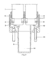
- the base construction shown in FIGS. 1 a and 2 in different views shows a U-shaped discharge vessel 1 with the two ends melted in the form of a pinch 2.
- the bruises 2 are each provided with a groove 3 on the edge and on both sides.
- the melting tip of a pump tube is designated by 4.
- the ends of the discharge vessel 1 open into a base which has a base part 5 corresponding to a socket and a base cap 6.
- a clamp part 7 (for example Pocan) is arranged between these two parts and is provided with struts 8 on both sides facing the bruises 2 of the discharge vessel 1. These struts 8 point obliquely downwards in the direction of the base part 5 and are engaged in the grooves 3 of each pinch 2.
- An elastic clamping part 9 (for example siloprene) is squeezed between the clamp part 7 and the base cap 6, which tightly surrounds the ends of the discharge vessel 1 in the form of an eight and is pressed against it.
- the base part 5 is further below each end of the discharge vessel 1 with one Provide height stop 12, whereby its position is precisely determined.
- FIG. 1b the same parts are provided with the same numbering.
- the only difference from FIG. 1 a is that the pinch 2 of the discharge vessel 1 is provided with elevations 3 'at its end and on both sides.
- the resilient struts 8 are directly behind the elevations 3 'and the diluted pinch 2. This achieves the same advantageous clamping effect as in the exemplary embodiment in FIG. 1a.
- FIG. 1 An example of the type of connection between the base part 5 and the base cap 6 is shown in FIG.
- a groove 10 is incorporated into the base part 5.
- the base cap 6 has a nose 11 at the corresponding point, which snaps into the fillet 10.
- Both parts are made of plastic (e.g. Pocan) by injection molding.
- the electrical connection pins 13 (FIG. 2) of the base are fastened to the base part (5).
- Space for a starter (not shown) is provided within the cavity 14.
- the cams 15 (FIG. 1) serve for fastening the base lamp in a socket.
Landscapes
- Common Detailed Techniques For Electron Tubes Or Discharge Tubes (AREA)
- Fastening Of Light Sources Or Lamp Holders (AREA)
- Vessels And Coating Films For Discharge Lamps (AREA)
Abstract
Description
- Die Erfindung betrifft eine einseitig gesockelte Entladungslampe mit einem Entladungsgefäß, dessen in einem Sockel endender und dort befestigter Teil eine oder mehrere Abdichtungen in Form einer Quetschung aufweist, und der Sockel ein Sockelunterteil und eine Sockelkappe enthält.
- Die Befestigung des Sockels an dem Ende des Entladungsgefäßes erfolgt bekannterweise, indem ein Teil des in der Sockelkappe befindlichen Hohlraumes mit einem durch Temperatur aushärtenden Sockelkitt ausgefüllt wird. Die feste, unlösbare Verbindung entsteht somit erst, nachdem eine bestimmte Temperatur über einen bestimmten Zeitraum auf diese zu verbindenden Teile und damit auch auf den Sockelkitt eingewirkt hat. Dieser Vorgang ist in der Herstellung der Lampen wegen der dafür erforderlichen und ständig zu beheizenden Sockelmaschine nicht nur kostenaufwendig, sondern darüber hinaus auch zeitraubend. Die Verwendung von Sockeln, die ganz aus Kunststoff bestehen, ist zudem stark eingeschränkt, da einerseits der Sockelkitt eine bestimmte Mindesttemperatur für das Aushärten benötigt, andererseits jedoch das Kunststoffmaterial ohne deformiert zu werden nur eine bestimmte Maximaltemperatur verträgt.
- Aufgabe der Erfindung ist es, den Sockel einer einseitig gesockelten Entladungslampe derart zu gestalten, daß das zeitaufwendige und kostenintensive Hantieren mit dem Sockelkitt nicht mehr erforderlich ist.
- Die einseitig gesockelte Entladungslampe mit den im Oberbegriff des Hauptanspruchs genannten Merkmalen ist dadurch gekennzeichnet, daß innerhalb des Sockels Elemente angeordnet sind, die mit dem im Sockel endenden Teil des Entladungsgefäßes form- und kraftschlüssig verbunden sind und dieses kittlos in dem Sockel haltern. Die Quetschung des Entladungsgefäßes ist beidseitig und mindestens an einem Teil ihrer Breite mit einer oder mehreren Vertiefungen versehen. Alternativ dazu können die Quetschungen auch beidseitig und mindestens an einem Teil ihrer Breite mit einer oder mehreren Erhebungen versehen sein. Außerdem sind die innerhalb des Sockels angeordneten Elemente als federnde Streben ausgebildet, die in die Vertiefungen in der Quetschung des Entladungsgefäßes einrasten bzw. die hinter den Erhebungen an den Quetschungen anliegen. Die Streben sind nach der Art von Widerhaken schräg nach unten dem Sokkelunterteil zugeneigt. Die Schräge ermöglicht ein besonders leichtes Einführen der Quetschung des Endes eines Entladungsgefäßes. Während des Einführens öffnen sich die Streben etwas und rasten mit ihren gegenüberliegenden Enden in den in der Quetschung angebrachten Vertiefungen bzw. hinter den Erhebungen ein. Ein Herausziehen des Entladungsgefäßes ohne Zerstörung mindestens eines dieser Teile ist jedoch aufgrund der Schrägstellung der Streben nicht mehr möglich, da sich diese mit zunehmender Zugkraft von selbst mehr und mehr schließen.
- Außerdem ist innerhalb des Sockels ein elastisches Klemmteil eingequetscht, das auf Druck das Ende des Entladungsgefäßes eng anliegend umgibt und dieses zusätzlich haltert.
- Die Streben sind vorzugsweise an ein separates Klammerteil angeformt, das in den Sockel eingesetzt ist. Das Klammerteil liegt in einer ersten Ausführungsform auf dem Sockelunterteil auf, während das Klemmteil wiederum auf dem Klammerteil aufliegt. Die den Sockel oben abschließende Sockelkappe liegt mit Druck ihrerseits auf dem Klemmteil und ist mit dem Sockelunterteil verbunden. Auf diese Weise wirkt das auf Druck beanspruchte Klemmteil halternd für das Entladungsgefäß und das Klammerteil. In einer alternativen Ausführungsform ist das Klammerteil mittels einer Rastverbindung mit der Sockelkappe verbunden, die dann wiederum mit dem Sockelunterteil verbunden ist.
- Für die Montage der Lampe ergibt sich der Vorteil, daß ausschließlich mit vorgefertigten Teilen aus Kunststoff gearbeitet werden kann. Nach dem Zusammenbau der Einzelteile ist die Lampe sofort fertig, da die langen Zeiten zum Aufheizen, Aushärten und Abkühlen des Sokkelbereiches bei der Sockelung mit Sockelkitt entfallen. Darüber hinaus wird während des Sockelns gegenüber dem konventionellen Sockelverfahren Heizenergie eingespart. Die Lampe mit der neuartigen Konstruktion wird somit schneller und kostengünstiger hergestellt. Hinsichtlich der Abziehfestigkeit des Sockels, der Stabilität des Entladungsgefäßes innerhalb des Sockels werden die gleichen Werte wie für eine konventionelle Sockelung erreicht. Die elektrische Sicherheit wird durch die Verwendung von Kunststoffteilen erheblich erhöht. Das Grundkonzept der neuartigen Sockelkonstruktion ist auch bei mehrendigen Entladungsgefäßen anwendbar. Des weiteren ist eine vergleichbare Sockelung in abgewandelter Form auch bei unterschiedlichen Sockeltypen möglich. Bei Verwendung von entsprechend großräumigen Sockelgehäusen ist ebenso die Integration eines Starters sowie ggf. eines Vorschaltgerätes möglich.
- Die Erfindung wird nachstehend anhand eines bevorzugten Ausführungsbeispiels erläutert:
- Figur la zeigt eine Ansicht der Sockelkonstruktion
- Figur Ib zeigt eine alternative Ausführungsform einer Sockelkonstruktion
- Figur 2 zeigt eine um 90o gedrehte Ansicht der Sockelkonstruktion aus Figur 1
- Figur 3 zeigt die Verbindung zwischen dem Sockelunterteil und der Sockelkappe
- Die in den Figuren la und 2 in unterschiedlichen Ansichten dargestellte Sockelkonstruktion zeigt ein U-förmig gebogenes Entladungsgefäß 1 mit den in Form einer Quetschung 2 eingeschmolzenen zwei Enden. Die Quetschungen 2 sind jeweils am Rand und auf beiden Seiten mit einer Nut 3 versehen. Mit 4 ist die Abschmelzspitze eines Pumprohres bezeichnet. Die Enden des Entladungsgefäßes 1 münden in einen Sockel, der ein mit einer Fassung korrespondierendes Sockelunterteil 5 und eine Sockelkappe 6 aufweist. Zwischen diesen beiden Teilen ist ein Klammerteil 7 (z.B. Pocan) angeordnet, das an beiden den Quetschungen 2 des Entladungsgefäßes 1 zugewandten Seiten mit Streben 8 versehen ist. Diese Streben 8 weisen schräg nach unten in Richtung Sockelunterteil 5 und sind in die Nuten 3 jeder Quetschung 2 eingerastet. Zwischen dem Klammerteil 7 und der Sockelkappe 6 ist ein elastisches Klemmteil 9 (z.B. Silopren) eingequetscht, das die Enden des Entladungsgefäßes 1 etwa in Form einer Acht eng umgibt und an diese angedrückt ist. Das Sockelunterteil 5 ist weiterhin unterhalb jedes Endes des Entladungsgefäßes 1 mit je einem Höhenanschlag 12 versehen, wodurch dessen Position genau festgelegt ist.
- In der Figur 1b sind gleiche Teile mit gleicher Bezifferung versehen. Der Unterschied zu der Figur la besteht lediglich darin, daß die Quetschung 2 des Entladungsgefäßes 1 an ihrem Ende und auf beiden Seiten mit Erhebungen 3' versehen ist. Die federnden Streben 8 liegen direkt hinter den Erhebungen 3' und an der verdünnt ausgeführten Quetschung 2 an. Hierdurch wird der gleiche vorteilhafte Klemmeffekt wie in dem Ausführungsbeispiel der Figur 1a erreicht.
- Ein Beispiel der Verbindungsart zwischen dem Sockelunterteil 5 und der Sockelkappe 6 ist in Figur 3 dar-, gestellt. In das Sockelunterteil 5 ist eine Hohlkehle 10 eingearbeitet. Die Sockelkappe 6 weist an der entsprechenden Stelle eine Nase 11 auf, die in die Hohlkehle 10 einschnappt. Beide Teile sind aus Kunststoff (z.B. Pocan) im Spritzgußverfahren hergestellt.
- Die elektrischen Anschlußstifte 13 (Figur 2) des Sokkels sind am Sockelunterteil (5) befestigt. Innerhalb des Hohlraums 14 ist Raum für einen Starter (nicht dargestellt) vorgesehen. Die Nocken 15 (Figur 1) dienen für die Befestigung der gesockelten Lampe in einer Fassung.
Claims (10)
Applications Claiming Priority (2)
| Application Number | Priority Date | Filing Date | Title |
|---|---|---|---|
| DE19843410841 DE3410841A1 (de) | 1984-03-23 | 1984-03-23 | Einseitig gesockelte entladungslampe |
| DE3410841 | 1984-03-23 |
Publications (3)
| Publication Number | Publication Date |
|---|---|
| EP0155672A2 true EP0155672A2 (de) | 1985-09-25 |
| EP0155672A3 EP0155672A3 (en) | 1986-12-03 |
| EP0155672B1 EP0155672B1 (de) | 1989-06-07 |
Family
ID=6231477
Family Applications (1)
| Application Number | Title | Priority Date | Filing Date |
|---|---|---|---|
| EP85103176A Expired EP0155672B1 (de) | 1984-03-23 | 1985-03-19 | Einseitig gesockelte Entladungslampe |
Country Status (3)
| Country | Link |
|---|---|
| US (1) | US4672263A (de) |
| EP (1) | EP0155672B1 (de) |
| DE (2) | DE3410841A1 (de) |
Cited By (3)
| Publication number | Priority date | Publication date | Assignee | Title |
|---|---|---|---|---|
| US5039904A (en) * | 1989-09-28 | 1991-08-13 | General Electric Company | Mount for miniature arc lamp |
| EP0618609A1 (de) * | 1993-03-31 | 1994-10-05 | Koninklijke Philips Electronics N.V. | Elektrische Lampe |
| WO2009043799A1 (de) * | 2007-09-27 | 2009-04-09 | Osram Gesellschaft mit beschränkter Haftung | Entladungslampe mit einem gehäuse und einem entladungsgefäss |
Families Citing this family (7)
| Publication number | Priority date | Publication date | Assignee | Title |
|---|---|---|---|---|
| NL8603127A (nl) * | 1986-12-09 | 1988-07-01 | Philips Nv | Lagedrukkwikdampontladingslamp. |
| DE3918172A1 (de) * | 1989-06-03 | 1990-12-13 | Vendel Karl Heinz | Entladungslampe mit stossabsorber |
| GB2253951A (en) * | 1991-03-19 | 1992-09-23 | Chen Ming Hsiung | Light bulb and holder assembly |
| DE4340995A1 (de) * | 1993-12-02 | 1995-06-08 | Heraeus Noblelight Gmbh | Bestrahlungslampe |
| US7014340B2 (en) * | 2003-03-21 | 2006-03-21 | Welch Allyn, Inc. | Illumination assembly having fluid-tight seal |
| DE102006014294A1 (de) * | 2006-03-28 | 2007-10-04 | Patent-Treuhand-Gesellschaft für elektrische Glühlampen mbH | Elektrische Lampe |
| IN2012DE02309A (de) * | 2012-07-25 | 2015-10-16 | Flowil Int Lighting |
Family Cites Families (7)
| Publication number | Priority date | Publication date | Assignee | Title |
|---|---|---|---|---|
| GB236618A (en) * | 1924-04-03 | 1925-07-03 | Percie Vaughan Castell Evans | An improved method of fixing the caps of thermionic valves, electric lamp bulbs and the like |
| DE2814461A1 (de) * | 1978-04-04 | 1979-10-18 | Patra Patent Treuhand | Elektrische lampe |
| DE2836596A1 (de) * | 1978-08-21 | 1980-03-13 | Patra Patent Treuhand | Elektrische lampe |
| NL185114C (nl) * | 1980-06-04 | 1990-01-16 | Philips Nv | Lagedrukkwikdampontladingslamp. |
| DE3112821A1 (de) * | 1981-03-31 | 1982-10-14 | Patent-Treuhand-Gesellschaft für elektrische Glühlampen mbH, 8000 München | Elektrische lampe mit einer als quetschung ausgebildeten gefaesseinschmelzung sowie vorrichtung und verfahren zur herstellung |
| US4463278A (en) * | 1982-05-21 | 1984-07-31 | General Electric Company | Lamp unit having accurately positioned filament |
| JPS63764A (ja) * | 1986-06-20 | 1988-01-05 | Canon Inc | 文書処理装置 |
-
1984
- 1984-03-23 DE DE19843410841 patent/DE3410841A1/de not_active Withdrawn
-
1985
- 1985-03-08 US US06/709,567 patent/US4672263A/en not_active Expired - Fee Related
- 1985-03-19 EP EP85103176A patent/EP0155672B1/de not_active Expired
- 1985-03-19 DE DE8585103176T patent/DE3570947D1/de not_active Expired
Cited By (3)
| Publication number | Priority date | Publication date | Assignee | Title |
|---|---|---|---|---|
| US5039904A (en) * | 1989-09-28 | 1991-08-13 | General Electric Company | Mount for miniature arc lamp |
| EP0618609A1 (de) * | 1993-03-31 | 1994-10-05 | Koninklijke Philips Electronics N.V. | Elektrische Lampe |
| WO2009043799A1 (de) * | 2007-09-27 | 2009-04-09 | Osram Gesellschaft mit beschränkter Haftung | Entladungslampe mit einem gehäuse und einem entladungsgefäss |
Also Published As
| Publication number | Publication date |
|---|---|
| US4672263A (en) | 1987-06-09 |
| DE3410841A1 (de) | 1985-09-26 |
| EP0155672A3 (en) | 1986-12-03 |
| DE3570947D1 (en) | 1989-07-13 |
| EP0155672B1 (de) | 1989-06-07 |
Similar Documents
| Publication | Publication Date | Title |
|---|---|---|
| DE69121255T2 (de) | Verbinder mit Fluiddichtungsmittel | |
| DE2932638A1 (de) | Elektrische lampe mit einem huelsenfoermigen sockel | |
| EP0155672A2 (de) | Einseitig gesockelte Entladungslampe | |
| EP3579358B1 (de) | Sockelanordnung zur aufnahme einer lampe mit quetschfuss | |
| DE8522797U1 (de) | Kittlos gesockelte elektrische Lampe | |
| DE2941011C2 (de) | ||
| DE69728479T2 (de) | Gesockelte elektrische Lampe | |
| DE3805970A1 (de) | Schraubanschlussvorrichtung fuer elektrische draehte und klemmschuhe | |
| DE1908641C3 (de) | Lampe | |
| DE1539586A1 (de) | Schalttafellampe fuer gedruckte Schaltungen | |
| DE3622377C2 (de) | ||
| DE69204211T2 (de) | Isolierende Durchführung für einen Mittelspannung-Leistungskondensator. | |
| DE1901899A1 (de) | Verbindungsklemmengehaeuse | |
| DE8409059U1 (de) | Einseitig gesockelte Entladungslampe | |
| DE1227151B (de) | Elektrischer Kondensator oder aehnliches elektrisches Bauelement mit Anschlussdraehten | |
| EP0061757A2 (de) | Verfahren zur Herstellung einer als Quetschung ausgebildeten Gefässabdichtung für eine elektrische Lampe und Quetschvorrichtung zum Durchführen des Verfahrens | |
| DE3840140C2 (de) | Steckerstift für elektrische Anschlußstecker | |
| DE19913552B4 (de) | Rotationsmäßig betätigbares elektrisches Bauteil mit einem durch einen Gewindeantrieb betätigten Gleitstück | |
| EP1329931B1 (de) | Kompakte Niederdruckentladungslampe | |
| EP0139882A1 (de) | Verbindung zwischen Ankerwicklungsenden und zugeordneten Segmenten eines Kommutators | |
| DE2507367C3 (de) | Anschlußstecker für ein elektrisches Kabel, insbesondere für ein Hochspannungskabel | |
| CH552286A (de) | Elektrische klemme. | |
| DE4003130A1 (de) | Kindersicherung fuer steckdosen | |
| DE1881801U (de) | Unterlagscheiben-sicherung. | |
| DE20304556U1 (de) | Steckverbindung |
Legal Events
| Date | Code | Title | Description |
|---|---|---|---|
| PUAI | Public reference made under article 153(3) epc to a published international application that has entered the european phase |
Free format text: ORIGINAL CODE: 0009012 |
|
| AK | Designated contracting states |
Designated state(s): DE FR GB IT |
|
| PUAL | Search report despatched |
Free format text: ORIGINAL CODE: 0009013 |
|
| AK | Designated contracting states |
Kind code of ref document: A3 Designated state(s): DE FR GB IT |
|
| 17P | Request for examination filed |
Effective date: 19861023 |
|
| 17Q | First examination report despatched |
Effective date: 19880530 |
|
| GRAA | (expected) grant |
Free format text: ORIGINAL CODE: 0009210 |
|
| AK | Designated contracting states |
Kind code of ref document: B1 Designated state(s): DE FR GB IT |
|
| GBT | Gb: translation of ep patent filed (gb section 77(6)(a)/1977) | ||
| REF | Corresponds to: |
Ref document number: 3570947 Country of ref document: DE Date of ref document: 19890713 |
|
| ET | Fr: translation filed | ||
| ITF | It: translation for a ep patent filed | ||
| PLBE | No opposition filed within time limit |
Free format text: ORIGINAL CODE: 0009261 |
|
| STAA | Information on the status of an ep patent application or granted ep patent |
Free format text: STATUS: NO OPPOSITION FILED WITHIN TIME LIMIT |
|
| 26N | No opposition filed | ||
| ITTA | It: last paid annual fee | ||
| PGFP | Annual fee paid to national office [announced via postgrant information from national office to epo] |
Ref country code: GB Payment date: 19940218 Year of fee payment: 10 |
|
| PGFP | Annual fee paid to national office [announced via postgrant information from national office to epo] |
Ref country code: FR Payment date: 19940317 Year of fee payment: 10 |
|
| PGFP | Annual fee paid to national office [announced via postgrant information from national office to epo] |
Ref country code: DE Payment date: 19940519 Year of fee payment: 10 |
|
| PG25 | Lapsed in a contracting state [announced via postgrant information from national office to epo] |
Ref country code: GB Effective date: 19950319 |
|
| GBPC | Gb: european patent ceased through non-payment of renewal fee |
Effective date: 19950319 |
|
| PG25 | Lapsed in a contracting state [announced via postgrant information from national office to epo] |
Ref country code: FR Free format text: LAPSE BECAUSE OF NON-PAYMENT OF DUE FEES Effective date: 19951130 |
|
| PG25 | Lapsed in a contracting state [announced via postgrant information from national office to epo] |
Ref country code: DE Effective date: 19951201 |
|
| REG | Reference to a national code |
Ref country code: FR Ref legal event code: ST |