EP0153575B1 - Verfahren und Vorrichtung zum Prüfen und Aussortieren von Ziegeln - Google Patents
Verfahren und Vorrichtung zum Prüfen und Aussortieren von Ziegeln Download PDFInfo
- Publication number
- EP0153575B1 EP0153575B1 EP19850100451 EP85100451A EP0153575B1 EP 0153575 B1 EP0153575 B1 EP 0153575B1 EP 19850100451 EP19850100451 EP 19850100451 EP 85100451 A EP85100451 A EP 85100451A EP 0153575 B1 EP0153575 B1 EP 0153575B1
- Authority
- EP
- European Patent Office
- Prior art keywords
- checking
- conveyor belt
- measuring device
- pins
- holding part
- Prior art date
- Legal status (The legal status is an assumption and is not a legal conclusion. Google has not performed a legal analysis and makes no representation as to the accuracy of the status listed.)
- Expired
Links
- 238000000034 method Methods 0.000 title claims description 13
- 239000011449 brick Substances 0.000 title description 38
- 239000002699 waste material Substances 0.000 claims description 10
- 230000009471 action Effects 0.000 claims description 5
- 230000008878 coupling Effects 0.000 claims description 4
- 238000010168 coupling process Methods 0.000 claims description 4
- 238000005859 coupling reaction Methods 0.000 claims description 4
- 230000005540 biological transmission Effects 0.000 claims 2
- 238000012360 testing method Methods 0.000 description 37
- 238000000465 moulding Methods 0.000 description 9
- 241001422033 Thestylus Species 0.000 description 6
- 239000012528 membrane Substances 0.000 description 6
- 241000499489 Castor canadensis Species 0.000 description 4
- 235000011779 Menyanthes trifoliata Nutrition 0.000 description 4
- 239000000919 ceramic Substances 0.000 description 4
- 238000010276 construction Methods 0.000 description 4
- 230000032258 transport Effects 0.000 description 3
- 238000005259 measurement Methods 0.000 description 2
- 230000008569 process Effects 0.000 description 2
- 238000003908 quality control method Methods 0.000 description 2
- 238000013519 translation Methods 0.000 description 2
- 241001295925 Gegenes Species 0.000 description 1
- 238000005452 bending Methods 0.000 description 1
- 230000008901 benefit Effects 0.000 description 1
- 238000011161 development Methods 0.000 description 1
- 239000011451 fired brick Substances 0.000 description 1
- 238000004519 manufacturing process Methods 0.000 description 1
- 238000004806 packaging method and process Methods 0.000 description 1
- 238000003825 pressing Methods 0.000 description 1
- 239000000523 sample Substances 0.000 description 1
- 239000007787 solid Substances 0.000 description 1
- 239000004575 stone Substances 0.000 description 1
- 238000010998 test method Methods 0.000 description 1
Images

Classifications
-
- B—PERFORMING OPERATIONS; TRANSPORTING
- B07—SEPARATING SOLIDS FROM SOLIDS; SORTING
- B07C—POSTAL SORTING; SORTING INDIVIDUAL ARTICLES, OR BULK MATERIAL FIT TO BE SORTED PIECE-MEAL, e.g. BY PICKING
- B07C5/00—Sorting according to a characteristic or feature of the articles or material being sorted, e.g. by control effected by devices which detect or measure such characteristic or feature; Sorting by manually actuated devices, e.g. switches
- B07C5/04—Sorting according to size
- B07C5/06—Sorting according to size measured mechanically
-
- B—PERFORMING OPERATIONS; TRANSPORTING
- B07—SEPARATING SOLIDS FROM SOLIDS; SORTING
- B07C—POSTAL SORTING; SORTING INDIVIDUAL ARTICLES, OR BULK MATERIAL FIT TO BE SORTED PIECE-MEAL, e.g. BY PICKING
- B07C5/00—Sorting according to a characteristic or feature of the articles or material being sorted, e.g. by control effected by devices which detect or measure such characteristic or feature; Sorting by manually actuated devices, e.g. switches
- B07C5/36—Sorting apparatus characterised by the means used for distribution
Definitions
- the invention relates to a method and a device for testing and sorting bricks, which are individually fed on a first conveyor belt to a test device provided with stylus pins and connected to a measuring device, each brick being scanned for flatness by the test device. It is common, for example, to burn baked beaver tail bricks with an eye for flatness, i.e. check for deflection or twisting and, if necessary, cut out bricks that deviate too much. Given today's quality requirements of customers and the large production quantities, such sorting by hand is only possible with considerable personnel expenditure, and the sortability over a longer period of time is also physically demanding.
- a device for checking the measurement and shape accuracy, in particular plate-shaped objects is known (DE-OS 24 34 603).
- Two parallel conveyor belts are provided on which these objects are transported.
- the object to be tested is pressed by a support plate against a stationary measuring plate which has styli.
- the measurement is carried out, after which the object, for example a ceramic plate, is given a marking by a marking element, which indicates whether this object meets the requirements or is to be evaluated as waste.
- the state of the art also includes an aggregate for automatically sorting fired bricks (DE-OS 29 07 700).
- This known device has a hanging trolley carrying a test device with a gripping device for bricks, the bricks being able to be placed on different conveyor belts depending on their quality.
- This known construction is also complex due to the greater number of conveyor belts, the test device also being designed as a photocell and light source and accordingly being susceptible to failure in rough operation.
- a method for sorting out less solid and broken ceramic moldings from a conveying stream running continuously on a conveyor belt to a stacking machine is known (DE-AS 1 109 076).
- the moldings are individually subjected to a pressure-bending load during the conveyance on a preferably two-part conveyor track, the moldings which cannot withstand this load and are not broken further on the conveyor belt, but fall out of the conveying stream.
- This known method is therefore only used to check the strength of the ceramic moldings, but not to determine the flatness, i.e. this procedure cannot be used for high quality requirements.
- a removal device for stone and molding presses is known from the prior art, mechanically actuated arms being used which grip the moldings laterally by means of pneumatic overpressure by means of pressing members that bulge toward the molding (DE-PS 1-012-241).
- the pressure members are designed as a membrane, with each membrane having special elastic supports which rest on the moldings. This known device is therefore not used for quality control of ceramic moldings.
- the present invention has for its object to provide a method and an apparatus of the type mentioned, in which a quality control of bricks is possible in a simple, cost-saving and effective manner.
- this object is achieved in a method in that each tile is checked by the measuring device during the movement of a swiveling device carrying the test device from the first conveyor belt to a second conveyor belt and either thrown off as waste or deposited on the second conveyor belt, and wherein the feeler pins of the test device consisting of the holding part and the test part control the holding action of the holding part via the measuring device.
- the device for carrying out the method is based on a first conveyor belt and a test device provided with stylus pins and a test device connected to a measuring device.
- a swivel device and a second conveyor belt are arranged downstream of the first conveyor belt, the swivel device designed as a double rocker carrying the measuring and testing device with the feeler pins and the feeler pins of the testing device consisting of holding part and test part controlling the holding action of the holding part via the measuring device, whereby a waste device is located below the double rocker.
- This is a simply constructed device which ensures that the test procedure takes place during the swiveling movement between the two conveyor belts.
- each individual brick can be held mechanically, hydraulically or pneumatically by the holding part.
- the holding part is designed as a pneumatic suction head, with a suction plate and fixed points.
- the suction plate can be arranged axially movable on a membrane, outside the suction plate three contact pins are provided as fixed points and the test part has at least two axially movable, offset to the fixed points probe pins.
- Each stylus can be connected to a translation device, this translation device being designed, for example, as a three-armed, spring-loaded lever, one lever arm of which controls the optically acting measuring device.
- this lever arm interacting with the measuring device can be adjustable.
- the measuring device can be designed electronically, mechanically, electrotechnically, hydraulically or pneumatically.
- a device for checking and sorting bricks is shown schematically.
- two conveyor belts 1 and 2 are used, a conveyor device 4 being arranged between these two conveyor belts 1 and 2.
- a test device 3 which is arranged on a swivel device 6.
- this swiveling device 6 is designed as a double swing arm with the two swinging arms 7 and 8 and the coupling part 9.
- joints 31 and 32 Between the coupling part 9 and the swing arms 7 and 8 there are joints 31 and 32; the wings 7 and 8 are firmly connected to the ground via joints 33 and 34.
- the test device 3 has contact pins 14 and feeler pins 16, which will be described in more detail later.
- a brick 5 for example a beaver tail brick
- the testing device 3 swivels to the right over the central point to the conveyor belt 2.
- the tile in question is checked for flatness and twisting. If this brick does not meet the quality requirements of the test devices 3, this brick 5 'is thrown off in the central position of the swivel device 6 and passes through guide walls 30 to a removal device 4, for example a conveyor belt, which transports the waste brick away.
- the relevant brick 5 "corresponds to the quality requirements, it is placed in the right position of the swivel device 6 on the conveyor belt 2, separated from the testing device 3 and, for example, transported to the packaging.
- the bricks 5 are thus transported on a belt 1 with the visible surface lying upwards.
- a test head 3 on the coupling part 9 grips the brick, lifts it and moves it in a circular direction.
- the flatness of the tile is measured during this movement. If this flatness lies within predefined tolerances, the brick 5 "is transported to the end point of the circular arc and placed on a conveyor belt 2. If the tolerances are too large, ie if the brick 5 'is twisted or bent, it will be approximately in the middle of the circular arc from of the test device 3 is released and falls onto the removal device 4.
- the testing device consists of three fixed points 14, which are arranged, for example, in a triangle.
- the slight axial movement of the stylus 16 is translated in any ratio and fed to a measuring device.
- test device 3 shows the construction of the test device 3.
- This test device 3 essentially consists of a holding part 10 and a test part 11.
- the holding part 10 has a suction plate 12 and a suction head 13.
- the suction head 13 is fastened to a housing 35 of the holding part 10 via a membrane 15.
- the stylus pins 16 and the contact pins 14 are also arranged on the housing.
- the suction head 13 installed in the testing device 3 functions in such a way that a suction lath 12 is mounted on a membrane 15 so as to be axially movable. If the suction plate 12 is now placed on the brick 5 and air is sucked out through the suction head 13, the brick 5 is first pressed against the suction head 13 and then raised by the resulting negative pressure on the membrane 15 and against the fixed points 14, i.e. the contact pins. After this process, the styli 16 take effect and measure the flatness of the brick.
- FIG. 1 A single stylus is shown in FIG. This is stored in the housing 15 of the test device 3. Above the stylus 16 there is a three-armed lever 18 with the arms 20, 21 and 22, which is rotatably mounted in a pivot point 26. The arm 20 is spring-loaded, the arm 21 is connected to the upper part of the stylus 16, the arm 22 works with a light source 25.
- the measuring device 17 which is designed as a three-armed lever, is in the region of the light beam 25 if the brick to be measured is of good quality, ie If the lever arm 22 projects into this area of the light beam 25, the relevant, high-quality brick is transported over the circular arc to the removal device 2 and is deposited there as a brick 5 ′′.
- a further lever 23 can be attached to the lever arm 22 of the three-armed lever 18 via a pivot point 24.
- the two levers 22 and 23 thus give a tolerance zone T in the upper region; Within this tolerance zone, the flatness of the tile to be tested meets the quality requirements. In this case, it is possible to pivot lever 23 closer or farther about pivot point 24 in the event of changed quality requirements and thus to increase or decrease the tolerance zone T.
- test device 3 throws off a waste brick 5 'when the light beam 25 is interrupted.
- the measuring device 17 can be designed mechanically, electrically, electronically, hydraulically or pneumatically and is in any case able to give the holding part 10 the control command to transport it to the conveyor belt 2 with a good quality brick 5 ′′ or with waste brick 5 'Throw this on the discharge device 4.
- the device according to the invention makes it possible to test bricks of all kinds for their quality in a simple manner without heavy manual work.
Landscapes
- Engineering & Computer Science (AREA)
- Mechanical Engineering (AREA)
- Length Measuring Devices With Unspecified Measuring Means (AREA)
- Investigating Strength Of Materials By Application Of Mechanical Stress (AREA)
- A Measuring Device Byusing Mechanical Method (AREA)
Description
- Die Erfindung bezieht sich auf ein Verfahren und eine Vorrichtung zum Prüfen und Aussortieren von Ziegeln, welche auf einem ersten Förderband einzeln einer mit Taststiften versehenen und mit einer Messvorrichtung verbundenen Prüfvorrichtung zugeführt werden, wobei jeder Ziegel durch die Prüfvorrichtung auf Ebenflächigkeit abgetastet wird. Es ist üblich, beispielsweise gebrannte Biberschwanz-Ziegel mit dem Auge auf Ebenflächigkeit, d.h. auf Durchbiegung oder Verdrehung, zu kontrollieren und, wenn notwendig, Ziegel auszuscheiden, welche zu grosse Abweichungen aufweisen. Bei den heutigen Qualitätsansprüchen der Kunden und den grossen Herstellungsmengen ist eine derartige Sortierung von Hand nur mit erheblichem Personalaufwand möglich, wobei ausserdem die Sortierbarkeit über einen längeren Zeitraum hinweg körperlich sehr anstrengend ist.
- Als Stand der Technik, von dem die vorliegende Erfindung ausgeht, ist eine Vorrichtung zur Kontrolle der Mess- und Formgenauigkeit, insbesondere plattenförmiger Gegenstände bekannt (DE-OS 24 34 603). Hierbei sind zwei parallellaufende Förderbänder vorgesehen, auf denen diese Gegenstände transportiert werden. Durch eine Stützplatte wird der zu prüfende Gegenstand gegen eine stationäre Messplatte, welche Taststifte aufweist, gedrückt. Hierdurch erfolgt die Messung, wonach durch ein Markierungselement der Gegenstand, beispielsweise eine Keramikplatte, eine Markierung erhält, welche anzeigt, ob dieser Gegenstand den Anforderungen entspricht oder als Abfall zu werten ist.
- Nachteilig ist bei dieser bekannten Konstruktion der hohe bauliche Aufwand und der Verfahrensschritt, dass nur eine Markierung der zu prüfenden Gegenstände, nicht jedoch ein automatisches Ausscheiden erfolgt, so dass letztendlich doch über eine Bedienungsperson diese Tätigkeit vorgenommen werden muss.
- Zum Stand der Technik zählt darüberhinaus ein Aggregat zum automatischen Sortieren gebrannter Ziegelsteine (DE-OS 29 07 700). Diese bekannte Vorrichtung weist einen eine Prüfvorrichtung tragenden Hängewagen mit einer Greifvorrichtung für Ziegelsteine auf, wobei die Ziegelsteine in Abhängigkeit ihrer Qualität auf verschiedene Förderbänder abgelegt werden können. Auch diese bekannte Konstruktion ist bauaufwendig infolge der grösseren Anzahl der Abförderbänder, wobei ausserdem die Prüfvorrichtung als Fotozelle und Lichtquelle ausgebildet und dementsprechend im rauhen Betrieb störanfällig ist.
- Weiterhin ist ein Verfahren zum Aussortieren minder fester und gebrochener keramischer Formlinge aus einem auf einem Förderband kontinuierlich laufenden Förderstrom zu einer Stapelsetzmaschine bekannt (DE-AS 1 109 076). Hierbei werden die Formlinge während der Förderung auf einer vorzugsweise zweiteiligen Förderbahn einzeln einer Druck-Biegebelastung ausgesetzt, wobei die dieser Belastung nicht standhaltenden und zerbrochenen Formlinge auf dem Förderband nicht weiterbefördert werden, sondern aus dem Förderstrom fallen. Dieses bekannte Verfahren dient daher nur zur Prüfung der Festigkeit der keramischen Formlinge, nicht jedoch zur Ermittlung der Ebenflächigkeit, d.h. dieses Verfahren ist nicht für hohe Qualitätsansprüche anwendbar.
- Darüberhinaus ist zum Stand der Technik ein Abnahmegerät für Stein- und Formpressen bekannt, wobei mechanisch betätigbare Arme Anwendung finden, welche die Formlinge seitlich durch pneumatischen Überdruck mittels zum Formling hin sich wölbender Andrückglieder erfassen (DE-PS 1-012-241). Hierbei sind die Andrückglieder als Membran ausgebildet, wobei jede Membran besondere elastische Auflagen aufweist, welche sich an die Formlinge anlegen. Dieses bekannte Gerät dient daher nicht zur Qualitätskontrolle von keramischen Formlingen.
- Demgegenüber liegt der vorliegenden Erfindung die Aufgabe zugrunde, ein Verfahren und eine Vorrichtung der eingangs genannten Art zu schaffen, bei welcher auf einfache, kostensparende und effektive Weise eine Qualitätskontrolle von Ziegeln möglich ist.
- Diese Aufgabe wird erfindungsgemäss bei einem Verfahren dadurch gelöst, dass jeder Ziegel während der Bewegung einer die Prüfvorrichtung tragenden Schwenkeinrichtung von dem ersten Förderband zu einem zweiten Förderband über die Taststifte durch die Messvorrichtung geprüft und entweder als Abfall abgeworfen oder auf dem zweiten Förderband abgelegt wird und wobei die Taststifte der aus Halteteil und Prüfteil bestehenden Prüfvorrichtung über die Messvorrichtung die Haltewirkung des Halteteils steuern.
- Es ergibt sich hieraus der Vorteil, dass die schwere manuelle Arbeit beim Prüfen von Ziegeln bezüglich ihrer Ebenflächigkeit entfällt, wobei die Prüfvorrichtung sowohl den Transport als auch den Prüfvorgang übernimmt und entscheidet, ob ein Ziegel als Abfall abzuwerfen oder als Qualitätsprodukt verwendbar ist. Der gesamte Arbeitsablauf erfolgt automatisch, ohne dass eine Bedienungsperson eingreifen muss.
- Die Vorrichtung zur Durchführung des Verfahrens geht von einem ersten Förderband und einer mit Taststiften versehenen sowie einer mit einer Messvorrichtung verbundenen Prüfvorrichtung aus. Hierbei ist dem ersten Förderband erfindungsgemäss eine Schwenkeinrichtung und ein zweites Förderbänd nachgeordnet, wobei die als Doppelschwinge ausgebildete Schwenkeinrichtung die Mess- und Prüfvorrichtung mit den Taststiften trägt und die Taststifte der aus Halteteil und Prüfteil bestehenden Prüfeinrichtung über die Messvorrichtung die Haltewirkung des Halteteils steuern, wobei sich unterhalb der Doppelschwinge eine Abfallvorrichtung befindet. Es handelt sich hierbei um eine einfach aufgebaute Vorrichtung, welche gewährleistet, dass während der Schwenkbewegung zwischen den beiden Förderbändern das Prüfverfahren stattfindet.
- Nach einem weiteren Merkmal der Erfindung kann durch das Halteteil jeder einzelne Ziegel mechanisch, hydraulisch oder pneumatisch gehaltert werden. In konstruktiver Weiterbildung ist es möglich, dass beispielsweise das Halteteil als pneumatischer Saugkopf ausgebildet ist, mit Saugplatte und Festpunkten. Hierbei kann die Saugplatte axial beweglich an einer Membran angeordnet sein, wobei ausserhalb der Saugplatte drei Anlagestifte als Festpunkte vorgesehen sind und das Prüfteil mindestens zwei axial bewegliche, versetzt zu den Festpunkten angeordnete Taststifte aufweist.
- Jeder Taststift kann mit einer Übersetzungseinrichtung verbunden sein, wobei diese Übersetzungseinrichtung beispielsweise als dreiarmiger, federbeaufschlagter Hebel ausgebildet ist, dessen einer Hebelarm die optisch wirkende Messeinrichtung steuert. Um auf die jeweilige Ziegelart gestellte Toleranzzonen erfassen zu können, kann der mit der Messvorrichtung zusammenwirkende Hebelarm verstellbar sein. Die Messvorrichtung kann elektronisch, mechanisch, elektrotechnisch, hydraulisch oder pneumatisch ausgebildet sein.
- Die Erfindung wird nachfolgend anhand eines in der Zeichnung dargestellten Ausführungsbeispiels näher beschrieben. In der Zeichnung zeigen:
- Fig. 1 eine schematische Seitenansicht der erfindungsgemässen Vorrichtung;
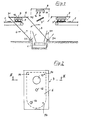
- Fig. 2 eine Draufsicht auf einen Saugkopf nach der Erfindung;
- Fig. 3 einen Schnitt nach der Linie 111-111 in Fig. 2;
- Fig. 4 eine schematische Seitenansicht eines Teils der Prüfvorrichtung.
- In Fig. 1 ist schematisch eine Vorrichtung zum Prüfen und Aussortieren von Ziegeln dargestellt. Hierbei finden zwei Förderbänder 1 und 2 Anwendung, wobei zwischen diesen beiden Förderbändern 1 und 2 eine Abfördervorrichtung 4 angeordnet ist. Zwischen den Förderbändern 1 und 2 befindet sich eine Prüfvorrichtung 3, welche auf einer Schwenkeinrichtung 6 angeordnet ist. Diese Schwenkeinrichtung 6 ist im vorliegenden Fall als Doppelschwinge ausgebildet mit den beiden schwingenden Armen 7 und 8 und dem Koppelteil 9. Zwischen dem Koppelteil 9 und den Schwingen 7 und 8 befinden sich Gelenke 31 und 32; die Schwingen 7 und 8 sind über Gelenke 33 und 34 fest am Boden verbunden.
- Die Prüfvorrichtung 3 besitzt später noch näher beschriebene Anlagestifte 14 sowie Taststifte 16. Wie aus Fig. 1 ersichtlich, wird ein Ziegel 5, beispielsweise ein Biberschwanzziegel, auf dem Förerband 1 in Pfeilrichtung bewegt und bei der linken Stellung der Schwenkeinrichtung 6 von der Prüfeinrichtung 3 erfasst. Nunmehr schwenkt infolge der Bewegung der Doppelschwingen 7 und 8 die Prüfvorrichtung 3 über ihren mittleren Punkt nach rechts zu dem Förderband 2. Während dieser Bewegung erfolgt eine Prüfung des betreffenden Ziegels auf Ebenflächigkeit und auf Verdrehung. Genügt dieser Ziegel den Qualitätsanforderungen der Prüfvorrichtungen 3 nicht, so wird dieser Ziegel 5' in der Mittelstellung der Schwenkeinrichtung 6 abgeworfen und gelangt durch Führungswände 30 auf eine Abfördervorrichtung 4, beispielsweise ein Förderband, welches den Abfallziegel abtransportiert.
- Entspricht der betreffende Ziegel 5" den Qualitätsanforderungen, so wird er in der rechten Lage der Schwenkvorrichtung 6 auf das Förderband 2 abgelegt, von der Prüfeinrichtung 3 getrennt und beispielsweise zur Verpackung abtransportiert.
- Die Ziegel 5 werden also auf einem Band 1 mit der Sichtfläche nach oben liegend antransportiert. Ein Prüfkopf 3 an dem Koppelteil 9 ergreift den Ziegel, hebt ihn an und bewegt ihn in kreisförmiger Richtung. Während dieser Bewegung wird die Ebenflächigkeit des Ziegels gemessen. Liegt diese Ebenflächigkeit innerhalb vorgegebener Toleranzen, wird der Ziegel 5" bis zum Endpunkt des Kreisbogens transportiert und auf einem Abförderband 2 abgelegt. Sind die Toleranzen zu gross, d.h. ist der Ziegel 5' verdreht oder durchgebogen, wird dieser etwa in der Mitte des Kreisbogens von der Prüfvorrichtung 3 gelöst und fällt auf die Abfördervorrichtung 4.
- Die Prüfung der Ziegel 5 auf Ebenflächigkeit geschieht in folgender Weise: Nach Fig. 2 besteht die Prüfvorrichtung aus drei Festpunkten 14, welche beispielsweise im Dreieck angeordnet sind. Zwei bewegliche Taststifte 16, welche beispielsweise beim Biberschwanzziegel in der Mitte sowie an der Ecke eines Rechteckes sitzen, prüfen die Ebenflächigkeit. Dabei wird die geringe axiale Bewegung der Taststifte 16 in einem beliebigen Verhältnis übersetzt und einer Messvorrichtung zugeführt.
- Aus Fig. 3 ist die Konstruktion der Prüfvorrichtung 3 ersichtlich. Diese Prüfvorrichtung 3 besteht im wesentlichen aus einem Halteteil 10 sowie einem Prüfteil 11. Das Halteteil 10 besitzt nach Fig. 3 eine Saugplatte 12 sowie einen Saugkopf 13. Der Saugkopf 13 ist über eine Membran 15 an einem Gehäuse 35 des Halteteils 10 befestigt. An dem Gehäuse sind ebenfalls die Taststifte 16 sowie die Anlagestifte 14 angeordnet.
- Die Halterung und Prüfung des Ziegels 5 wird wie folgt durchgeführt:
- Der am Prüfkopf 2 angebrachte Saugkopf 13, der in dem Moment abhebt, in dem der Ziegel 5 angesaugt wird, drückt diesen mit der Sichtfläche gegen die drei Festpunkte 14, d.h. die Anlagestifte. Diese Anlagestifte, d.h. die Festpunkte 14, sind nach Fig. 2 beispielsweise im Dreieck angeordnet. Zwei bewegliche Taststifte 16, welche beim Biberschwanzziegel z.B. in der Mitte sowie an der Ecke eines Rechtecks angeordnet sind, prüfen die Ebenflächigkeit. Dabei wird die geringe axiale Bewegung der Taststifte 16 in einem beliebigen Verhältnis übersetzt und auf eine Messvorrichtung übertragen.
- Der in der Prüfvorrichtung 3 eingebaute Saugkopf 13 funktioniert in der Weise, dass eine Sauglatte 12 an einer Membran 15 axial beweglich gelagert ist. Wird nun die Saugplatte 12 auf den Ziegel 5 gesetzt, und durch den Saugkopf 13 Luft abgesaugt, so wird zuerst der Ziegel 5 an den Saugkopf 13 gepresst und dann durch den entstehenden Unterdruck auf die Membran 15 angehoben und gegen die Festpunkte 14, d.h. die Anlagestifte, gedrückt. Nach diesem Vorgang treten die Taststifte 16 in Wirkung und messen die Ebenflächigkeit des Ziegels.
- In Fig. 4 ist ein einzelner Taststift dargestellt. Dieser ist in dem Gehäuse 15 der Prüfvorrichtung 3 gelagert. Oberhalb des Taststiftes 16 befindet sich ein in einem Drehpunkt 26 drehbar gelagerter, dreiarmiger Hebel 18 mit den Armen 20, 21 und 22. Der Arm 20 wird hierbei federbeaufschlagt, der Arm 21 steht mit dem oberen Teil des Taststiftes 16 in Verbindung, der Arm 22 arbeitet mit einer Lichtquelle 25 zusammen.
- Befindet sich die als dreiarmiger Hebel ausgebildete Messvorrichtung 17 bei guter Qualität des zu messenden Ziegels im Bereich des Lichtstrahls 25, d.h. ragt der Hebelarm 22 in diesen Bereich des Lichtstrahles 25, so wird der betreffende, qualitativ gute Ziegel über den Kreisbogen zur Abfördervorrichtung 2 transportiert und dort als Ziegel 5" abgelegt.
- Ist jedoch, wie in Fig. 4 dargestellt, ein qualitativ schlechter Ziegel 5" vorhanden, so senkt sich der Taststift 16 bis auf seinen Flansch 40 ab, wodurch der dreiarmige Hebel 18 unte Wirkung der Feder 19 in Uhrzeigerrichtung bewegt und damit aus dem Bereich des Lichtstrahles 25 gelangt. Nunmehr steuert dieser Lichtstrahl eine nicht näher dargestellte Einrichtung, wodurch das Halteteil 10 der Prüfvorrichtung 3 keinen Saugdruck mehr aufweist und der betreffende Abfallziegel 5' damit durch die Führungswände 30 geleitet auf die Abfallvorrichtung 4 abfällt und abtransportiert wird.
- Um den Toleranzbereich T einstellen zu können, kann an dem Hebelarm 22 des dreiarmigen Hebels 18 über einen Drehpunkt 24 ein weiterer Hebel 23 angebracht sein. Die beiden Hebel 22 und 23 geben damit im oberen Bereich eine Toleranzzone T; innerhalb dieser Toleranzzone entspricht die Ebenflächigkeit des zu prüfenden Ziegels den Qualitätsansprüchen. Hierbei ist es möglich, bei geänderten Qualitätsansprüchen den Hebel 23 um den Drehpunkt 24 enger oder weiter zu schwenken und damit die Toleranzzone T zu vergrössern oder zu verkleinern.
- Es ist auch möglich, dass in Umkehr der Konstruktion die Prüfvorrichtung 3 einen Abfallziegel 5' dann abwirft, wenn der Lichtstrahl 25 unterbrochen wird.
- Die Messvorrichtung 17 kann hierbei mechanisch, elektrisch, elektronisch, hydraulisch oder pneumatisch ausgebildet sein und ist in jedem Fall in der Lage, dem Halteteil 10 den Steuerungsbefehl zu geben, bei qualitativ gutem Ziegel 5" diesen zum Förderband 2 zu transportieren bzw. bei Abfallziegel 5' diesen auf die Abfördervorrichtung 4 abzuwerfen.
- Durch die erfindungsgemässe Vorrichtung ist es möglich, auf einfache Weise ohne schwere manuelle Tätigkeit Ziegel aller Art auf ihre Qualität hin zu prüfen.
Claims (9)
Applications Claiming Priority (2)
| Application Number | Priority Date | Filing Date | Title |
|---|---|---|---|
| DE19843404640 DE3404640C2 (de) | 1984-02-09 | 1984-02-09 | Verfahren und Vorrichtung zum Prüfen und Aussortieren von Ziegeln |
| DE3404640 | 1984-02-09 |
Publications (2)
| Publication Number | Publication Date |
|---|---|
| EP0153575A1 EP0153575A1 (de) | 1985-09-04 |
| EP0153575B1 true EP0153575B1 (de) | 1989-01-18 |
Family
ID=6227271
Family Applications (1)
| Application Number | Title | Priority Date | Filing Date |
|---|---|---|---|
| EP19850100451 Expired EP0153575B1 (de) | 1984-02-09 | 1985-01-17 | Verfahren und Vorrichtung zum Prüfen und Aussortieren von Ziegeln |
Country Status (2)
| Country | Link |
|---|---|
| EP (1) | EP0153575B1 (de) |
| DE (1) | DE3404640C2 (de) |
Families Citing this family (10)
| Publication number | Priority date | Publication date | Assignee | Title |
|---|---|---|---|---|
| DE3539549A1 (de) * | 1985-02-13 | 1987-05-14 | Meindl Josef Ohg | Verfahren und vorrichtung zum pruefen und aussortieren von ziegeln |
| DE3504975A1 (de) * | 1985-02-13 | 1986-08-14 | Josef Meindl Beteiligungs-oHG, 8250 Dorfen | Verfahren und vorrichtung zum pruefen und aussortieren von ziegeln |
| DE3515188A1 (de) * | 1985-04-26 | 1986-10-30 | Josef Meindl Beteiligungs-oHG, 8250 Dorfen | Verfahren und vorrichtung zum pruefen und aussortieren von ziegeln |
| ATE59904T1 (de) * | 1985-11-07 | 1991-01-15 | Meindl Josef Ohg | Verfahren und vorrichtung zum pruefen und aussortieren von ziegeln. |
| FR2590811B1 (fr) * | 1985-12-03 | 1989-08-25 | Pont A Mousson | Machine automatique de controle et de tri de pieces, en particulier cylindriques |
| AT1959U1 (de) * | 1997-04-23 | 1998-02-25 | Binder Co Ag | Verfahren zum sortieren von altpapier |
| ES2296526B1 (es) * | 2006-07-21 | 2009-07-14 | Aguila Diawerk, S.L. | Maquina clasificadora de segmentos abrasivos. |
| CN106379726B (zh) * | 2016-11-18 | 2022-10-25 | 山东爱而生智能科技有限公司 | 一种产品分类装置 |
| CN109502309A (zh) * | 2018-12-25 | 2019-03-22 | 菏泽市牡丹区盛鑫源食品有限公司 | 一种蔬菜输送挑选机 |
| CN114377988B (zh) * | 2022-01-20 | 2022-09-06 | 广州大成电子有限公司 | 一种具有智能分拣功能的平贴度检测机 |
Family Cites Families (6)
| Publication number | Priority date | Publication date | Assignee | Title |
|---|---|---|---|---|
| DE274087C (de) * | ||||
| DE1012241B (de) * | 1955-06-03 | 1957-07-11 | Laeis Werke Ag | Abnahmegeraet fuer Stein- und Formpressen |
| DE1109076B (de) * | 1960-05-25 | 1961-06-15 | Kema Keramikmaschinen Goerlitz | Verfahren und Vorrichtung zum Aussortieren keramischer Formlinge aus dem Foerderstrom zu einer Stapelsetzmaschine od. dgl. |
| DE2434603A1 (de) * | 1974-07-18 | 1976-01-29 | Waldmann Geb Sirp Hiltraud | Vorrichtung zur kontrolle der massund formgenauigkeit, insbesondere plattenfoermiger gegenstaende |
| US4146467A (en) * | 1977-11-04 | 1979-03-27 | Jos. Schlitz Brewing Company | Apparatus for detecting and rejecting downed and damaged containers |
| SE7802391L (sv) * | 1978-03-02 | 1979-09-03 | Gustavsberg Ab | Aggregat for automatisk sortering av brent tegel |
-
1984
- 1984-02-09 DE DE19843404640 patent/DE3404640C2/de not_active Expired
-
1985
- 1985-01-17 EP EP19850100451 patent/EP0153575B1/de not_active Expired
Also Published As
| Publication number | Publication date |
|---|---|
| DE3404640A1 (de) | 1985-08-14 |
| DE3404640C2 (de) | 1985-12-05 |
| EP0153575A1 (de) | 1985-09-04 |
Similar Documents
| Publication | Publication Date | Title |
|---|---|---|
| DE3035962C2 (de) | ||
| EP0155380A1 (de) | Bandschleifmaschine | |
| DE2306214C3 (de) | Einrichtung zum Zentrieren der Längsachse eines Rundholzstückes auf eine Bezugsachse | |
| DE2047895C3 (de) | Halte- und Nachführvorrichtung für einen Ultraschall-Fehlerdetektor | |
| DE2937176C2 (de) | ||
| EP0153575A1 (de) | Verfahren und Vorrichtung zum Prüfen und Aussortieren von Ziegeln | |
| DE19527147A1 (de) | Verfahren und Vorrichtung zur Qualitätsprüfung von Formteilen | |
| DE69206747T2 (de) | Vorrichtung zum Messen der Breite der Überlappung einer Klebestelle | |
| DE1473818C3 (de) | Verfahren und Einrichtung zur automatischen Prüfung der Oberflächenkontur und der Dicke gekrümmter oder gebogener Glasscheiben | |
| EP0191156B1 (de) | Vorrichtung zum Prüfen und Aussortieren von Ziegeln | |
| CH626277A5 (en) | Forming press for the production of pressed parts from round stock | |
| DE2434603A1 (de) | Vorrichtung zur kontrolle der massund formgenauigkeit, insbesondere plattenfoermiger gegenstaende | |
| AT393910B (de) | Vorrichtung zur vermessung von rundholz | |
| EP0228515B1 (de) | Verfahren und Vorrichtung zum Prüfen und Aussortieren von Ziegeln | |
| DE2706149C3 (de) | Verfahren zur Ermittlung der wirtschaftlichsten Schnittführung bei Besäumanlagen für Bretter o.dgl | |
| DE3826861A1 (de) | Vorrichtung zum kontinuierlichen ermitteln der masse eines faserbandes mit zwei gegeneinander pressbaren walzen | |
| EP0203387B1 (de) | Verfahren und Vorrichtung zum Prüfen und Aussortieren von Ziegeln | |
| DE2819155C2 (de) | Schneidbank zum Zuschneiden länglicher Metallteile | |
| CH401503A (de) | Vorrichtung zur selbsttätigen Kontrolle von geschlitzten Ringen, insbesondere Kolbenringen | |
| DE3105386A1 (de) | Vorrichtung zum aussondern von gegenstaenden | |
| DE2455997A1 (de) | Teigwickelvorrichtung | |
| DE3539549A1 (de) | Verfahren und vorrichtung zum pruefen und aussortieren von ziegeln | |
| DE3313312C2 (de) | Vorrichtung zur Kontrolle der Verschiebungsneigung eines Bandmessers in einer Spaltmaschine | |
| DE10114812C1 (de) | Abrollstapler | |
| DE3247974C1 (de) | Vorrichtung zum Überprüfen der Flügeligkeit von Dachziegeln |
Legal Events
| Date | Code | Title | Description |
|---|---|---|---|
| PUAI | Public reference made under article 153(3) epc to a published international application that has entered the european phase |
Free format text: ORIGINAL CODE: 0009012 |
|
| AK | Designated contracting states |
Designated state(s): BE FR GB IT LU NL SE |
|
| 17P | Request for examination filed |
Effective date: 19851211 |
|
| 17Q | First examination report despatched |
Effective date: 19870817 |
|
| ITF | It: translation for a ep patent filed | ||
| GRAA | (expected) grant |
Free format text: ORIGINAL CODE: 0009210 |
|
| AK | Designated contracting states |
Kind code of ref document: B1 Designated state(s): BE FR GB IT LU NL SE |
|
| ET | Fr: translation filed | ||
| GBT | Gb: translation of ep patent filed (gb section 77(6)(a)/1977) | ||
| PLBE | No opposition filed within time limit |
Free format text: ORIGINAL CODE: 0009261 |
|
| STAA | Information on the status of an ep patent application or granted ep patent |
Free format text: STATUS: NO OPPOSITION FILED WITHIN TIME LIMIT |
|
| PGFP | Annual fee paid to national office [announced via postgrant information from national office to epo] |
Ref country code: GB Payment date: 19891130 Year of fee payment: 6 |
|
| 26N | No opposition filed | ||
| PGFP | Annual fee paid to national office [announced via postgrant information from national office to epo] |
Ref country code: SE Payment date: 19900116 Year of fee payment: 6 |
|
| PG25 | Lapsed in a contracting state [announced via postgrant information from national office to epo] |
Ref country code: GB Effective date: 19910117 |
|
| PG25 | Lapsed in a contracting state [announced via postgrant information from national office to epo] |
Ref country code: SE Effective date: 19910118 |
|
| ITTA | It: last paid annual fee | ||
| GBPC | Gb: european patent ceased through non-payment of renewal fee | ||
| EPTA | Lu: last paid annual fee | ||
| PGFP | Annual fee paid to national office [announced via postgrant information from national office to epo] |
Ref country code: FR Payment date: 19941215 Year of fee payment: 11 |
|
| PGFP | Annual fee paid to national office [announced via postgrant information from national office to epo] |
Ref country code: BE Payment date: 19941223 Year of fee payment: 11 |
|
| PGFP | Annual fee paid to national office [announced via postgrant information from national office to epo] |
Ref country code: LU Payment date: 19950101 Year of fee payment: 11 |
|
| EUG | Se: european patent has lapsed |
Ref document number: 85100451.5 Effective date: 19910910 |
|
| PGFP | Annual fee paid to national office [announced via postgrant information from national office to epo] |
Ref country code: NL Payment date: 19950131 Year of fee payment: 11 |
|
| PG25 | Lapsed in a contracting state [announced via postgrant information from national office to epo] |
Ref country code: LU Free format text: LAPSE BECAUSE OF NON-PAYMENT OF DUE FEES Effective date: 19960117 |
|
| PG25 | Lapsed in a contracting state [announced via postgrant information from national office to epo] |
Ref country code: BE Effective date: 19960131 |
|
| BERE | Be: lapsed |
Owner name: JOSEF MEINDL BETEILIGUNGS-OHG DORFEN Effective date: 19960131 |
|
| PG25 | Lapsed in a contracting state [announced via postgrant information from national office to epo] |
Ref country code: NL Effective date: 19960801 |
|
| PG25 | Lapsed in a contracting state [announced via postgrant information from national office to epo] |
Ref country code: FR Effective date: 19960930 |
|
| NLV4 | Nl: lapsed or anulled due to non-payment of the annual fee |
Effective date: 19960801 |
|
| REG | Reference to a national code |
Ref country code: FR Ref legal event code: ST |