EP0152015B1 - Vorrichtung zur Verwahrung von Bewehrungsstählen - Google Patents
Vorrichtung zur Verwahrung von Bewehrungsstählen Download PDFInfo
- Publication number
- EP0152015B1 EP0152015B1 EP85100954A EP85100954A EP0152015B1 EP 0152015 B1 EP0152015 B1 EP 0152015B1 EP 85100954 A EP85100954 A EP 85100954A EP 85100954 A EP85100954 A EP 85100954A EP 0152015 B1 EP0152015 B1 EP 0152015B1
- Authority
- EP
- European Patent Office
- Prior art keywords
- reinforcing steel
- steel bars
- openings
- cardboard
- areas
- Prior art date
- Legal status (The legal status is an assumption and is not a legal conclusion. Google has not performed a legal analysis and makes no representation as to the accuracy of the status listed.)
- Expired
Links
Images
Classifications
-
- E—FIXED CONSTRUCTIONS
- E04—BUILDING
- E04G—SCAFFOLDING; FORMS; SHUTTERING; BUILDING IMPLEMENTS OR AIDS, OR THEIR USE; HANDLING BUILDING MATERIALS ON THE SITE; REPAIRING, BREAKING-UP OR OTHER WORK ON EXISTING BUILDINGS
- E04G21/00—Preparing, conveying, or working-up building materials or building elements in situ; Other devices or measures for constructional work
- E04G21/12—Mounting of reinforcing inserts; Prestressing
- E04G21/125—Reinforcement continuity box
Definitions
- the invention relates to a device for storing reinforcing steel for connection areas of concrete structures.
- a disadvantage of the known devices is their comparatively complex structure. This is noticeable in handling and economically.
- the invention has for its object to provide a device for storing reinforcing steel, which is characterized by a particularly simple structure and which is versatile.
- the invention is based on the finding that cardboard, in particular hydrophilic corrugated cardboard, is particularly suitable as a material for devices for storing reinforcing steel.
- the invention relates to a device for storing reinforcing steel for connection areas of concrete structures according to WO-A-8 302128 in the form of an elongated, essentially strip-shaped, one-piece body, which has at least three longitudinal folding edges, can be embedded in the bending-out connection areas of the reinforcing steel are, the anchoring areas protrude from a wide longitudinal surface of the body which has spaced openings in the longitudinal direction.
- the invention is characterized in that the entire body embedding the reinforcing steel consists of hydrophilic cardboard.
- Cardboard is an extremely inexpensive material that can be easily processed.
- the openings can be punched and folded edges can be pre-folded.
- the material is light and easy to transport.
- the hydrophilicity of cardboard has proven to be particularly advantageous for the use of devices for storing reinforcing steel.
- the water of the wet concrete is absorbed by the cardboard and softens it.
- the softened cardboard can then be pulled off particularly easily and removed without any residue. If necessary, the softened cardboard can simply be sprayed away with a water jet.
- corrugated cardboard is particularly suitable because this material has high stiffness but flexibility at the same time. Furthermore, the surface of corrugated cardboard is smooth.
- the reinforcement steels are only held in position by the strip surfaces themselves. It is advantageous if the internal distance between the two wide longitudinal surfaces corresponds approximately to the strength of the reinforcing steel. A slightly larger inner distance is acceptable as long as the reinforcement bars are adequately fixed in their position. With a much larger inner distance than the reinforcing steel thickness, however, the required hold is no longer guaranteed.
- the device can be designed primarily for reinforcement steels of 8 mm thickness. The inner distance is then about 8 mm, possibly a little less. Reinforcing steels with 6 mm are not optimally held in this device, but the device can be used for this. The irons are given an additional hold by the narrow sides of the device.
- the device is also suitable for iron with a diameter of 10 or 12 mm.
- the flexible cardboard material only bulges out.
- the internal distance can also be smaller than the thickness of the reinforcing steel, since the cardboard material used is flexible and with larger thicknesses, the strip is only bulged.
- the strip generally has 4 folded edges. However, an embodiment with only 3 folded edges, in which case a broad longitudinal surface of the strip would rest on the narrow side of a narrow longitudinal surface, would also be considered.
- the wide longitudinal surface in which the openings are provided is a surface which is not subdivided in the longitudinal direction in the folded state.
- the openings provided in the strip preferably correspond to the strength of the reinforcing steel to be used, but can also be somewhat smaller, if appropriate also somewhat larger, because of the easy deformability of cardboard.
- Two rows of openings are preferably provided in the strip, it then being advantageous to make the distances between the individual openings different.
- the distances can be 20 cm in one row and 15 cm in the other row.
- the row with shorter intervals is loaded when a lot of iron is required. Both rows can also be equipped.
- a penetration of concrete into the free openings is not to be feared since the side provided with the openings Device is attached to the formwork.
- a major advantage of the device is that, if desired, any number of further openings can be made in a very simple manner, such as by simply pushing them through, so that all special conditions can be taken into account.
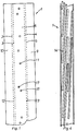
- the strip 1 shown in FIG. 1 consists of cardboard, openings 11 being spaced apart being punched in a wide longitudinal surface 6. Two rows of openings 17, 18 are provided, the distances between the openings in the rows being different.
- the fold edges 2, 3, 4, 5, which are preferably prefolded, run in the longitudinal direction.
- the lateral strip sections 9, 10 preferably have dimensions such that they overlap when folded. But they can also be designed so that they only or not even meet.
- the dimensions of the strip in the longitudinal direction are arbitrary per se. A length of about 130 cm has proven to be suitable.
- the width of the wide longitudinal surfaces is essentially determined by the amount of reinforcing steel embedded in the device and is preferably 6 cm.
- the width of the narrow longitudinal surfaces 12, 13 is measured by the desired internal distance, which should preferably correspond to the thickness of the reinforcing steel 8.
- the openings 11 also preferably correspond to the strength of the reinforcing steels 8. Their spacing and their arrangement are determined by the desired reinforcement.
- the reinforcement steel used generally has a diameter between 6 and 12 mm. Steels with 8 and 10 mm are preferred.
- connection areas 14 of the reinforcing steel 8 are embedded in the device, while the anchoring areas 15 of the reinforcing steel 8 are guided through the openings 11 and protrude.
- the length of the connection areas 14 is usually 30 to 60 cm, often 45 cm.
- the shape of the anchoring areas can be any.
- the length of the anchoring parts 15 is usually 5 to 20 cm.
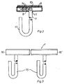
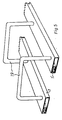
- the anchoring part is designed as a bracket 19.
- the connection areas can be accommodated together in one device.
- the device is preferably closed by gluing. Sealing with adhesive strips has proven to be particularly simple and suitable.
- FIG. 3 shows a side view of the device in the folded state.
- the anchoring areas 15 of the reinforcing steels 8 protrude from the folded strip 1.
- connection areas 14 of the reinforcing steels 8 shows a possible arrangement of the connection areas 14 of the reinforcing steels 8.
- the arrangement is in itself arbitrary and depends on the number and length of the reinforcing steel.
- the device according to the invention is used in a manner known per se, for which reference can be made, for example, to the explanations in European Patent 0 024 697.
Landscapes
- Engineering & Computer Science (AREA)
- Architecture (AREA)
- Mechanical Engineering (AREA)
- Civil Engineering (AREA)
- Structural Engineering (AREA)
- Forms Removed On Construction Sites Or Auxiliary Members Thereof (AREA)
- Spinning Or Twisting Of Yarns (AREA)
- Liquid Developers In Electrophotography (AREA)
- Measuring Pulse, Heart Rate, Blood Pressure Or Blood Flow (AREA)
- Discharge Heating (AREA)
- Heat Treatment Of Strip Materials And Filament Materials (AREA)
Description
- Die Erfindung betrifft eine Vorrichtung zum Verwahren von Bewehrungsstählen für Verbindungsbereiche von Betonbauwerken.
- Es sind zahlreiche Vorrichtungen zum Verwahren von Bewehrungsstählen bekannt und haben sich in der Praxis bewährt.
- Nachteilig an den bekannten Vorrichtungen ist jedoch ihr vergleichsweise aufwendiger Aufbau. Dies macht sich bei der Handhabung und in wirtschaftlicher Hinsicht nachteilig bemerkbar.
- Augrund der komplizierten Aufbaus werden die bekannten Vorrichtungen industriell gefertigt und werden von den Abnehmern als komplette Einheiten bezogen. Da für verschiedene Anwendungen unterschiedlich ausgestaltete Vorrichtungen zum Einsatz kommen, und zwar sowohl im Hinblick auf die Stärke der Bewehrungsstähle als auch deren Formgebung, sind kurzfristige Bestellungen beim Lieferanten oder eine aufwendige Lagerhaltung nicht zu umgehen.
- Der Erfindung liegt die Aufgabe zugrunde, eine Vorrichtung zum Verwahren von Bewehrungsstählen zu schaffen, die sich durch einen besonders einfachen Aufbau auszeichnet und die vielseitig anwendbar ist.
- Der Erfindung liegt die Erkenntnis zugrunde, daß sich als Material für Vorrichtungen zum Verwahren von Bewehrungsstählen Pappe, insbesondere hydrophile Wellpappe, besonders eignet.
- Gegenstand der Erfindung ist eine Vorrichtung zum Verwahren von Bewehrungsstählen für Verbindungsbereiche von Betonbauwerken gemäß WO-A-8 302128 in der Form eines langgestreckten, im wesentlichen streifenförmigen, einteiligen Körpers, der zumindest drei in Längsrichtung verlaufende Faltkanten aufweist, in den herausbiegbare Verbindungsbereiche der Bewehrungsstähle einbettbar sind, deren Verankerungsbereiche aus einer breiten Längsfläche des Körpers herausragen, die in Längsrichtung im Abstand angeordnete Öffnungen aufweist. Die Erfindung ist dadurch gekennzeichnet, daß der gesamte die Bewehrungsstähle einbettende Körper aus hydrophiler Pappe besteht.
- Pappe ist ein äußerst kostengünstiges Material, das einfach bearbeitet werden kann. So können die Öffnungen gestanzt werden und Faltkanten vorgefalzt werden. Das Material ist leicht und gut transportfähig.
- Zur Verwendung von Vorrichtungen zum Verwahren von Bewehrungsstählen erweist sich die Hydrophilität von Pappe als besonders vorteilhaft. Das Wasser des feuchten Betons wird von der Pappe aufgesogen und weicht diese auf.
- Die aufgeweichte Pappe kann dann besonders leicht abgezogen und ohne Rest entfernt werden. Gegebenenfalls kann die aufgeweichte Pappe einfach mit einem Wasserstrahl weggespritzt werden.
- Besonders geeignet ist sogenannte Wellpappe, da dieses Material hohe Steifheit, aber gleichzeitig Flexibilität aufweist. Ferner ist die Oberfläche von Wellpappe glatt.
- Bei der erfindungsgemäßen Vorrichtung werden die Bewehrungsstähle lediglich durch die Streifenflächen selbst in ihrer Stellung gehalten. Es ist vorteilhaft, wenn der Innenabstand zwischen den beiden breiten Längsflächen in etwa der Stärke der Bewehrungsstähle entspricht. Ein etwas größerer Innenabstand ist tragbar, solange die Bewehrungsstähle hinreichend in ihrer Lage fixiert werden. Bei einem wesentlich größeren Innenabstand als der Bewehrungsstahlstärke ist jedoch der erforderliche Halt nicht mehr gewährleistet.
- Beispielsweise kann die Vorrichtung in erster Linie für Bewehrungsstähle vom 8 mm Stärke ausgelegt werden. Der Innenabstand beträgt dann etwa 8 mm, gegebenenfalls auch etwas weniger. Bewehrungsstähle mit 6 mm werden in dieser Vorrichtung zwar nicht optimal gehalten, die Vorrichtung ist aber dafür verwendbar. Einen zusätzlichen Halt erfahren die Eisen durch die Schmalseiten der Vorrichtung. Auch für Eisen mit 10 oder 12 mm Durchmesser ist die Vorrichtung noch geeignet. Das flexible Pappmaterial wölbt sich lediglich auf.
- Der Innenabstand kann auch kleiner sein als die Stärke der Bewehrungsstähle, da das verwendete Pappmaterial flexibel ist und bei größeren Stärken lediglich eine Ausbuchtung des Streifens erfolgt.
- Daß bei der erfindungsgemäßen Vorrichtung der Preßdruck zwischen den aus biegsamer Pappe bestehenden Streifenflächen zur Fixierung der Bewehrungsstähle in ihrer Lage ausreicht, führt zu dem bedeutenden Vorteil, daß besonders geformte Halteelemente, wie beispielsweise die in der europäischen Patentschrift 0 024 697 beschriebenen Halteleisten entbehrlich sind. Naturgemäß komplizieren solche Halteleisten den Aufbau und vermindern die vielseitige-Einsetzbarkeit der Vorrichtung.
- Im allgemeinen weist der Streifen 4 Faltkanten auf. Aber auch eine Ausführungsform mit nur 3 Faltkanten, wobei dann eine breite Längsfläche des Streifens auf der Schmalseite einer schmalen Längsfläche aufliegen oder anschlagen würde, käme in Betracht.
- Die breite Längsfläche, in der die Öffnungen vorgesehen werden, ist eine im zusammengefalteten Zustand in Längsrichtung nicht unterteilte Fläche.
- Die im Streifen vorgesehenen Öffnungen entsprechen vorzugsweise der Stärke der zu verwendenden Bewehrungsstähle, können aber auch aufgrund der leichten Verformbarkeit von Pappe etwas kleiner, ggf. aber auch etwas größer sein.
- Vorzugsweise sind in dem Streifen zwei Reihen von Öffnungen vorgesehen, wobei es dann vorteilhaft ist, die Abstände zwischen den einzelnen Öffnungen unterschiedlich zu machen. Beispielsweise können bei einer Reihe die Abstände 20 cm und bei der anderen Reihe 15 cm betragen. Die Reihe mit kürzeren Abständen wird bestückt, wenn viel Eisen erforderlich ist. Es können auch beide Reihen bestückt werden. Ein Eindringen von Beton in die freien Öffnungen ist nicht zu befürchten, da die mit den Öffnungen versehene Seite der Vorrichtung an der Verschalung befestigt wird. Ein wesentlicher Vorteil der Vorrichtung liegt ferner darin, daß gewünschtenfalls an beliebigen Stellen beliebig viele weitere Öffnungen auf ganz einfache Weise, wie simples Durchstecken, gemacht werden können, so daß allen Sonderbedingungen Rechnung getragen werden kann.
- Im folgenden werden bevorzugte Ausführungsbeispiele der Erfindung anhand der Zeichnung näher erläutert. Es zeigen:
- Fig. 1 die Vorrichtung gemäß der Erfindung im nicht gefalteten Zustand in Draufsicht,
- Fig. 2 die Vorrichtung im zusammengefalteten Zustand mit eingelegten Bewehrungsstählen im Querschnitt,
- Fig. 3 die Vorrichtung im zusammengefalteten Zustand mit eingelegten Bewehrungsstählen in Seitenansicht,
- Fig. 4 die Vorrichtung im Querschnitt in Längsrichtung und
- Fig. 5 eine alternative Ausführungsform der Vorrichtung in perspektivischer Ansicht, teilweise im Schnitt.
- Der in Fig. 1 gezeigte Streifen 1 besteht aus Pappe, wobei in einer breiten Längsfläche 6 im Abstand angeordnete Öffnungen 11 eingestanzt sind. Es sind zwei Reihen von Öffnungen 17, 18, vorgesehen, wobei die Abstände zwischen den Öffnungen in den Reihen unterschiedlich sind.
- In Längsrichtung verlaufen die Faltkanten 2, 3, 4, 5, die vorzugsweise vorgefaltet sind.
- Die seitlichen Streifenabschnitte 9, 10, haben vorzugsweise solche Abmessungen, daß sie sich im zusammengefalteten Zustand überlappen. Sie können aber auch so ausgebildet sein, daß sie lediglich oder sogar nicht aneinanderstoßen.
- Die Abmessungen des Streifens in Längsrichtung sind an sich beliebig. Eine Länge von etwa 130 cm hat sich als geeignet erwiesen.
- Die Breite der breiten Längsflächen bemißt sich im wesentlichen aufgrund der Menge des in der Vorrichtung eingebetteten Bewehrungsstahles und beträgt vorzugsweise 6 cm.
- Die Breite der schmalen Längsflächen 12, 13 bemißt sich durch den gewünschten Innenabstand, der vorzugsweise der Stärke der Bewehrungsstähle 8 entsprechen soll.
- Auch die Öffnungen 11 entsprechen vorzugsweise der Stärke der Bewehrungsstähle 8. Ihr Abstand und ihre Anordnung werden durch die gewünschte Bewehrung festgelegt.
- Die eingesetzten Bewehrungsstähle haben im allgemeinen Durchmesser zwischen 6 und 12 mm. Stähle mit 8 und solche mit 10 mm werden bevorzugt.
- In Fig. 2 ist die Vorrichtung im zusammengefalteten Zustand gezeigt. Die Verbindungsbereiche 14 der Bewehrungsstähle 8 sind in der Vorrichtung eingebettet, während die Verankerungsbereiche 15 der Bewehrungsstähle 8 durch die Öffnungen 11 geführt sind und herausragen. Die Länge der Verbindungsbereiche 14 beträgt üblicherweise 30 bis 60 cm, häufig 45 cm.
- Die Formgebung der Verankerungsbereiche kann beliebig sein. Die Länge der Verankerungsteile 15 beträgt üblicherweise 5 bis 20 cm.
- Es kommt auch in Betracht, daß der Verankerungsteil als Bügel 19 ausgebildet ist. In diesem Fall wird es bevorzugt, die Verbindungsbereiche jeweils in zwei getrennt parallel angeordnete, erfindungsgemäße Vorrichtungen 1,1' einzubetten. Diese Ausführungsform ist in Fig. 5 gezeigt. Alternativ können die Verbindungsbereiche gemeinsam in einer Vorrichtung untergebracht werden.
- Vorzugsweise wird die Vorrichtung durch Verkleben verschlossen. Das Verschließen mit Klebestreifen hat sich als besonders einfach und geeignet erwiesen.
- Mit Klebestreifen oder auf beliebige andere Art und Weise können auch die Endöffnungen 16, 16' verschlossen werden, um das Eindringen von Beton in den Innenraum zu verhindern.
- In Fig. 3 ist eine Seitenansicht der Vorrichtung im zusammengefalteten Zustand gezeigt. Die Verankerungsbereiche 15 der Bewehrungsstähle 8 ragen aus dem zusammengefalteten Streifen 1 heraus.
- In Fig. 4 ist eine mögliche Anordnung der Verbindungsbereiche 14 der Bewehrungsstähle 8 gezeigt. Die Anordnung ist an sich beliebig und richtet sich nach Anzahl und Länge der Bewehrungsstähle. Die Anwendung der erfindungsgemäßen Vorrichtung erfolgt in an sich bekannter Weise, wozu beispielsweise auf die Ausführungen in der europäischen Patentschrift 0 024 697 verwiesen werden kann.
- Von besonderem Vorteil ist bei der vorliegenden Vorrichtung jedoch, daß diese, sei es im Bauhof, bei der Eisenbiegerei oder direkt an der Baustelle mit gewünschten Bewehrungen versehen werden kann.
- Dies gewährleistet sehr weitgehende individuelle Anwendungsmöglichkeiten.
Claims (4)
Priority Applications (1)
| Application Number | Priority Date | Filing Date | Title |
|---|---|---|---|
| AT85100954T ATE48867T1 (de) | 1984-02-10 | 1985-01-30 | Vorrichtung zur verwahrung von bewehrungsstaehlen. |
Applications Claiming Priority (2)
| Application Number | Priority Date | Filing Date | Title |
|---|---|---|---|
| DE3404837 | 1984-02-10 | ||
| DE3404837A DE3404837C2 (de) | 1984-02-10 | 1984-02-10 | Vorrichtung zur Verwahrung von Bewehrungsstählen |
Publications (3)
| Publication Number | Publication Date |
|---|---|
| EP0152015A2 EP0152015A2 (de) | 1985-08-21 |
| EP0152015A3 EP0152015A3 (en) | 1986-08-27 |
| EP0152015B1 true EP0152015B1 (de) | 1989-12-20 |
Family
ID=6227405
Family Applications (1)
| Application Number | Title | Priority Date | Filing Date |
|---|---|---|---|
| EP85100954A Expired EP0152015B1 (de) | 1984-02-10 | 1985-01-30 | Vorrichtung zur Verwahrung von Bewehrungsstählen |
Country Status (4)
| Country | Link |
|---|---|
| EP (1) | EP0152015B1 (de) |
| AT (2) | AT390102B (de) |
| DE (2) | DE3404837C2 (de) |
| FI (1) | FI850544L (de) |
Cited By (3)
| Publication number | Priority date | Publication date | Assignee | Title |
|---|---|---|---|---|
| EP0457315A1 (de) * | 1990-05-17 | 1991-11-21 | Max Frank GmbH & Co. KG | Bewehrungsanschluss sowie Betonkonstruktion mit wenigstens einem Bewehrungsanschluss |
| FR2694954A1 (fr) * | 1992-08-18 | 1994-02-25 | Mure Ets | Caisson pour la mise en attente d'armatures de liaison entre deux parties d'ouvrage en béton contigues et coulées l'une après l'autre. |
| AU2009238356B2 (en) * | 2008-11-21 | 2016-08-18 | Illinois Tool Works Inc. | A Box for Form Work |
Families Citing this family (1)
| Publication number | Priority date | Publication date | Assignee | Title |
|---|---|---|---|---|
| FR2796095B1 (fr) | 1999-07-08 | 2001-09-07 | Cogito | Caisson de boite d'attente et boite d'attente integrant un tel caisson |
Family Cites Families (13)
| Publication number | Priority date | Publication date | Assignee | Title |
|---|---|---|---|---|
| FR1227400A (fr) * | 1959-03-05 | 1960-08-19 | Dispositif assurant la liaison entre des éléments de construction | |
| CH627811A5 (de) * | 1978-12-18 | 1982-01-29 | Brechbuehler Fritz | Armierungseisenhalter zur verwendung bei anschlussbetonierungen. |
| CH637178A5 (en) * | 1979-04-09 | 1983-07-15 | Fritz Brechbuehler | Anchoring device for attaching to a shuttering of a prefabricated concrete unit |
| CH626676A5 (de) * | 1979-05-01 | 1981-11-30 | Witschi H | |
| DE7924049U1 (de) * | 1979-08-23 | 1979-11-22 | Sigma Bauelemente Gmbh | Vorrichtung zum Verwahren von Bewehrungsstaehlen |
| CH641518A5 (en) * | 1979-10-15 | 1984-02-29 | Hp System Ag | Process for producing an anchoring used as a reinforced-concrete connection |
| DE8101897U1 (de) * | 1981-01-27 | 1982-06-16 | Sigma Bauelemente Gmbh, 4800 Bielefeld | "vorrichtung zum verwahren von bewehrungsstaehlen" |
| DE3134253A1 (de) * | 1981-08-29 | 1983-03-10 | Reent 4970 Bad Oeynhausen Obernolte | "vorrichtung zum verwahren von bewehrungsstaehlen" |
| DE8131746U1 (de) * | 1981-10-30 | 1982-03-11 | Max Frank Gmbh & Co Kg, 8441 Leiblfing | Vorrichtung zum verwahren und halten von verbindungsstaehlen fuer betonbauteile |
| FI62888C (fi) * | 1981-12-15 | 1983-03-10 | Rake Oy | Foertillverkat betongarmeringselement och foerfarande vid tillverkning av armeringsanslutningar |
| DE3211563C2 (de) * | 1982-02-25 | 1985-03-28 | Bernd 6451 Mainhausen Reichelt | Schalungs- und Verwahrungselement |
| DE8205197U1 (de) * | 1982-02-25 | 1982-06-16 | Dausend, Hans Werner, 5600 Wuppertal | Verwahrgehaeuse fuer wandanschluss-bewehrungsstaehle |
| AT376267B (de) * | 1982-12-13 | 1984-10-25 | Avi Alpenlaendische Vered | Verbindungsteil fuer zwei stahlbetonbauelemente |
-
1984
- 1984-02-10 DE DE3404837A patent/DE3404837C2/de not_active Expired
- 1984-04-20 AT AT0133984A patent/AT390102B/de not_active IP Right Cessation
-
1985
- 1985-01-30 DE DE8585100954T patent/DE3574889D1/de not_active Expired - Lifetime
- 1985-01-30 EP EP85100954A patent/EP0152015B1/de not_active Expired
- 1985-01-30 AT AT85100954T patent/ATE48867T1/de not_active IP Right Cessation
- 1985-02-08 FI FI850544A patent/FI850544L/fi not_active Application Discontinuation
Cited By (5)
| Publication number | Priority date | Publication date | Assignee | Title |
|---|---|---|---|---|
| EP0457315A1 (de) * | 1990-05-17 | 1991-11-21 | Max Frank GmbH & Co. KG | Bewehrungsanschluss sowie Betonkonstruktion mit wenigstens einem Bewehrungsanschluss |
| US5341616A (en) * | 1990-05-17 | 1994-08-30 | Max Frank Gmbh & Co Kg | Concrete insert element and concrete structure having at least one concrete insert element |
| FR2694954A1 (fr) * | 1992-08-18 | 1994-02-25 | Mure Ets | Caisson pour la mise en attente d'armatures de liaison entre deux parties d'ouvrage en béton contigues et coulées l'une après l'autre. |
| AU2009238356B2 (en) * | 2008-11-21 | 2016-08-18 | Illinois Tool Works Inc. | A Box for Form Work |
| AU2009238356C1 (en) * | 2008-11-21 | 2017-01-19 | Illinois Tool Works Inc. | A Box for Form Work |
Also Published As
| Publication number | Publication date |
|---|---|
| DE3574889D1 (de) | 1990-01-25 |
| FI850544A7 (fi) | 1985-08-11 |
| EP0152015A2 (de) | 1985-08-21 |
| FI850544L (fi) | 1985-08-11 |
| DE3404837C2 (de) | 1986-09-25 |
| ATA133984A (de) | 1989-08-15 |
| ATE48867T1 (de) | 1990-01-15 |
| AT390102B (de) | 1990-03-26 |
| FI850544A0 (fi) | 1985-02-08 |
| EP0152015A3 (en) | 1986-08-27 |
| DE3404837A1 (de) | 1985-08-22 |
Similar Documents
| Publication | Publication Date | Title |
|---|---|---|
| EP0274085B1 (de) | Heftklammer aus Kunststoff | |
| DE1750713B2 (de) | Verbindung von Holzbauteilen einer Baukonstruktion mit zwei Krallenplatten | |
| DE2827950C2 (de) | ||
| DE2907656C2 (de) | ||
| DE3238312C1 (de) | Kantenschutzband | |
| DE2708489B2 (de) | Riemenverbinder | |
| EP0152015B1 (de) | Vorrichtung zur Verwahrung von Bewehrungsstählen | |
| DE3127087A1 (de) | "vorrichtung zum verwahren von bewehrungsstaehlen" | |
| DE2923903C2 (de) | ||
| DE2613522B2 (de) | Fur Holzverbindungen bestimmte Krallenplatte | |
| CH676567A5 (de) | ||
| DE2650181B2 (de) | Krallenplatte | |
| DE1534957B1 (de) | Schalungsrost fuer Betonwaende od.dgl. | |
| DE2843457C2 (de) | Wandbekleidung | |
| EP0397293B1 (de) | Befestigungsschiene für Trapezbleche in der Bautechnik | |
| DE202019103391U1 (de) | Spannvorrichtung für eine Eckverschalung | |
| DE29519544U1 (de) | Sollriß-Fugenschiene für Betonbauten | |
| DE9109283U1 (de) | Schalung für den Betonbau sowie Vorrichtung zum Herstellen der Schalung | |
| DE2065276C3 (de) | Längsstrahlende Antenne mit einem Längsträger und darauf angeordneten Antenne nelementen | |
| DE3623361A1 (de) | Webblatt | |
| DE2128553B2 (de) | Anordnung zum Befestigen eines Kupplungsstucks fur Betonschalungen | |
| DE4439878C2 (de) | Auf einen Beton-Armierungsstab aufsteckbarer Abstandhalter | |
| DE1484328C (de) | Mehrschichtiges Bauelement | |
| DE102024121610A1 (de) | Mehrteiliges Schalungselement zum Erstellen einer Arbeitsfuge | |
| DE2457523B1 (de) | Schalungszuganker mit abstandhalter fuer einander gegenueberstehende schalungswaende |
Legal Events
| Date | Code | Title | Description |
|---|---|---|---|
| PUAI | Public reference made under article 153(3) epc to a published international application that has entered the european phase |
Free format text: ORIGINAL CODE: 0009012 |
|
| AK | Designated contracting states |
Designated state(s): AT BE CH DE FR GB IT LI LU NL SE |
|
| PUAL | Search report despatched |
Free format text: ORIGINAL CODE: 0009013 |
|
| AK | Designated contracting states |
Kind code of ref document: A3 Designated state(s): AT BE CH DE FR GB IT LI LU NL SE |
|
| 17P | Request for examination filed |
Effective date: 19870121 |
|
| 17Q | First examination report despatched |
Effective date: 19871207 |
|
| GRAA | (expected) grant |
Free format text: ORIGINAL CODE: 0009210 |
|
| AK | Designated contracting states |
Kind code of ref document: B1 Designated state(s): AT BE CH DE FR GB IT LI LU NL SE |
|
| REF | Corresponds to: |
Ref document number: 48867 Country of ref document: AT Date of ref document: 19900115 Kind code of ref document: T |
|
| GBT | Gb: translation of ep patent filed (gb section 77(6)(a)/1977) | ||
| REF | Corresponds to: |
Ref document number: 3574889 Country of ref document: DE Date of ref document: 19900125 |
|
| ET | Fr: translation filed | ||
| ITF | It: translation for a ep patent filed | ||
| PGFP | Annual fee paid to national office [announced via postgrant information from national office to epo] |
Ref country code: AT Payment date: 19900627 Year of fee payment: 6 |
|
| PG25 | Lapsed in a contracting state [announced via postgrant information from national office to epo] |
Ref country code: DE Effective date: 19901002 |
|
| PLBE | No opposition filed within time limit |
Free format text: ORIGINAL CODE: 0009261 |
|
| STAA | Information on the status of an ep patent application or granted ep patent |
Free format text: STATUS: NO OPPOSITION FILED WITHIN TIME LIMIT |
|
| 26N | No opposition filed | ||
| PG25 | Lapsed in a contracting state [announced via postgrant information from national office to epo] |
Ref country code: AT Effective date: 19910130 |
|
| ITTA | It: last paid annual fee | ||
| EPTA | Lu: last paid annual fee | ||
| EAL | Se: european patent in force in sweden |
Ref document number: 85100954.8 |
|
| PGFP | Annual fee paid to national office [announced via postgrant information from national office to epo] |
Ref country code: GB Payment date: 19970113 Year of fee payment: 13 |
|
| PGFP | Annual fee paid to national office [announced via postgrant information from national office to epo] |
Ref country code: FR Payment date: 19970120 Year of fee payment: 13 |
|
| PGFP | Annual fee paid to national office [announced via postgrant information from national office to epo] |
Ref country code: SE Payment date: 19970123 Year of fee payment: 13 Ref country code: BE Payment date: 19970123 Year of fee payment: 13 |
|
| PGFP | Annual fee paid to national office [announced via postgrant information from national office to epo] |
Ref country code: CH Payment date: 19970128 Year of fee payment: 13 |
|
| PGFP | Annual fee paid to national office [announced via postgrant information from national office to epo] |
Ref country code: NL Payment date: 19970131 Year of fee payment: 13 |
|
| PGFP | Annual fee paid to national office [announced via postgrant information from national office to epo] |
Ref country code: LU Payment date: 19970709 Year of fee payment: 13 |
|
| PG25 | Lapsed in a contracting state [announced via postgrant information from national office to epo] |
Ref country code: LU Free format text: LAPSE BECAUSE OF NON-PAYMENT OF DUE FEES Effective date: 19980130 Ref country code: GB Free format text: LAPSE BECAUSE OF NON-PAYMENT OF DUE FEES Effective date: 19980130 |
|
| PG25 | Lapsed in a contracting state [announced via postgrant information from national office to epo] |
Ref country code: SE Free format text: LAPSE BECAUSE OF NON-PAYMENT OF DUE FEES Effective date: 19980131 Ref country code: LI Free format text: LAPSE BECAUSE OF NON-PAYMENT OF DUE FEES Effective date: 19980131 Ref country code: FR Free format text: THE PATENT HAS BEEN ANNULLED BY A DECISION OF A NATIONAL AUTHORITY Effective date: 19980131 Ref country code: CH Free format text: LAPSE BECAUSE OF NON-PAYMENT OF DUE FEES Effective date: 19980131 Ref country code: BE Free format text: LAPSE BECAUSE OF NON-PAYMENT OF DUE FEES Effective date: 19980131 |
|
| BERE | Be: lapsed |
Owner name: BLASY ROLF Effective date: 19980131 Owner name: FUHS JOSEH Effective date: 19980131 |
|
| PG25 | Lapsed in a contracting state [announced via postgrant information from national office to epo] |
Ref country code: NL Free format text: LAPSE BECAUSE OF NON-PAYMENT OF DUE FEES Effective date: 19980801 |
|
| REG | Reference to a national code |
Ref country code: CH Ref legal event code: PL |
|
| GBPC | Gb: european patent ceased through non-payment of renewal fee |
Effective date: 19980130 |
|
| NLV4 | Nl: lapsed or anulled due to non-payment of the annual fee |
Effective date: 19980801 |
|
| EUG | Se: european patent has lapsed |
Ref document number: 85100954.8 |
|
| REG | Reference to a national code |
Ref country code: FR Ref legal event code: ST |