EP0143984A2 - Système de contrôle de la hauteur d'un véhicule - Google Patents
Système de contrôle de la hauteur d'un véhicule Download PDFInfo
- Publication number
- EP0143984A2 EP0143984A2 EP84112951A EP84112951A EP0143984A2 EP 0143984 A2 EP0143984 A2 EP 0143984A2 EP 84112951 A EP84112951 A EP 84112951A EP 84112951 A EP84112951 A EP 84112951A EP 0143984 A2 EP0143984 A2 EP 0143984A2
- Authority
- EP
- European Patent Office
- Prior art keywords
- adjusters
- vehicle height
- target
- adjuster
- difference
- Prior art date
- Legal status (The legal status is an assumption and is not a legal conclusion. Google has not performed a legal analysis and makes no representation as to the accuracy of the status listed.)
- Granted
Links
- 239000006096 absorbing agent Substances 0.000 description 11
- 230000035939 shock Effects 0.000 description 11
- 238000000034 method Methods 0.000 description 10
- 239000000725 suspension Substances 0.000 description 4
- 238000010276 construction Methods 0.000 description 2
- 230000003247 decreasing effect Effects 0.000 description 2
- 238000010586 diagram Methods 0.000 description 2
- 238000013459 approach Methods 0.000 description 1
- 230000037396 body weight Effects 0.000 description 1
- 230000006835 compression Effects 0.000 description 1
- 238000007906 compression Methods 0.000 description 1
- 238000004590 computer program Methods 0.000 description 1
- 230000008602 contraction Effects 0.000 description 1
- 239000000284 extract Substances 0.000 description 1
- 238000012544 monitoring process Methods 0.000 description 1
Images
Classifications
-
- B—PERFORMING OPERATIONS; TRANSPORTING
- B60—VEHICLES IN GENERAL
- B60G—VEHICLE SUSPENSION ARRANGEMENTS
- B60G17/00—Resilient suspensions having means for adjusting the spring or vibration-damper characteristics, for regulating the distance between a supporting surface and a sprung part of vehicle or for locking suspension during use to meet varying vehicular or surface conditions, e.g. due to speed or load
- B60G17/015—Resilient suspensions having means for adjusting the spring or vibration-damper characteristics, for regulating the distance between a supporting surface and a sprung part of vehicle or for locking suspension during use to meet varying vehicular or surface conditions, e.g. due to speed or load the regulating means comprising electric or electronic elements
- B60G17/016—Resilient suspensions having means for adjusting the spring or vibration-damper characteristics, for regulating the distance between a supporting surface and a sprung part of vehicle or for locking suspension during use to meet varying vehicular or surface conditions, e.g. due to speed or load the regulating means comprising electric or electronic elements characterised by their responsiveness, when the vehicle is travelling, to specific motion, a specific condition, or driver input
-
- B—PERFORMING OPERATIONS; TRANSPORTING
- B60—VEHICLES IN GENERAL
- B60G—VEHICLE SUSPENSION ARRANGEMENTS
- B60G2204/00—Indexing codes related to suspensions per se or to auxiliary parts
- B60G2204/80—Interactive suspensions; arrangement affecting more than one suspension unit
-
- B—PERFORMING OPERATIONS; TRANSPORTING
- B60—VEHICLES IN GENERAL
- B60G—VEHICLE SUSPENSION ARRANGEMENTS
- B60G2400/00—Indexing codes relating to detected, measured or calculated conditions or factors
- B60G2400/25—Stroke; Height; Displacement
- B60G2400/252—Stroke; Height; Displacement vertical
-
- B—PERFORMING OPERATIONS; TRANSPORTING
- B60—VEHICLES IN GENERAL
- B60G—VEHICLE SUSPENSION ARRANGEMENTS
- B60G2400/00—Indexing codes relating to detected, measured or calculated conditions or factors
- B60G2400/50—Pressure
-
- B—PERFORMING OPERATIONS; TRANSPORTING
- B60—VEHICLES IN GENERAL
- B60G—VEHICLE SUSPENSION ARRANGEMENTS
- B60G2401/00—Indexing codes relating to the type of sensors based on the principle of their operation
- B60G2401/14—Photo or light sensitive means, e.g. Infrared
-
- B—PERFORMING OPERATIONS; TRANSPORTING
- B60—VEHICLES IN GENERAL
- B60G—VEHICLE SUSPENSION ARRANGEMENTS
- B60G2500/00—Indexing codes relating to the regulated action or device
- B60G2500/30—Height or ground clearance
-
- B—PERFORMING OPERATIONS; TRANSPORTING
- B60—VEHICLES IN GENERAL
- B60G—VEHICLE SUSPENSION ARRANGEMENTS
- B60G2600/00—Indexing codes relating to particular elements, systems or processes used on suspension systems or suspension control systems
- B60G2600/02—Retarders, delaying means, dead zones, threshold values, cut-off frequency, timer interruption
-
- B—PERFORMING OPERATIONS; TRANSPORTING
- B60—VEHICLES IN GENERAL
- B60G—VEHICLE SUSPENSION ARRANGEMENTS
- B60G2600/00—Indexing codes relating to particular elements, systems or processes used on suspension systems or suspension control systems
- B60G2600/22—Magnetic elements
- B60G2600/26—Electromagnets; Solenoids
Definitions
- the present invention relates to a vehicle body height control system, or more in particular, to a vehicle body height control system with an improved travelling feeling or performance in the process of the vehicle body height adjustment.
- the system of this invention is hereinafter referred to simply as the vehicle height control system.
- the present invention is applicable to a vehicle height control system comprising a vehicle height adjuster for each of the wheels (a-single adjuster may be provided for all of the rear wheels) for controlling the distance between each of the wheels and the vehicle body, that is, the vehicle body height, with each adjuster independently.
- a vehicle height control system has been proposed heretofore, in which, in order to obtain a desired vehicle height in response to the number of passengers, the amount of loads, the travelling conditions and the road surface conditions, a plurality of vehicle height adjusters are employed to control the vehicle height at a target level.
- This variation in the adjusting rate causes an unstable slant of the vehicle body under adjustment and undesirably makes the driver and passengers (hereinafter simply called "the driver) feel uneasy.
- the present invention is intended to obviate the above-mentioned disadvantage of the prior art system.
- the primary object of the present invention is to provide an improved vehicle height control system which gives an improved travelling feeling or performance in the process of the vehicle height adjustment.
- the present invention provides a vehicle height control system wherein, in order for each of the vehicle height adjusters to operate in coordination with the other vehicle height adjusters, the adjusting operation of a vehicle height adjuster operating at a high adjusting rate is intermitted occasionally.
- the present invention provides a vehicle height control system wherein actual positions resulting from the adjustment of a plurality of vehicle height adjusters are fed back to a control means which operates to compensate for variations in the adjusting procedure among the vehicle height adjusters.
- the vehicle height control system of this invention comprises a plurality of vehicle height adjusters adapted to operate in response to a control signal, position signal generator means for generating an actual position signal in accordance with the result of the adjustment of the respective adjusters, setting means for changing the target adjustment positions of the adjusters, and control means for calculating the target difference between the actual position and the target adjustment position of each adjuster in response to signals from the position signal generator means and the setting means and generating and supplying to the adjusters a plurality of control signals for changing the adjusting rate of each of the adjusters in accordance with the difference between a plurality of target differences obtained.
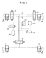
- FIG. 1 An arrangement of the adjusters according to the present invention as applied to a hydropneumatic suspension system is shown in Fig. 1.
- reference numerals 11 to 14 designate shock absorbers, or, in particular, vehicle height adjusting sections thereof.
- the oil pumped up from a reservoir 2l by an electrically-operated hydraulic pump 20 is supplied through a regulation valve 22 to the oil supply passage 15.
- the regulation valve 22 operates in such a manner as to connect the pump 20 to the reservoir 21 when the oil supply pressure is more than a predetermined level.
- the oil supply passage 15 is connected with an accumulator 24 through a normally- closed solenoid valve 23 for preventing the oil supply pressure from pulsating.
- each vehicle height adjuster upon energization of the corresponding one of the solenoid valves 17 to 19 to a position to connect the shock absorbers 11, 12 and 13, 14 with the oil supply passage 15 respectively, oil is supplied into the corresponding one of the vehicle height adjusting cylinders of the shock absorbers 11 to 14, so that the vehicle body height is increased against the vehicle body weight.
- the solenoid valves When the solenoid valves are energized to a position to connect the shock absorbers 11, 12 and 13, 14 to the oil drain passage 16, respectively, on the other hand, oil is drained from the cylinders to decrease the vehicle height.
- the shock absorbers 11 to l4 are provided with vehicle height sensors 25 to 28 for generating an actual position signal indicative of the vehicle height corresponding to the result of the adjustment of the respective vehicle height adjusters.
- vehicle height sensors generate a signal changing stepwise or continuously in accordance with the vehicle height and may be of a well-known photo-electric or inductance type.
- Numeral 29 designates a pressure switch for generating a signal when the pressure in the oil supply passage 15 exceeds a set level, which pressure switch is located at an appropriate position in the oil supply passage 15 and generates a signal for actuating the solenoid valve 23 connected with the accumulator 24.
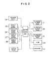
- the setting means designated by numeral 30 generates a change signal for changing the target adjustment position for controlling the vehicle height in relation to at least one of the operating factors corresponding to the number of passengers and the amount of loads, the travelling conditions such as a vehicle speed, the road surface conditions such as an inclination thereof, the operation of a manual switch, etc., as is well known in the art.
- the electric control unit 31 includes an operating circuit (microcomputer) for performing a processing operation in accordance with a predetermined computer program, and an input/output interface for applying the input signal to the operating circuit and transmitting an output signal corresponding to the result of operation of the operating circuit to an external circuit.
- an operating circuit microcomputer
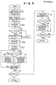
- Fig. 3 shows essential parts of the vehicle height control program used in the present invention which is executed by the operating circuit of the electric control unit 31.
- the program shown in this drawing controls repeated vehicle height adjusting processes.
- the operating circuit of the electric control unit 31 calculates (sets) data A indicative of a target adjustment position for each of the vehicle height adjusters on the basis of the change signal supplied thereto from the setting means 30, whereby target positions A 1 , A 2 and A3 for the respective adjusters are obtained separately which assume predetermined values, respectively, in relation to the change signal.
- the target position A l represents a target value for the front left wheel, A 2 that for the front right wheel, and A3 that for the two rear wheels (an average value).
- the actual position signals generated from the vehicle height sensors 25 to 28 are stored in the operating circuit as data h indicative of actual instantaneous vehicle heights.
- the data h comprise vehicle height data h 1 , h 2 and h 3 including an average value of the vehicle heights on the two rear wheels.
- the vehicle height data h are accumulated at step 103 thereby to calculate data i (i 1 , i 2 , i3) representing the accumulated vehicle heights in a given set time length t l .
- Step 104 determines the set time length t 1 by monitoring timer data T 1 which are periodically reduced to zero by being updated by the counting-up caused by a timer routine not shown.
- step 105 is executed by the operating circuit.
- each of the accumulated vehicle height data i is divided by the set data T 0 corresponding to the set time t 1 thereby to calculate average vehicle height data H (H 1 , H 2 , H 3 ) indicative of the actual position.
- the average vehicle height data H will be called the vehicle height data.
- step 105 clears the accumulated vehicle height data i into zero.
- step 106 differences between the vehicle height data H (actual position) and the target adjustment position A for the respective adjusters, that is, the target differences d (d l , d 2 , d 3 ) are calculated.
- step 107 extracts the maximum value MAX(d) of the target differences thus calculated.
- the operating circuit of the electric control unit 31 performs an initial adjusting operation for each adjuster at steps 108 and 110. Specifically, at step 108, the target difference d of an adjuster is compared with a tolerance a l , and if the target difference d exceeds the tolerance a l , step 109 generates an output signal from the operating circuit for energizing an associated three-position solenoid valve. In the process of execution of step 109, an energizing signal for connecting the shock absorber to the oil supply passage 15 is generated if the target difference d is positive, while an energizing signal for connecting the shock absorber to the oil drain passage 16 is generated if the target difference d is negative. If the target difference d stays within the tolerance a l , on the other hand, no energizing signal for the associated three-position solenoid valve is generated at step 110, thereby de-energizing the same solenoid valve.
- the electric control unit 31 When the electric control unit 31 generates an energizing signal for connecting the shock absorber to the oil supply passage 15 at step 109, the signal from the pressure switch 29 is checked, and if this signal indicates a level higher than a set level, an output signal is generated to energize and open the solenoid valve 23 connected to the accumulator 24, thereby preventing the oil supply pressure from suddenly increasing.
- step 112 checks to decide whether the target difference d for each adjuster is within the tolerance. If all the target differences are within the tolerance, it is decided that the execution of this control program is completed, and the execution of the control program from the step 101 is restarted. In returning to step 101, the energizing signal to the solenoid valve 23 is removed.
- step 112 the process is returned from step 112 to step 101, only when the actual vehicle height H coincides with the target position A within the tolerance a for each adjuster and the actual vehicle height or the target position remains unchanged.
- the secondary adjusting operation is executed based on an instruction from the electric control unit 31 according to the control program shown in steps 113 to 116.
- the adjustment variations for the respective adjusters that is, variations in the adjusting rate
- the adjusting operation of an adjuster of a higher adjusting rate is intermitted temporarily.
- step 113 calculates a difference y between the maximum value MAX(d) of the target differences extracted at step 107 and the target difference d for another adjuster, and step 114 checks to decide whether this difference Y is larger than a predetermined value a 2 .
- the value of the difference Y includes the case where Y ⁇ 0.
- the application of an energizing signal to the associated three-position solenoid valve is stopped in order to stop the adjusting operation (to cancel any possible energized state by step 109) of the adjuster having the target difference d compared at step 115.
- the process Upon execution of the comparing process for the adjuster having a maximum target difference and another adjuster at steps 113 to 115, the process is returned from step 116 to 113, and a similar comparison is made for the other adjuster, and if the target difference d for the adjuster thus compared is smaller than the maximum value MAX(d) by more than the set value a 2 , the adjusting operation of the adjuster thus compared is also stopped.
- the adjusting operation of the particular adjuster is temporarily stopped in accordance with the difference in the target differences of the respective adjusters. Since the electric control unit 31 repeatedly executes the control program from step 101, the program is executed bypassing the step 115 from step 114 when the target difference for the adjuster under continuing adjustment approaches that for the adjuster of which the adjusting operation is intermitted.
- the vehicle height is controlled to a target state without causing any unbalanced vehicle height between adjusters by controlling a three-position solenoid valve in accordance with the variations in the adjusting operations of the adjusters, especially, the adjusting rates thereof.
- This advantage of this system is effectively applied to the adjusting operation of a plurality of vehicle height adjusters, in which the vehicle height on the front wheels is increased or decreased from a certain height, the vehicle height on one of the front or rear wheels is increased while that on the other thereof is decreased, or all the adjusters are raised or lowered.
- the present invention may also be applicable to a vehicle equipped with a vehicle height adjuster using an air suspension, in which case the oil supply/drain system may be replaced by a compression air supply/exhaust system.
- the application of the control program shown in Fig. 3 requires a long set time length t l .
Landscapes
- Engineering & Computer Science (AREA)
- Mechanical Engineering (AREA)
- Vehicle Body Suspensions (AREA)
Applications Claiming Priority (2)
| Application Number | Priority Date | Filing Date | Title |
|---|---|---|---|
| JP202435/83 | 1983-10-27 | ||
| JP58202435A JPS6092914A (ja) | 1983-10-27 | 1983-10-27 | 車高制御装置 |
Publications (3)
| Publication Number | Publication Date |
|---|---|
| EP0143984A2 true EP0143984A2 (fr) | 1985-06-12 |
| EP0143984A3 EP0143984A3 (en) | 1985-12-27 |
| EP0143984B1 EP0143984B1 (fr) | 1989-03-15 |
Family
ID=16457469
Family Applications (1)
| Application Number | Title | Priority Date | Filing Date |
|---|---|---|---|
| EP84112951A Expired EP0143984B1 (fr) | 1983-10-27 | 1984-10-26 | Système de contrôle de la hauteur d'un véhicule |
Country Status (4)
| Country | Link |
|---|---|
| US (1) | US4593920A (fr) |
| EP (1) | EP0143984B1 (fr) |
| JP (1) | JPS6092914A (fr) |
| DE (1) | DE3477169D1 (fr) |
Cited By (10)
| Publication number | Priority date | Publication date | Assignee | Title |
|---|---|---|---|---|
| EP0234552A1 (fr) * | 1986-02-25 | 1987-09-02 | Toyota Jidosha Kabushiki Kaisha | Système de réglage du roulis de la caisse d'un véhicule en détectant et en compensant la position angulaire du volant contraire au sens de rotation du véhicule |
| EP0235695A1 (fr) * | 1986-02-21 | 1987-09-09 | Toyota Jidosha Kabushiki Kaisha | Système de réglage du roulis de la caisse d'un véhicule en détectant et en compensant par des changements rapides de la position angulaire du volant comme pendant la conduite en cas d'urgence |
| EP0217233A3 (en) * | 1985-10-01 | 1988-07-20 | Toyota Jidosha Kabushiki Kaisha | Suspension controller |
| EP0249207A3 (en) * | 1986-06-12 | 1988-11-02 | Gesellschaft Fur Hydraulik-Zubehor Mbh | Level-adjusting device for motor vehicles |
| GB2204286A (en) * | 1987-04-30 | 1988-11-09 | Williams Grand Prix Eng | Active fluid suspension system |
| EP0222329A3 (en) * | 1985-11-07 | 1988-12-14 | Kabushiki Kaisha Toyota Chuo Kenkyusho | Vibration control apparatus |
| EP0297736A3 (en) * | 1987-06-29 | 1989-12-27 | General Motors Corporation | Vehicle air suspension apparatus with accurate side to side levelling |
| GB2223993A (en) * | 1988-10-14 | 1990-04-25 | Fuji Heavy Ind Ltd | Apparatus for adjusting vehicle body height |
| GB2260425A (en) * | 1991-10-09 | 1993-04-14 | Mannesmann Ag | Feedforward position control system |
| EP0393655B1 (fr) * | 1989-04-20 | 1993-06-16 | Nissan Motor Co., Ltd. | Réglage de la hauteur dans un système de suspension actif |
Families Citing this family (31)
| Publication number | Priority date | Publication date | Assignee | Title |
|---|---|---|---|---|
| EP0187370B1 (fr) * | 1984-12-25 | 1989-11-15 | Toyota Jidosha Kabushiki Kaisha | Dispositif de réglage pour suspension arrière |
| JPS61150806A (ja) * | 1984-12-25 | 1986-07-09 | Toyota Motor Corp | サスペンシヨン制御装置 |
| EP0186183B1 (fr) * | 1984-12-25 | 1990-04-25 | Toyota Jidosha Kabushiki Kaisha | Dispositif de réglage pour suspension de roue arrière |
| JPH07115572B2 (ja) * | 1985-01-16 | 1995-12-13 | トヨタ自動車株式会社 | 後輪のサスペンション制御装置 |
| USRE33626E (en) * | 1985-01-16 | 1991-07-02 | Toyota Jidosha Kabushiki Kaisha | Rear suspension controller |
| US4726604A (en) * | 1985-01-28 | 1988-02-23 | Toyota Jidosha Kabushiki Kaisha | Rear suspension controller |
| US4717172A (en) * | 1985-02-04 | 1988-01-05 | Olympus Optical Co., Ltd. | Suspension controller |
| JPS61287808A (ja) * | 1985-06-14 | 1986-12-18 | Nissan Motor Co Ltd | 車両のサスペンシヨン制御装置 |
| JPH0777843B2 (ja) * | 1986-01-31 | 1995-08-23 | 日産自動車株式会社 | 車高制御装置 |
| EP0233522B1 (fr) * | 1986-02-08 | 1990-05-16 | Franz Dr. Tuczek | Réglage du niveau et de l'inclinaison pour un véhicule |
| JPH0737203B2 (ja) * | 1986-05-08 | 1995-04-26 | 日産自動車株式会社 | 車高制御装置 |
| JPS63199809U (fr) * | 1987-06-13 | 1988-12-22 | ||
| DE3867849D1 (de) * | 1988-04-14 | 1992-02-27 | Bosch Gmbh Robert | Kalibrierung eines hoehenregelungssystems fuer ein fahrzeug mit luftfederung. |
| US4902903A (en) * | 1988-10-27 | 1990-02-20 | Segerson Eugene E | Apparatus employing reflective optical means |
| DE3919040A1 (de) * | 1989-06-10 | 1990-12-13 | Porsche Ag | Verfahren und vorrichtung zur justierung einer hoehenstands-regelanlage eines fahrzeugs |
| DE4115593A1 (de) * | 1991-05-14 | 1992-11-19 | Bosch Gmbh Robert | Niveauregeleinrichtung fuer fahrzeuge |
| EP0592536B1 (fr) * | 1991-07-02 | 1999-05-19 | Kinetic Limited | Systeme de suspension de vehicule |
| US5267466A (en) * | 1991-09-26 | 1993-12-07 | Ford Motor Co. | Apparatus and method for calibrating a suspension control module |
| US5915701A (en) * | 1993-12-30 | 1999-06-29 | Kinetic Limited | Vehicle suspension system |
| JP3470573B2 (ja) * | 1997-11-21 | 2003-11-25 | トヨタ自動車株式会社 | 車高調整装置 |
| KR20010034768A (ko) | 1998-04-07 | 2001-04-25 | 피. 데니스 맥닐리 | 서스펜션 및 동적 하중을 보정하는 유체 스프링 |
| DE19949152C2 (de) * | 1999-10-12 | 2003-07-31 | Mowag Motorwagenfabrik Ag Kreu | Hydropneumatische Federung |
| DE10019531C2 (de) * | 2000-04-20 | 2003-08-07 | Zf Sachs Ag | Federungssystem für Kraftfahrzeuge |
| US7192012B2 (en) * | 2003-08-18 | 2007-03-20 | Haldex Brake Corporation | Air suspension system with supply air restriction valve |
| DE202005014926U1 (de) * | 2005-09-21 | 2005-11-24 | Trw Automotive Gmbh | Stabilisator-Baugruppe für ein Kraftfahrzeug |
| WO2007111158A1 (fr) | 2006-03-29 | 2007-10-04 | Kubota Corporation | Chargeur sur roues |
| JP4793577B2 (ja) * | 2006-11-10 | 2011-10-12 | アイシン精機株式会社 | 車高調整装置 |
| DE102007018166A1 (de) * | 2007-04-18 | 2008-10-23 | Dr. Ing. H.C. F. Porsche Aktiengesellschaft | Vorrichtung zum Einstellen einer Raumlage für ein Kraftfahrzeug |
| JP5947320B2 (ja) * | 2014-01-27 | 2016-07-06 | 株式会社ショーワ | 車高調整装置、車高調整方法 |
| US12043321B2 (en) | 2020-08-25 | 2024-07-23 | Agco Corporation | System and method for adjusting the chassis height of a machine |
| CN113879063B (zh) * | 2021-11-18 | 2023-05-09 | 珠海格力电器股份有限公司 | 车辆悬架调节方法、装置、非易失性存储介质及处理器 |
Family Cites Families (7)
| Publication number | Priority date | Publication date | Assignee | Title |
|---|---|---|---|---|
| JPS5239524B2 (fr) * | 1973-04-09 | 1977-10-05 | ||
| GB1456873A (en) * | 1973-06-30 | 1976-12-01 | Nissan Motor | Vehicle having a fluid operated vehicle body level control system |
| JPS5660710A (en) * | 1979-10-19 | 1981-05-25 | Tokico Ltd | Car height adjuster |
| JPS5858243B2 (ja) * | 1980-01-17 | 1983-12-24 | 本田技研工業株式会社 | 車高調整装置の制御回路 |
| GB2071587B (en) * | 1980-03-05 | 1983-11-02 | Lucas Industries Ltd | Vehicle suspension system |
| GB2097344B (en) * | 1981-04-08 | 1984-05-16 | Lucas Ind Plc | Self-leveling suspension system |
| US4483546A (en) * | 1981-04-08 | 1984-11-20 | Lucas Industries Public Limited Company | Self-levelling suspension |
-
1983
- 1983-10-27 JP JP58202435A patent/JPS6092914A/ja active Pending
-
1984
- 1984-10-26 EP EP84112951A patent/EP0143984B1/fr not_active Expired
- 1984-10-26 DE DE8484112951T patent/DE3477169D1/de not_active Expired
- 1984-10-26 US US06/665,065 patent/US4593920A/en not_active Expired - Fee Related
Cited By (15)
| Publication number | Priority date | Publication date | Assignee | Title |
|---|---|---|---|---|
| EP0217233A3 (en) * | 1985-10-01 | 1988-07-20 | Toyota Jidosha Kabushiki Kaisha | Suspension controller |
| EP0222329A3 (en) * | 1985-11-07 | 1988-12-14 | Kabushiki Kaisha Toyota Chuo Kenkyusho | Vibration control apparatus |
| EP0235695A1 (fr) * | 1986-02-21 | 1987-09-09 | Toyota Jidosha Kabushiki Kaisha | Système de réglage du roulis de la caisse d'un véhicule en détectant et en compensant par des changements rapides de la position angulaire du volant comme pendant la conduite en cas d'urgence |
| US4807128A (en) * | 1986-02-21 | 1989-02-21 | Toyota Jidosha Kabushiki Kaisha | System for vehicle body roll control detecting and compensating for rapid rate of change of steering angle as during emergency steering |
| US4803627A (en) * | 1986-02-25 | 1989-02-07 | Toyota Jidosha Kabushiki Kaisha | System for vehicle body roll control detecting and compensating steering oppositely to vehicle turning direction |
| EP0234552A1 (fr) * | 1986-02-25 | 1987-09-02 | Toyota Jidosha Kabushiki Kaisha | Système de réglage du roulis de la caisse d'un véhicule en détectant et en compensant la position angulaire du volant contraire au sens de rotation du véhicule |
| EP0249207A3 (en) * | 1986-06-12 | 1988-11-02 | Gesellschaft Fur Hydraulik-Zubehor Mbh | Level-adjusting device for motor vehicles |
| GB2204286A (en) * | 1987-04-30 | 1988-11-09 | Williams Grand Prix Eng | Active fluid suspension system |
| US4861066A (en) * | 1987-04-30 | 1989-08-29 | Williams Grand Prix Engineering Limited | Vehicle suspension systems |
| GB2204286B (en) * | 1987-04-30 | 1991-02-06 | Williams Grand Prix Eng | Vehicle suspension systems |
| EP0297736A3 (en) * | 1987-06-29 | 1989-12-27 | General Motors Corporation | Vehicle air suspension apparatus with accurate side to side levelling |
| GB2223993A (en) * | 1988-10-14 | 1990-04-25 | Fuji Heavy Ind Ltd | Apparatus for adjusting vehicle body height |
| GB2223993B (en) * | 1988-10-14 | 1992-09-09 | Fuji Heavy Ind Ltd | Apparatus for adjusting vehicle body height |
| EP0393655B1 (fr) * | 1989-04-20 | 1993-06-16 | Nissan Motor Co., Ltd. | Réglage de la hauteur dans un système de suspension actif |
| GB2260425A (en) * | 1991-10-09 | 1993-04-14 | Mannesmann Ag | Feedforward position control system |
Also Published As
| Publication number | Publication date |
|---|---|
| EP0143984B1 (fr) | 1989-03-15 |
| DE3477169D1 (en) | 1989-04-20 |
| US4593920A (en) | 1986-06-10 |
| JPS6092914A (ja) | 1985-05-24 |
| EP0143984A3 (en) | 1985-12-27 |
Similar Documents
| Publication | Publication Date | Title |
|---|---|---|
| EP0143984A2 (fr) | Système de contrôle de la hauteur d'un véhicule | |
| US4787644A (en) | Height control system for automotive vehicle with vehicular profile regulating feature | |
| US4611815A (en) | Vehicle height control system | |
| DE4025309C2 (de) | Aktives Aufhängungssystem für Fahrzeuge mit Steuervorrichtung zur Unterdrückung von Stellungsänderungen des Fahrzeugaufbaus | |
| DE4024305A1 (de) | Aktives aufhaengungssystem fuer kraftfahrzeuge | |
| US4591185A (en) | Vehicle height control system | |
| JPH01122717A (ja) | 能動型サスペンション装置 | |
| EP0419865A1 (fr) | Système de commande de pressions pour une suspension | |
| US5855420A (en) | Electronically controlled brake booster and method of operation thereof | |
| EP0143983B1 (fr) | Système de contrôle de la hauteur d'un véhicule | |
| DE4221059C2 (de) | Verfahren und Vorrichtung zur Steuerung einer Fahrzeugaufhängung | |
| US5251929A (en) | Hydraulic supply arrangement for use with active automotive suspension or the like | |
| GB2312481A (en) | Controlling the brake system of a vehicle | |
| JPH06247126A (ja) | 自動車シャシを閉ループおよび/または開ループ制御するシステム | |
| DE3872530T2 (de) | Hoehenregelungssystem fuer ein fahrzeug mit luftfederung. | |
| US5893041A (en) | Suspension apparatus for changing characteristics of a vehicle suspension by controlling hydraulic cylinders | |
| JPH07186668A (ja) | サスペンションの制御装置 | |
| US5160160A (en) | Active suspension system | |
| JPS61261116A (ja) | 車高制御装置 | |
| JP2506331B2 (ja) | 能動制御型サスペンシヨン装置 | |
| JPS6346910A (ja) | アクテイブサスペンシヨン装置 | |
| JPH078247Y2 (ja) | 車高調整装置 | |
| JPS6261812A (ja) | 車両サスペンシヨン制御装置 | |
| JPH0620805B2 (ja) | 流体圧サスペンシヨン制御装置 | |
| JPH0621764Y2 (ja) | エアサスペンシヨンの制御装置 |
Legal Events
| Date | Code | Title | Description |
|---|---|---|---|
| PUAI | Public reference made under article 153(3) epc to a published international application that has entered the european phase |
Free format text: ORIGINAL CODE: 0009012 |
|
| AK | Designated contracting states |
Designated state(s): DE FR GB |
|
| PUAL | Search report despatched |
Free format text: ORIGINAL CODE: 0009013 |
|
| AK | Designated contracting states |
Designated state(s): DE FR GB |
|
| 17P | Request for examination filed |
Effective date: 19860430 |
|
| 17Q | First examination report despatched |
Effective date: 19870227 |
|
| GRAA | (expected) grant |
Free format text: ORIGINAL CODE: 0009210 |
|
| AK | Designated contracting states |
Kind code of ref document: B1 Designated state(s): DE FR GB |
|
| REF | Corresponds to: |
Ref document number: 3477169 Country of ref document: DE Date of ref document: 19890420 |
|
| ET | Fr: translation filed | ||
| REG | Reference to a national code |
Ref country code: GB Ref legal event code: 746 |
|
| PLBE | No opposition filed within time limit |
Free format text: ORIGINAL CODE: 0009261 |
|
| STAA | Information on the status of an ep patent application or granted ep patent |
Free format text: STATUS: NO OPPOSITION FILED WITHIN TIME LIMIT |
|
| 26N | No opposition filed | ||
| REG | Reference to a national code |
Ref country code: FR Ref legal event code: DL |
|
| PGFP | Annual fee paid to national office [announced via postgrant information from national office to epo] |
Ref country code: FR Payment date: 19911007 Year of fee payment: 8 |
|
| PGFP | Annual fee paid to national office [announced via postgrant information from national office to epo] |
Ref country code: GB Payment date: 19911015 Year of fee payment: 8 |
|
| PGFP | Annual fee paid to national office [announced via postgrant information from national office to epo] |
Ref country code: DE Payment date: 19911129 Year of fee payment: 8 |
|
| PG25 | Lapsed in a contracting state [announced via postgrant information from national office to epo] |
Ref country code: GB Effective date: 19921026 |
|
| GBPC | Gb: european patent ceased through non-payment of renewal fee |
Effective date: 19921026 |
|
| PG25 | Lapsed in a contracting state [announced via postgrant information from national office to epo] |
Ref country code: FR Effective date: 19930630 |
|
| PG25 | Lapsed in a contracting state [announced via postgrant information from national office to epo] |
Ref country code: DE Effective date: 19930701 |
|
| REG | Reference to a national code |
Ref country code: FR Ref legal event code: ST |