EP0142745B1 - Vorrichtung zum Abwickeln von in Schuppenformation aufgewickelten Druckprodukten - Google Patents
Vorrichtung zum Abwickeln von in Schuppenformation aufgewickelten Druckprodukten Download PDFInfo
- Publication number
- EP0142745B1 EP0142745B1 EP84113008A EP84113008A EP0142745B1 EP 0142745 B1 EP0142745 B1 EP 0142745B1 EP 84113008 A EP84113008 A EP 84113008A EP 84113008 A EP84113008 A EP 84113008A EP 0142745 B1 EP0142745 B1 EP 0142745B1
- Authority
- EP
- European Patent Office
- Prior art keywords
- conveyor
- winding
- roll
- frame
- roller
- Prior art date
- Legal status (The legal status is an assumption and is not a legal conclusion. Google has not performed a legal analysis and makes no representation as to the accuracy of the status listed.)
- Expired
Links
Images

Classifications
-
- B—PERFORMING OPERATIONS; TRANSPORTING
- B65—CONVEYING; PACKING; STORING; HANDLING THIN OR FILAMENTARY MATERIAL
- B65H—HANDLING THIN OR FILAMENTARY MATERIAL, e.g. SHEETS, WEBS, CABLES
- B65H5/00—Feeding articles separated from piles; Feeding articles to machines
- B65H5/28—Feeding articles stored in rolled or folded bands
-
- B—PERFORMING OPERATIONS; TRANSPORTING
- B65—CONVEYING; PACKING; STORING; HANDLING THIN OR FILAMENTARY MATERIAL
- B65H—HANDLING THIN OR FILAMENTARY MATERIAL, e.g. SHEETS, WEBS, CABLES
- B65H2301/00—Handling processes for sheets or webs
- B65H2301/40—Type of handling process
- B65H2301/41—Winding, unwinding
- B65H2301/419—Winding, unwinding from or to storage, i.e. the storage integrating winding or unwinding means
- B65H2301/4192—Winding, unwinding from or to storage, i.e. the storage integrating winding or unwinding means for handling articles of limited length in shingled formation
- B65H2301/41922—Winding, unwinding from or to storage, i.e. the storage integrating winding or unwinding means for handling articles of limited length in shingled formation and wound together with single belt like members
-
- B—PERFORMING OPERATIONS; TRANSPORTING
- B65—CONVEYING; PACKING; STORING; HANDLING THIN OR FILAMENTARY MATERIAL
- B65H—HANDLING THIN OR FILAMENTARY MATERIAL, e.g. SHEETS, WEBS, CABLES
- B65H2701/00—Handled material; Storage means
- B65H2701/10—Handled articles or webs
- B65H2701/19—Specific article or web
- B65H2701/1932—Signatures, folded printed matter, newspapers or parts thereof and books
Definitions
- the present invention relates to a device for unwinding printed products wound together with a winding tape in a scale formation on a winding core according to the preamble of claim 1.
- the continuous conveyor which is designed as a belt conveyor pivotably mounted at the head end, serves as a support for the winding tape and with it coiled up printed products.
- the belt conveyor runs below the scale formation.
- the winding belt separates from the printed product scale stream at the head end of the belt conveyor and is wound onto a belt reel on the side of the belt conveyor opposite the winding.
- the angle of attack of the belt conveyor changes as the winding diameter becomes smaller. It must be avoided that the angle of inclination of the belt conveyor becomes too large, otherwise there is a risk of the printed products slipping. This danger can be countered by using a belt conveyor with a long conveying path, in which the distance between its pivot point and the winding is chosen to be relatively large.
- such an embodiment has the disadvantage of a correspondingly large overall length.
- the conveyor path defined by the belt conveyor cannot easily be given a course that deviates significantly from a straight line.
- the present invention is based on the object of creating a device of the type mentioned at the outset which enables the unwound printed products to be carried away correctly and which, with the simplest possible and space-saving construction, leaves great freedom in the structural design.
- this deflection point is selected adjacent to the detachment point of the printed products from the roll, then the unwound printed products can be turned and removed along a relatively short conveying path, which allows a space-saving design.
- This advantage of a short overall length is particularly significant if the detaching point is arranged on the underside of the winding and the head end of the continuous conveyor is arranged as close as possible to the circumference of the full winding.
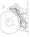
- the unwinding device has a frame 1 which is provided with bearings (not shown) for receiving a winding core 2. These bearings are designed in such a way that the winding cores 2 can be easily inserted into and removed from the bearings.
- the winding core 2 is freely rotatable about its axis 2a.
- the winding core 2 carries a winding 3, the winding layers of which are formed by printed products 4 arranged in a scale formation S.
- the individual winding layers are separated from one another in a known manner by a winding tape 5 under tension. This winding tape 5 runs in each case on that side of the scale formation S which is in the winding Winding core 2 is turned away.
- the winding tape 5 is guided behind the detachment point 6, at which the winding tape 5 and also the printed products 4 run off the roll 3 during unwinding, over a deflection roller 7 and over guide rollers 8 and 9.
- Both the deflection roller 7 and the guide rollers 8 and 9 are mounted on a frame 10 which is mounted on the frame 1 so as to be pivotable about an axis 10a.
- the pivot axis 10a of the frame 10 runs parallel to the axis of rotation 2a of the winding core 2.
- the winding tape 5 runs over a conveyor roller 11 and then to a tape reel 12, which is arranged on a shaft 13 mounted in the frame 1.
- Deflection rollers 14 and 15 ensure that the winding belt 5 wraps around the conveyor roller 11 by a sufficient amount.
- a conveying arrangement, generally designated 16, is provided for guiding away the printed products 4 which run off the roll 3 during unwinding.
- This consists of two belt conveyors 17 and 18.
- the conveyor belt 19 of the first belt conveyor which for example consists of several belts arranged next to one another at a mutual distance, is guided over a rear-side deflection roller 20 and around a head-side deflection roller 21.
- the rear-side deflection roller 20, which is mounted on the frame 10 is in each case in the immediate vicinity of the circumference of the roll 3 and adjacent to the detachment point 6.
- the conveyor-effective strand 19a of this conveyor belt 19 is guided over guide rollers 22, which are also mounted on the frame 10.
- the returning conveyor belt section 19b runs over guide rollers 23 mounted on the frame 10.
- the deflection roller 21 on the head side of the first belt conveyor 17 is mounted on the frame 1 in a stationary manner.
- the second belt conveyor 18 also has a conveyor belt 24 which, like the conveyor belt 19, can consist of belts arranged next to one another and is guided over a rear-side deflection roller 26 and a head-side deflection roller 27.
- the deflection roller 26 is mounted on the pivotable frame 10 in the same way as the guide rollers 28 for the conveyor 24a of the conveyor belt 24, while the head-side deflection roller 27 is mounted on the frame 1 in a stationary manner.
- the homeseiti- g e deflection roller 26 is formed as a deflecting drum for the unwound imbricated formation S and thus forms part of a turning device, which defines a deflection 29th
- the conveyor-effective strand 19a of the other conveyor belt 19 is also guided over this deflection drum 26 after deflection via the rear-side deflection roller 20.
- the conveyor belt strand 19a running onto the deflection drum 26 forms, together with the conveyor 24a of the other conveyor belt 24 which is also conveyed via the deflection drum 26, an inlet 30 for a conveyor channel which is formed by the two conveyor belts 19a and 24a of the conveyor belts 19 and 24.
- the two strands 19a and 24a run together via the guide rollers 22 and 28, which are offset from one another in such a way that a zigzag-like guidance of these two strands is achieved. This measure ensures that the removed printed products are properly clamped.
- the outlet 32 of the conveyor channel mentioned is located at the end of the first belt conveyor 17, ie in the region of the deflection roller 21 at the head end.
- a path 33 in the form of a belt conveyor connects to this outlet 32 of the conveyor channel.
- a pressing mechanism 34 of known design engages, which is supported on the frame 1.
- This formed in the manner of a gas pressure spring pressing mechanism 34 has a pressurized piston rod 34a, wel - che is pivotally connected to the frame 10th
- This pressing mechanism 34 holds the frame 10 and thus also the conveyor arrangement 16 in contact with the winding 3 or the winding core 2.
- the returning strand 24b of the belt conveyor 24 is brought into contact with the circumference of the winding 3 or the winding core 2.
- a drive source is also attached to the frame 1, which in the present exemplary embodiment is a drive motor 35 (FIG. 1).
- This motor 35 drives the head-side deflection and drive roller 21 of the belt conveyor 17.
- This deflection roller 21 is on the one hand with the head-side deflection and drive roller 27 of the other belt conveyor 18 and on the other hand with the conveyor roller 11 for the winding belt 5 in drive connection.
- the reel 12 is driven in the direction of arrow B by this drive roller 11 via a slip clutch 36.
- the printing products 4 are unwound from the roll 3 as follows:
- the exposed end of the winding tape 5 is connected to the tape reel 12 or the tape reel 12 supplied with the winding core 2 is placed on the shaft 13.
- the conveyor arrangement 16 is pressed onto the winding 3, so that the deflection rollers 7 and 20 and also the inlet 30 of the conveying channel are arranged close to the circumference of the winding 3.
- the drive motor 35 is switched on, which now drives the drive rollers 21 and 27 for the belt conveyors 16 and 17 as well as the conveyor roller 11 and the tape reel 12.
- the freely rotatably mounted winding core 2 together with the winding 3 is rotated in the direction of arrow A, the winding core 2 being slightly braked by a braking device, not shown, to tighten the winding tape 5 to keep.
- the printed products 4 begin to detach from the roll 3 and are then fed through the run 24b of the conveyor belt 24 to the inlet 30 of the conveyor channel.
- the winding tape 5 running from the winding 3 detaches from the underside of the unwound printed products 4 when it rotates around the deflection roller 7.
- the latter are pressed onto the inlet 30 closing section of the conveyor channel, ie at the deflection point 29, so that the side S 'of the scale formation S facing the winding core 2 now comes to lie down.
- the unwound printed products 4 are then guided in the direction of arrow C to the outlet 32 of the conveying channel, where they are transferred to the belt conveyor 33, which takes the printed products 4 away in the direction of arrow D.
- the now empty winding core 2 and the full reel 12 can be removed and replaced by a new winding core 2 with winding 3 or a new reel 12.
- the frame 10 Since, as already mentioned, the frame 10, together with the conveyor arrangement 16, is pressed by the pressing mechanism 34 during the entire unwinding process in contact with the system, which is getting smaller and smaller. 3 is held, the frame 10 is pivoted in accordance with the decrease in the diameter of the roll 3 from its base shown in FIG. 1 into the upper end position, which is shown in FIG. During this pivoting movement of frame 10 and conveyor arrangement 16, however, the detachment point 6, which is arranged adjacent to the deflection roller 7 for the winding tape 5, and the inlet 30 remain precisely defined. In other words, the position of this detachment point 6 and the inlet 30 with respect to the two belt conveyors 17 and 18 changes only insignificantly or not at all, which means that predetermined conditions prevail throughout the unwinding process.
- the detachment point 6 is chosen on the underside of the winding 3 and thus below the winding core 2, the printed products 4 can contribute to a perfect detachment from the winding 3 due to their own weight. Furthermore, arranging the detachment point 6 on the underside of the roll 3 has the advantage that space is only required for the takeover of the detached printed products 4 in height, but not in width, as can be seen from the figures. If, in addition, as in the exemplary embodiment shown, the outlet 32 of the conveying channel is selected as close as possible to the still full winding, the required overall length can be reduced to a minimum.
- the conveying path for the products to be removed can be a for a compact design, the required course must be given, which does not necessarily have to be straight.
- this belt conveyor 17 allows the conveying path to be formed with a certain inclination, without the risk of slipping and thus of changing the position of the printed products 4 within the scale formation S.
Landscapes
- Mechanical Engineering (AREA)
- Engineering & Computer Science (AREA)
- Discharge By Other Means (AREA)
- Devices For Checking Fares Or Tickets At Control Points (AREA)
- Agricultural Chemicals And Associated Chemicals (AREA)
- Breeding Of Plants And Reproduction By Means Of Culturing (AREA)
- Unwinding Webs (AREA)
- Saccharide Compounds (AREA)
- Treatments For Attaching Organic Compounds To Fibrous Goods (AREA)
- Sanitary Thin Papers (AREA)
- Replacement Of Web Rolls (AREA)
- Advancing Webs (AREA)
- Handling Of Continuous Sheets Of Paper (AREA)
- Winding Of Webs (AREA)
- Collation Of Sheets And Webs (AREA)
Description
- Die vorliegende Erfindung betrifft eine Vorrichtung zum Abwickeln von zusammen mit einem Wickelband in Schuppenformation auf einen Wickelkern aufgewickelten Druckprodukten gemäss Oberbegriff des Anspruches 1.
- Bei der aus der DE-A-3 123 888 bzw. der entsprechenden GB-A-2 081 230 bekannten Abwickelvorrichtung dieser Art dient der Stetigförderer, der als am kopfseitigen Ende schwenkbar gelagerter Bandförderer ausgebildet ist, als Auflage für das Wickelband und die mit diesem aufgewikkelten Druckprodukte. Anders ausgedrückt verläuft der Bandförderer unterhalb der Schuppenformation. Das Wickelband trennt sich am kopfseitigen Ende des Bandförderers vom Druckprodukteschuppenstrom und wird auf der, dem Wickel gegenüberliegenden Seite des Bandförderers auf eine Bandspule aufgewickelt. Mit kleiner werdendem Wickeldurchmesser ändert sich der Anstellwinkel des Bandförderers. Dabei muss vermieden werden, dass der Neigungswinkel des Bandförderers zu gross wird, da sonst die Gefahr eines Rutschens der Druckprodukte besteht. Dieser Gefahr kann durch Verwendung eines Bandförderers mit langem Förderweg, bei dem also der Abstand zwischen seinem Schwenkpunkt und dem Wickel verhältnismässig gross gewählt wird, begegnet werden. Doch hat eine solche Ausführungsform den Nachteil einer entsprechend grossen Baulänge.
- Dem durch den Bandförderer festgelegten Förderweg kann nicht ohne weiteres ein Verlauf gegeben werden, der erheblich von einer Geraden abweicht.
- Ferner ist aus dem IBM Technical Disclosure Bulletin, Vol. 12, No. 7, Dez. 1969, Seiten 932 und 933, eine Vorrichtung zum schrittweisen Abwickeln von zusammen mit einem Wickelband auf einem Wickelkern aufgewickelten Banknoten bekannt. Der an einem schwenkbaren Wickelbügel drehbar gelagerte Wickel wird durch eine Feder gegen eine vordere Umlenkrolle eines ersten ortsfesten Bandförderers gezogen. Oberhalb des ersten Bandförderers ist ein zweiter Bandförderer angeordnet, der mit dem ersten Bandförderer einen Förderspalt bildet. Das Wickelband wird über die vordere Umlenkrolle des ersten Förderers, durch den Förderspalt hindurch und über eine hintere Umlenkrolle des ersten Förderers geführt und anschliessend aufgewickelt. Der erste Förderer und die Wickelbandspule werden schrittweise angetrieben, so dass jeweils nur eine einzige Banknote ausgegeben wird ; deshalb sind auch die Banknoten nicht überlappend sondern gegenseitig beabstandet auf dem Wickel aufgewickelt.
- Der vorliegenden Erfindung liegt nun die Aufgabe zugrunde, eine Vorrichtung der eingangs genannten Art zu schaffen, die ein einwandfreies Wegführen der abgewickelten Druckprodukte ermöglicht und die bei möglichst einfacher und platzsparender Bauweise grosse Freiheit in der konstruktiven Ausgestaltung lässt.
- Diese Aufgabe wird erfindungsgemäss durch die Merkmale des kennzeichnenden Teils des Anspruches 1 gelöst.
- Da die abgewickelte Schuppenformation nun auf derjenigen Seite, die im Wickel gegen den Wickelkern gerichtet war, durch den Stetigförderer geführt wird, ist die Möglichkeit gegeben, den Verlauf des Förderweges in weiten Grenzen frei zu wählen, ohne dass die Gefahr einer Aenderung der Lage der Druckprodukte innerhalb der Schuppenformation besteht. Dies eröffnet die Möglichkeit einer gedrängten Bauweise, da der Förderweg zum Beispiel auch verhältnismässig stark ansteigend sein kann. Da das Wickelband vor dem Einlauf der Druckprodukte in den Förderkanal mittels einer Umlenkrolle von der Schuppenformation getrennt wird, können die Druckprodukte und das Wickelband auf eigenen Wegen weggeführt werden, was zu einer einfacheren Bauweise und Handhabung der Vorrichtung beiträgt. Im weiteren lässt sich im Förderweg eine ein Wenden der Schuppenformation bewirkende Umlenkstelle vorsehen. Wird diese Umlenkstelle benachbart zur Ablösestelle der Druckprodukte vom Wickel gewählt, so kann das Wenden und Wegführen der abgewickelten Druckprodukte entlang eines verhältnismässig kurzen Förderweges erfolgen, was eine platzsparende Bauweise erlaubt. Dieser Vorteil einer kurzen Baulänge ist vor allem dann erheblich, wenn die Ablösestelle auf der Unterseite des Wickels angeordnet ist und das kopfseitige Ende des Stetigförderers so nahe als möglich am Umfang des vollen Wickelsangeordnet wird.
- In den abhängigen Ansprüchen sind noch andere bevorzugte Weiterausbildungen der erfindungsgemässen Vorrichtung definiert.
- Im folgenden wird anhand der Zeichnung ein Ausführungsbeispiel des Erfindungsgegenstandes näher erläutert. Es zeigt in rein schematischer Seitenansicht :
- Fig. 1 eine Abwickelvorrichtung zu Beginn des Abwickelvorganges, und
- Fig. 2 die Abwickelvorrichtung am Ende des Abwickelvorganges.
- Wie aus den Figuren hervorgeht, weist die Abwickeleinrichtung ein Gestell 1 auf, das mit nicht näher dargestellten Lagern zur Aufnahme eines Wickelkernes 2 versehen ist. Diese Lager sind derart ausgebildet, dass die Wickelkerne 2 leicht in die Lager eingesetzt und von diesen wieder abgehoben werden können. Der Wickelkern 2 ist frei drehbar um seine Achse 2a gelagert. Der Wickelkern 2 trägt einen Wickel 3, dessen Wicklungslagen durch in Schuppenformation S angeordnete Druckprodukte 4 gebildet sind. Die einzelnen Wicklungslagen werden auf bekannte Weise durch ein unter Zugspannung stehendes Wickelband 5 voneinander getrennt. Dieses Wickelband 5 verläuft jeweils auf derjenigen Seite der Schuppenformation S, die im Wickel dem Wickelkern 2 abgekehrt ist.
- Das Wickelband 5 wird hinter der Ablösestelle 6, an der beim Abwickeln das Wickelband 5 und auch die Druckprodukte 4 vom Wickel 3 ablaufen, über eine Umlenkrolle 7 sowie über Führungsrollen 8 und 9 geführt. Sowohl die Umlenkrolle 7 wie auch die Führungsrollen 8 und 9 sind an einem Rahmen 10 gelagert, der um eine Achse 10a schwenkbar am Gestell 1 gelagert ist. Die Schwenkachse 10a des Rahmens 10 verläuft parallel zur Drehachse 2a des Wickelkernes 2. Von der Führungsrolle 9 läuft das Wickelband 5 über eine Förderrolle 11 und dann zu einer Bandspule 12, die auf einer im Gestell 1 gelagerten Welle 13 angeordnet ist. Ablenkrollen 14 und 15 sorgen dafür, dass das Wickelband 5 die Förderrolle 11 um ein ausreichendes Mass umschlingt.
- Zum Wegführen der beim Abwickeln vom Wickel 3 ablaufenden Druckprodukte 4 ist eine allgemein mit 16 bezeichnete Förderanordnung vorhanden. Diese besteht aus zwei Bandförderern 17 und 18. Das Förderband 19 des ersten Bandförderers, das beispielsweise aus mehreren nebeneinander in einem gegenseitigen Abstand angeordneten Riemen besteht, wird über eine heckseitige Umlenkrolle 20 sowie um eine kopfseitige Umlenkrolle 21 geführt. Die heckseitige Umlenkrolle 20, die am Rahmen 10 gelagert ist, befindet sich jeweils in unmittelbarer Nähe des Umfanges des Wickels 3 und benachbart zur Ablösestelle 6. Der förderwirksame Trum 19a dieses Förderbandes 19 wird über Führungsrollen 22 geführt, die ebenfalls am Rahmen 10 gelagert sind. Der rücklaufende Förderbandtrum 19b läuft über am Rahmen 10 gelagerte Führungsrollen 23. Die kopfseitige Umlenkrolle 21 des ersten Bandförderers 17 ist ortsfest am Gestell 1 gelagert.
- Der zweite Bandförderer 18 weist ebenfalls ein Förderband 24 auf, das gleich wie das Förderband 19 aus nebeneinander angeordneten Riemen bestehen kann und über eine heckseitige Umlenkrolle 26 und eine kopfseitige Umlenkrolle 27 geführt ist. Die Umlenkrolle 26 ist gleich wie die Führungsrollen 28 für den förderwirksamen Trum 24a des Förderbandes 24 am schwenkbaren Rahmen 10 gelagert, während die kopfseitige Umlenkrolle 27 ortsfest am Gestell 1 gelagert ist. Die heckseiti- ge Umlenkrolle 26 ist als Umlenktrommel für die abgewickelte Schuppenformation S ausgebildet und bildet somit Teil einer Wendeeinrichtung, die eine Umlenkstelle 29 festlegt. Der förderwirksame Trum 19a des ändern Förderbandes 19 wird nach Umlenkung über die heckseitige Umlenkrolle 20 ebenfalls über diese Umlenktrommel 26 geführt. Der auf die Umlenktrommel 26 auflaufende Förderbandtrum 19a bildet zusammen mit dem ebenfalls über die Umlenktrommel 26 geführten förderwirksamen Trum 24a des andern Förderbandes 24 einen Einlauf 30 für einen Förderkanal, der durch die beiden förderwirksamen Trume 19a und 24a der Förderbänder 19 und 24 gebildet wird. Nach dem Ablaufen von der Umlenktrommel 26 laufen die beiden Trume 19a und 24a zusammen über die Führungsrollen 22 und 28, die derart gegen einander versetzt sind, dass eine zickzackartige Führung dieser beiden Trume erzielt wird. Durch diese Massnahme wird ein einwandfreies Festklemmen der weggeförderten Druckprodukte sichergestellt. Der Auslauf 32 des erwähnten Förderkanales befindet sich am Ende des ersten Bandförderers 17, d. h. im Bereich dessen kopfseitigen Umlenkrolle 21. An diesen Auslass 32 des Förderkanales schliesst eine Wegführung 33 in der Form eines Bandförderers an.
- Am Rahmen 10 greift ein Andrückmechanismus 34 bekannter Bauart an, der sich am Gestell 1 abstützt. Dieser in der Art einer Gasdruckfeder ausgebildete Andrückmechanismus 34 weist eine druckbeaufschlagte Kolbenstange 34a auf, wel- che gelenkig mit dem Rahmen 10 verbunden ist. Durch diesen Andrückmechanismus 34 wird der Rahmen 10 und damit auch die Förderanordnung 16 in Anlage am Wickel 3 bzw. am Wickelkern 2 gehalten. Wie aus den Figuren hervorgeht, wird dabei der rücklaufende Trum 24b des Bandförderers 24 mit dem Umfang des Wickels 3 bzw. des Wickelkernes 2 in Berührung gebracht.
- Am Gestell 1 ist ferner eine Antriebsquelle angebracht, die im vorliegenden Ausführungsbeispiel ein Antriebsmotor 35 (Figur 1) ist. Dieser Motor 35 treibt die kopfseitige Umlenk- und Antriebsrolle 21 des Bandförderers 17 an. Diese Umlenkrolle 21 steht einerseits mit der kopfseitigen Umlenk- und Antriebsrolle 27 des andern Bandförderers 18 und andererseits mit der Förderrolle 11 für das Wickelband 5 in Antriebsverbindung. Ueber eine Rutschkupplung 36 wird von dieser Antriebsrolle 11 her die Bandspule 12 in Richtung des Pfeiles B angetrieben.
- Das Abwickeln der Druckprodukte 4 vom Wickel 3 läuft wie folgt ab :
- Nach dem Einsetzen des einen Wickel 3 tragenden Wickelkernes 2 in die Lager im Gestell 1 wird das freiliegende Ende des Wickelbandes 5 mit der Bandspule 12 verbunden oder es wird die mit dem Wickelkern 2 mitgelieferte Bandspule 12 auf die Welle 13 aufgesetzt. Mittels des Andrückmechanismus 34 wird die Förderanordnung 16 an den Wickel 3 angedrückt, so dass die Umlenkrollen 7 und 20 und auch der Einlauf 30 des Förderkanales nahe am Umfang des Wickels 3 angeordnet sind. Dann wird der Antriebsmotor 35 eingeschaltet, der nun die Antriebsrollen 21 und 27 für die Bandförderer 16 und 17 sowie die Förderrolle 11 und die Bandspule 12 antreibt. Infolge des durch die Antriebsrolle 11 auf das Wickelband 5 ausgeübten Zuges wird der frei drehbar gelagerte Wickelkern 2 samt Wickel 3 in Richtung des Pfeiles A in Drehung versetzt, wobei der Wickelkern 2 durch eine nicht näher dargestellte Bremseinrichtung leicht gebremst wird, um das Wickelband 5 straff zu halten. An der Ablösestelle 6 beginnen sich die Druckprodukte 4 vom Wickel 3 zu lösen und werden anschliessend durch den Trum 24b des Förderbandes 24 dem Einlauf 30 des Förderkanales zugeführt.
- Das vom Wickel 3 ablaufende Wickelband 5 löst sich beim Umlaufen um die Umlenkrolle 7 von der Unterseite der abgewickelten Druckprodukte 4. Letztere werden im an dem Einlauf 30 anschliessenden Abschnitt des Förderkanales, d. h. an der Umlenkstelle 29, gewendet, so dass die im Wickel 3 dem Wickelkern 2 zugekehrte Seite S' der Schuppenformation S nun nach unten zu liegen kommt. Die abgewickelten Druckprodukte 4 werden anschliessend in Richtung des Pfeiles C zum Auslauf 32 des Förderkanales geführt, wo die Uebergabe an den Bandförderer 33 erfolgt, der die Druckprodukte 4 in Richtung des Pfeiles D wegführt. Wie die Figur 2 zeigt, befinden sich in der weggeführten Schuppenformation S, die nachlaufenden Kanten 4a der Druckprodukte 4 auf der Unterseite S' der Schuppenformation S" während vor dem Wenden an der Umlenkstelle 29 diese nachlaufenden Kanten 4a auf der Oberseite der vom Wickel 3 ablaufenden Schuppenformation S (Figur 2) angeordnet waren.
- Am Ende des Abwickelvorganges kann der nun leere Wickelkern 2 und die volle Bandspule 12 (Figur 2) entfernt und durch einen neuen Wickelkern 2 mit Wickel 3 bzw. eine neue Bandspule 12 ersetzt werden.
- Da wie bereits erwähnt der Rahmen 10 samt der Förderanordnung 16 durch den Andrückmechanismus 34 während des ganzen Abwickelvorganges in Anlage am immer kleiner werdenden. Wickel 3 gehalten wird, wird der Rahmen 10 der Abnahme des Durchmessers des Wickels 3 entsprechend von seiner in der Figur 1 gezeigten Unterlage in die obere Endlage verschwenkt, die in Figur 2 dargestellt ist. Während dieser Schwenkbewegung von Rahmen 10 und Förderanordnung 16 bleibt jedoch die Ablösestelle 6, die benachbart zur Umlenkrolle 7 für das Wickelband 5 angeordnet ist, sowie der Einlauf 30 genau definiert. Anders ausgedrückt ändert sich die Lage dieser Ablösestelle 6 und des Einlaufes 30 bezüglich der beiden Bandförderer 17 und 18 nur unwesentlich bzw. überhaupt nicht, was bedeutet, dass während des ganzen Abwickelvorganges im voraus festgelegte Bedingungen herrschen.
- Wird wie beim gezeigten Ausführungsbeispiel die Ablösestelle 6 auf der Unterseite des Wickels 3 und somit unterhalb des Wickelkernes 2 gewählt, so können die Druckprodukte 4 durch ihr Eigengewicht zu einem einwandfreien Ablösen vom Wickel 3 beitragen. Im weitern hat das Anordnen der Ablösestelle 6 auf der Unterseite des Wickels 3 den Vorteil, dass für die Uebernahme der abgelösten Druckprodukte 4 nur in der Höhe, jedoch nicht in der Breite Platz beansprucht wird, wie das aus den Figuren ohne weiteres ersichtlich ist. Wird zudem wie beim dargestellten Ausführungsbeispiel der Auslauf 32 des Förderkanales möglichst nahe am noch vollen Wickel gewählt, so kann die erforderliche Baulänge auf ein Mindestmass herabgesetzt werden.
- Da der Bandförderer 17 vollständig auf derjenigen Seite 5a des Wickelbandes verläuft, die im Wickel 3 dem Wickelkern 2 zugekehrt war und dieser Bandförderer 17 somit die Druckprodukte 4 an ihrer dem Wickelkern 2 zugekehrten gewesenen Seite S' stützt, kann dem Förderweg für die wegzuführenden Produkte ein für eine kompakte Bauweise erforderlicher Verlauf gegeben werden, der nicht zwingend geradlinig sein muss. Insbesondere ist es wie gezeigt möglich, kurz hinter der Ablösestelle 6 eine Umlenkstelle 29 zum Wenden der abgewickelten Druckprodukte 4 vorzusehen. Zusammen mit dem andern Bandförderer 18 erlaubt es dieser Bandförderer 17, den Förderweg auch mit einer gewissen Neigung auszubilden, ohne dass die Gefahr des Rutschens und somit der Lageveränderung der Druckprodukte 4 innerhalb der Schuppenformation S besteht.
- Es versteht sich, dass auf ein Wenden der abgewickelten Schuppenformation S auch verzichtet werden kann. In einem solchen Fall müsste natürlich die Förderanordnung 16 entsprechend anders ausgebildet werden.
Claims (12)
Priority Applications (1)
| Application Number | Priority Date | Filing Date | Title |
|---|---|---|---|
| AT84113008T ATE33971T1 (de) | 1983-11-07 | 1984-10-29 | Vorrichtung zum abwickeln von in schuppenformation aufgewickelten druckprodukten. |
Applications Claiming Priority (2)
| Application Number | Priority Date | Filing Date | Title |
|---|---|---|---|
| CH598583 | 1983-11-07 | ||
| CH5985/83 | 1983-11-07 |
Publications (3)
| Publication Number | Publication Date |
|---|---|
| EP0142745A2 EP0142745A2 (de) | 1985-05-29 |
| EP0142745A3 EP0142745A3 (en) | 1986-02-12 |
| EP0142745B1 true EP0142745B1 (de) | 1988-05-04 |
Family
ID=4302512
Family Applications (1)
| Application Number | Title | Priority Date | Filing Date |
|---|---|---|---|
| EP84113008A Expired EP0142745B1 (de) | 1983-11-07 | 1984-10-29 | Vorrichtung zum Abwickeln von in Schuppenformation aufgewickelten Druckprodukten |
Country Status (10)
| Country | Link |
|---|---|
| US (1) | US4597541A (de) |
| EP (1) | EP0142745B1 (de) |
| JP (1) | JPH0749344B2 (de) |
| AT (1) | ATE33971T1 (de) |
| AU (1) | AU563056B2 (de) |
| CA (1) | CA1221117A (de) |
| DE (1) | DE3470873D1 (de) |
| FI (1) | FI75785C (de) |
| SU (1) | SU1429932A3 (de) |
| ZA (1) | ZA848442B (de) |
Families Citing this family (8)
| Publication number | Priority date | Publication date | Assignee | Title |
|---|---|---|---|---|
| ATE25060T1 (de) * | 1983-12-16 | 1987-02-15 | Ferag Ag | Einrichtung zum zufuehren von druckprodukten an eine kontinuierlich arbeitende verarbeitungsstrasse und verfahren zu ihrem betrieb. |
| DE3760361D1 (en) * | 1986-04-30 | 1989-08-31 | Ferag Ag | Method and device for treating printed products such as newspapers, magazines and the like |
| DK169787A (da) * | 1987-04-03 | 1988-10-04 | Thorsted Maskiner As | Fremgangsmaade til lagringspaa- og afvikling af flade artikler, navnlig tryksager, samt apparat til udoevelse af fremgangsmaaden |
| DE3862176D1 (de) * | 1987-07-24 | 1991-05-02 | Ferag Ag | Verfahren und vorrichtung zum beschicken einer vereinzelungseinrichtung fuer druckprodukte. |
| CH684267A5 (de) * | 1990-03-23 | 1994-08-15 | Ferag Ag | Einrichtung zum Abwickeln von flexiblen Flächengebilden ab einem Wickel. |
| DE59101785D1 (de) * | 1990-09-28 | 1994-07-07 | Ferag Ag | Einrichtung zum Aufwickeln von Druckereiprodukten. |
| DE19633705A1 (de) * | 1996-08-21 | 1998-02-26 | Bosch Siemens Hausgeraete | Waschmaschine mit einem aus Kunststoff geformten Laugenbehälter |
| WO2011059778A1 (en) | 2009-10-29 | 2011-05-19 | Robert Henricksen | Opposed high pressure hydraulic system |
Family Cites Families (8)
| Publication number | Priority date | Publication date | Assignee | Title |
|---|---|---|---|---|
| DE291531C (de) * | ||||
| US1346356A (en) * | 1915-07-20 | 1920-07-13 | Cru Patents Corp | Automatic reel-threading device |
| CH559691A5 (en) * | 1973-06-25 | 1975-03-14 | Burda Farben Kg | Non-cohesive sheet storage mechanism - accommodates staggered sheets between two belts winding onto drum |
| GB1573411A (en) * | 1976-05-13 | 1980-08-20 | Molins Ltd | Apparatus for feeding rod like articles |
| CH642602A5 (de) * | 1980-07-15 | 1984-04-30 | Ferag Ag | Einrichtung zum stapeln von im schuppenstrom anfallenden druckprodukten, wie zeitungen, zeitschriften und dergleichen. |
| EP0054735B1 (de) * | 1980-12-23 | 1985-01-16 | Windmöller & Hölscher | Vorrichtung zum Herstellen von Schuppenbandrollen aus geschuppt Übereinander abgelegten flachen flexiblen Gegenständen |
| CH652701A5 (de) * | 1981-02-03 | 1985-11-29 | Ferag Ag | Verfahren und einrichtung zur erzielung eines langzeitpressungseffekts bei druckprodukten, insbesondere zeitungen. |
| JPS58104850A (ja) * | 1981-12-14 | 1983-06-22 | Takashi Mori | 給紙装置 |
-
1984
- 1984-10-29 AT AT84113008T patent/ATE33971T1/de not_active IP Right Cessation
- 1984-10-29 US US06/665,663 patent/US4597541A/en not_active Expired - Fee Related
- 1984-10-29 DE DE8484113008T patent/DE3470873D1/de not_active Expired
- 1984-10-29 EP EP84113008A patent/EP0142745B1/de not_active Expired
- 1984-10-30 ZA ZA848442A patent/ZA848442B/xx unknown
- 1984-11-01 CA CA000466811A patent/CA1221117A/en not_active Expired
- 1984-11-02 AU AU34932/84A patent/AU563056B2/en not_active Ceased
- 1984-11-06 FI FI844354A patent/FI75785C/fi not_active IP Right Cessation
- 1984-11-06 SU SU843813720A patent/SU1429932A3/ru active
- 1984-11-07 JP JP59234846A patent/JPH0749344B2/ja not_active Expired - Lifetime
Also Published As
| Publication number | Publication date |
|---|---|
| FI844354L (fi) | 1985-05-08 |
| ATE33971T1 (de) | 1988-05-15 |
| EP0142745A3 (en) | 1986-02-12 |
| JPS60118557A (ja) | 1985-06-26 |
| FI844354A0 (fi) | 1984-11-06 |
| FI75785B (fi) | 1988-04-29 |
| SU1429932A3 (ru) | 1988-10-07 |
| EP0142745A2 (de) | 1985-05-29 |
| AU3493284A (en) | 1985-05-16 |
| ZA848442B (en) | 1985-06-26 |
| JPH0749344B2 (ja) | 1995-05-31 |
| AU563056B2 (en) | 1987-06-25 |
| FI75785C (fi) | 1988-08-08 |
| DE3470873D1 (en) | 1988-06-09 |
| CA1221117A (en) | 1987-04-28 |
| US4597541A (en) | 1986-07-01 |
Similar Documents
| Publication | Publication Date | Title |
|---|---|---|
| DE3236866C2 (de) | ||
| DE3424043C2 (de) | Vorrichtung zum Unterteilen einer endlosen Bahn | |
| DE69720214T2 (de) | Anwickelvorrichtung für eine aufzuwickelnde materialbahn | |
| DE69320962T2 (de) | Vorrichtung und verfahren zum spleissen eines nachlaufenden bahnendes mittels klebeband | |
| DE3231427C2 (de) | Wickelkörper zum Aufwickeln von kontinuierlich anfallenden Flächengebilden, insbesondere von Druckprodukten in Schuppenformation | |
| EP0672015B1 (de) | Tragwalzen-wickelmaschine | |
| DE3123888A1 (de) | Einrichtung zum stapeln von im schuppenstrom anfallenden druckprodukten wie zeitungen, zeitschriften und dergleichen | |
| DE3811138A1 (de) | Verfahren und vorrichtung zum behandeln des endabschnitts von aufgerolltem papier | |
| EP0128334B1 (de) | Verfahren und Vorrichtung zum Zwischenspeichern von in Schuppenformation anfallenden Druckprodukten | |
| DD205669A5 (de) | Verfahren und vorrichtung zur entnahme von auf einen wickelkern aufgewickelten flaechigen erzeugnissen, vorzugsweise druckprodukten | |
| CH682657A5 (de) | Verfahren und Einrichtung zur Herstellung eines Wickels. | |
| DE4110342A1 (de) | Verfahren zum ersetzen von streifenmaterial an einer fertigungsmaschine | |
| EP0506896B1 (de) | Tragwalzen-wickelmaschine | |
| EP0300179B1 (de) | Verfahren und Vorrichtung zum Beschicken einer Vereinzelungseinrichtung für Druckprodukte | |
| DE3319965C2 (de) | Verfahren und Vorrichtung zum Verarbeiten von in einer Schuppenformation anfallenden Druckprodukten | |
| DE3315495C2 (de) | Vorrichtung zum Lagern von Papierbogen o.dgl. | |
| EP0142745B1 (de) | Vorrichtung zum Abwickeln von in Schuppenformation aufgewickelten Druckprodukten | |
| DE4122411C2 (de) | Verfahren zum Ersetzen sowie Justieren von vorbedrucktem Streifenmaterial in einer Fertigungsmaschine | |
| EP0395830B1 (de) | Verfahren und Vorrichtung zum Aufwickeln und Querschneiden einer laufenden Warenbahn | |
| DE2844519C2 (de) | ||
| EP0568844B1 (de) | Einrichtung und Verfahren zum Rollen eines Druckereiproduktes und Umwickeln der Rolle mit einem Hüllelement | |
| AT394020B (de) | Vorrichtung zum speichern von kontinuierlich, insbesondere in einem schuppenstrom zugefuehrten flaechigen erzeugnissen | |
| DE2923991C2 (de) | Vorrichtung zum Aufwickeln von geschuppt übereinander liegenden Säcken, Beuteln oder ähnlichen flachen Werkstücken zu Schuppenbandrollen | |
| EP0141394B1 (de) | Vorrichtung zum Aufwickeln von in Schuppenformation anfallenden Druckprodukten | |
| DE69009044T2 (de) | Vorrichtung und verfahren zum schneiden und zum aufspulen eines bandes aus papier. |
Legal Events
| Date | Code | Title | Description |
|---|---|---|---|
| PUAI | Public reference made under article 153(3) epc to a published international application that has entered the european phase |
Free format text: ORIGINAL CODE: 0009012 |
|
| AK | Designated contracting states |
Designated state(s): AT CH DE FR GB IT LI NL SE |
|
| RTI1 | Title (correction) | ||
| PUAL | Search report despatched |
Free format text: ORIGINAL CODE: 0009013 |
|
| AK | Designated contracting states |
Designated state(s): AT CH DE FR GB IT LI NL SE |
|
| RHK1 | Main classification (correction) |
Ipc: B65H 39/14 |
|
| 17P | Request for examination filed |
Effective date: 19851230 |
|
| 17Q | First examination report despatched |
Effective date: 19860801 |
|
| R17C | First examination report despatched (corrected) |
Effective date: 19870206 |
|
| GRAA | (expected) grant |
Free format text: ORIGINAL CODE: 0009210 |
|
| AK | Designated contracting states |
Kind code of ref document: B1 Designated state(s): AT CH DE FR GB IT LI NL SE |
|
| REF | Corresponds to: |
Ref document number: 33971 Country of ref document: AT Date of ref document: 19880515 Kind code of ref document: T |
|
| REF | Corresponds to: |
Ref document number: 3470873 Country of ref document: DE Date of ref document: 19880609 |
|
| ET | Fr: translation filed | ||
| ITF | It: translation for a ep patent filed | ||
| GBT | Gb: translation of ep patent filed (gb section 77(6)(a)/1977) | ||
| PLBE | No opposition filed within time limit |
Free format text: ORIGINAL CODE: 0009261 |
|
| STAA | Information on the status of an ep patent application or granted ep patent |
Free format text: STATUS: NO OPPOSITION FILED WITHIN TIME LIMIT |
|
| 26N | No opposition filed | ||
| PGFP | Annual fee paid to national office [announced via postgrant information from national office to epo] |
Ref country code: AT Payment date: 19930914 Year of fee payment: 10 |
|
| ITTA | It: last paid annual fee | ||
| PGFP | Annual fee paid to national office [announced via postgrant information from national office to epo] |
Ref country code: NL Payment date: 19931031 Year of fee payment: 10 |
|
| PGFP | Annual fee paid to national office [announced via postgrant information from national office to epo] |
Ref country code: SE Payment date: 19940919 Year of fee payment: 11 Ref country code: FR Payment date: 19940919 Year of fee payment: 11 |
|
| PG25 | Lapsed in a contracting state [announced via postgrant information from national office to epo] |
Ref country code: AT Effective date: 19941029 |
|
| EAL | Se: european patent in force in sweden |
Ref document number: 84113008.1 |
|
| PG25 | Lapsed in a contracting state [announced via postgrant information from national office to epo] |
Ref country code: NL Effective date: 19950501 |
|
| NLV4 | Nl: lapsed or anulled due to non-payment of the annual fee | ||
| PGFP | Annual fee paid to national office [announced via postgrant information from national office to epo] |
Ref country code: GB Payment date: 19950914 Year of fee payment: 12 |
|
| PGFP | Annual fee paid to national office [announced via postgrant information from national office to epo] |
Ref country code: DE Payment date: 19950923 Year of fee payment: 12 |
|
| PG25 | Lapsed in a contracting state [announced via postgrant information from national office to epo] |
Ref country code: SE Effective date: 19951030 |
|
| PG25 | Lapsed in a contracting state [announced via postgrant information from national office to epo] |
Ref country code: FR Effective date: 19960628 |
|
| EUG | Se: european patent has lapsed |
Ref document number: 84113008.1 |
|
| REG | Reference to a national code |
Ref country code: FR Ref legal event code: ST |
|
| PGFP | Annual fee paid to national office [announced via postgrant information from national office to epo] |
Ref country code: CH Payment date: 19961028 Year of fee payment: 13 |
|
| PG25 | Lapsed in a contracting state [announced via postgrant information from national office to epo] |
Ref country code: GB Effective date: 19961029 |
|
| GBPC | Gb: european patent ceased through non-payment of renewal fee |
Effective date: 19961029 |
|
| PG25 | Lapsed in a contracting state [announced via postgrant information from national office to epo] |
Ref country code: DE Effective date: 19970701 |
|
| PG25 | Lapsed in a contracting state [announced via postgrant information from national office to epo] |
Ref country code: LI Free format text: LAPSE BECAUSE OF NON-PAYMENT OF DUE FEES Effective date: 19971031 Ref country code: CH Free format text: LAPSE BECAUSE OF NON-PAYMENT OF DUE FEES Effective date: 19971031 |
|
| REG | Reference to a national code |
Ref country code: CH Ref legal event code: PL |