EP0139532B1 - Method for the production of glass preform for optical fibers - Google Patents
Method for the production of glass preform for optical fibers Download PDFInfo
- Publication number
- EP0139532B1 EP0139532B1 EP84307222A EP84307222A EP0139532B1 EP 0139532 B1 EP0139532 B1 EP 0139532B1 EP 84307222 A EP84307222 A EP 84307222A EP 84307222 A EP84307222 A EP 84307222A EP 0139532 B1 EP0139532 B1 EP 0139532B1
- Authority
- EP
- European Patent Office
- Prior art keywords
- preform
- glass
- fluorine
- temperature
- heating
- Prior art date
- Legal status (The legal status is an assumption and is not a legal conclusion. Google has not performed a legal analysis and makes no representation as to the accuracy of the status listed.)
- Expired
Links
- 239000011521 glass Substances 0.000 title claims description 65
- 238000000034 method Methods 0.000 title claims description 36
- 239000013307 optical fiber Substances 0.000 title claims description 11
- 238000004519 manufacturing process Methods 0.000 title claims description 7
- 239000004071 soot Substances 0.000 claims description 45
- 238000010438 heat treatment Methods 0.000 claims description 41
- YCKRFDGAMUMZLT-UHFFFAOYSA-N Fluorine atom Chemical compound [F] YCKRFDGAMUMZLT-UHFFFAOYSA-N 0.000 claims description 40
- 229910052731 fluorine Inorganic materials 0.000 claims description 40
- 239000011737 fluorine Substances 0.000 claims description 40
- 239000007789 gas Substances 0.000 claims description 38
- VYPSYNLAJGMNEJ-UHFFFAOYSA-N Silicium dioxide Chemical compound O=[Si]=O VYPSYNLAJGMNEJ-UHFFFAOYSA-N 0.000 claims description 19
- 239000012535 impurity Substances 0.000 claims description 17
- 238000005253 cladding Methods 0.000 claims description 14
- 239000010419 fine particle Substances 0.000 claims description 9
- 150000001875 compounds Chemical class 0.000 claims description 7
- 229910052734 helium Inorganic materials 0.000 claims description 7
- 239000001307 helium Substances 0.000 claims description 6
- SWQJXJOGLNCZEY-UHFFFAOYSA-N helium atom Chemical compound [He] SWQJXJOGLNCZEY-UHFFFAOYSA-N 0.000 claims description 6
- 229910004014 SiF4 Inorganic materials 0.000 claims description 2
- IYRWEQXVUNLMAY-UHFFFAOYSA-N carbonyl fluoride Chemical compound FC(F)=O IYRWEQXVUNLMAY-UHFFFAOYSA-N 0.000 claims description 2
- 229910052814 silicon oxide Inorganic materials 0.000 claims description 2
- ABTOQLMXBSRXSM-UHFFFAOYSA-N silicon tetrafluoride Chemical compound F[Si](F)(F)F ABTOQLMXBSRXSM-UHFFFAOYSA-N 0.000 claims description 2
- SFZCNBIFKDRMGX-UHFFFAOYSA-N sulfur hexafluoride Chemical compound FS(F)(F)(F)(F)F SFZCNBIFKDRMGX-UHFFFAOYSA-N 0.000 claims description 2
- TXEYQDLBPFQVAA-UHFFFAOYSA-N tetrafluoromethane Chemical group FC(F)(F)F TXEYQDLBPFQVAA-UHFFFAOYSA-N 0.000 claims description 2
- 238000005245 sintering Methods 0.000 description 10
- 239000000654 additive Substances 0.000 description 9
- 238000009826 distribution Methods 0.000 description 9
- 230000000996 additive effect Effects 0.000 description 8
- 238000006243 chemical reaction Methods 0.000 description 7
- 208000005156 Dehydration Diseases 0.000 description 6
- 230000015572 biosynthetic process Effects 0.000 description 6
- 230000018044 dehydration Effects 0.000 description 6
- 238000006297 dehydration reaction Methods 0.000 description 6
- 239000011261 inert gas Substances 0.000 description 6
- 239000002245 particle Substances 0.000 description 6
- XKRFYHLGVUSROY-UHFFFAOYSA-N Argon Chemical compound [Ar] XKRFYHLGVUSROY-UHFFFAOYSA-N 0.000 description 4
- 235000012239 silicon dioxide Nutrition 0.000 description 4
- ZAMOUSCENKQFHK-UHFFFAOYSA-N Chlorine atom Chemical compound [Cl] ZAMOUSCENKQFHK-UHFFFAOYSA-N 0.000 description 3
- 229910052786 argon Inorganic materials 0.000 description 3
- 230000005540 biological transmission Effects 0.000 description 3
- 239000000460 chlorine Substances 0.000 description 3
- 229910052801 chlorine Inorganic materials 0.000 description 3
- 239000013078 crystal Substances 0.000 description 3
- 238000005530 etching Methods 0.000 description 3
- 239000010453 quartz Substances 0.000 description 3
- IJGRMHOSHXDMSA-UHFFFAOYSA-N Atomic nitrogen Chemical compound N#N IJGRMHOSHXDMSA-UHFFFAOYSA-N 0.000 description 2
- KZBUYRJDOAKODT-UHFFFAOYSA-N Chlorine Chemical compound ClCl KZBUYRJDOAKODT-UHFFFAOYSA-N 0.000 description 2
- 238000009825 accumulation Methods 0.000 description 2
- 229910001873 dinitrogen Inorganic materials 0.000 description 2
- 239000000835 fiber Substances 0.000 description 2
- 230000007062 hydrolysis Effects 0.000 description 2
- 238000006460 hydrolysis reaction Methods 0.000 description 2
- 239000012071 phase Substances 0.000 description 2
- XAGFODPZIPBFFR-UHFFFAOYSA-N aluminium Chemical compound [Al] XAGFODPZIPBFFR-UHFFFAOYSA-N 0.000 description 1
- 229910052782 aluminium Inorganic materials 0.000 description 1
- 239000004411 aluminium Substances 0.000 description 1
- 238000000149 argon plasma sintering Methods 0.000 description 1
- 238000002485 combustion reaction Methods 0.000 description 1
- 238000011109 contamination Methods 0.000 description 1
- 230000007423 decrease Effects 0.000 description 1
- 230000003247 decreasing effect Effects 0.000 description 1
- 230000008021 deposition Effects 0.000 description 1
- 238000010586 diagram Methods 0.000 description 1
- 230000003628 erosive effect Effects 0.000 description 1
- 230000009545 invasion Effects 0.000 description 1
- 230000003647 oxidation Effects 0.000 description 1
- 238000007254 oxidation reaction Methods 0.000 description 1
- 239000000377 silicon dioxide Substances 0.000 description 1
- 239000007787 solid Substances 0.000 description 1
- 239000007858 starting material Substances 0.000 description 1
- 239000012808 vapor phase Substances 0.000 description 1
Images


Classifications
-
- C—CHEMISTRY; METALLURGY
- C03—GLASS; MINERAL OR SLAG WOOL
- C03B—MANUFACTURE, SHAPING, OR SUPPLEMENTARY PROCESSES
- C03B37/00—Manufacture or treatment of flakes, fibres, or filaments from softened glass, minerals, or slags
- C03B37/01—Manufacture of glass fibres or filaments
- C03B37/012—Manufacture of preforms for drawing fibres or filaments
- C03B37/014—Manufacture of preforms for drawing fibres or filaments made entirely or partially by chemical means, e.g. vapour phase deposition of bulk porous glass either by outside vapour deposition [OVD], or by outside vapour phase oxidation [OVPO] or by vapour axial deposition [VAD]
- C03B37/01446—Thermal after-treatment of preforms, e.g. dehydrating, consolidating, sintering
-
- C—CHEMISTRY; METALLURGY
- C03—GLASS; MINERAL OR SLAG WOOL
- C03B—MANUFACTURE, SHAPING, OR SUPPLEMENTARY PROCESSES
- C03B2201/00—Type of glass produced
- C03B2201/06—Doped silica-based glasses
- C03B2201/08—Doped silica-based glasses doped with boron or fluorine or other refractive index decreasing dopant
- C03B2201/12—Doped silica-based glasses doped with boron or fluorine or other refractive index decreasing dopant doped with fluorine
-
- C—CHEMISTRY; METALLURGY
- C03—GLASS; MINERAL OR SLAG WOOL
- C03B—MANUFACTURE, SHAPING, OR SUPPLEMENTARY PROCESSES
- C03B2203/00—Fibre product details, e.g. structure, shape
- C03B2203/10—Internal structure or shape details
- C03B2203/22—Radial profile of refractive index, composition or softening point
-
- Y—GENERAL TAGGING OF NEW TECHNOLOGICAL DEVELOPMENTS; GENERAL TAGGING OF CROSS-SECTIONAL TECHNOLOGIES SPANNING OVER SEVERAL SECTIONS OF THE IPC; TECHNICAL SUBJECTS COVERED BY FORMER USPC CROSS-REFERENCE ART COLLECTIONS [XRACs] AND DIGESTS
- Y10—TECHNICAL SUBJECTS COVERED BY FORMER USPC
- Y10S—TECHNICAL SUBJECTS COVERED BY FORMER USPC CROSS-REFERENCE ART COLLECTIONS [XRACs] AND DIGESTS
- Y10S65/00—Glass manufacturing
- Y10S65/15—Nonoxygen containing chalogenides
- Y10S65/16—Optical filament or fiber treatment with fluorine or incorporating fluorine in final product
Definitions
- the present invention relates to a method for the production of a glass preform for optical fibers.
- a glass preform for use in the production of optical fibers comprises a core and a cladding surrounding it. It is required for the core to have a refractive index higher than that of the cladding for the purpose of transmission of light.
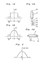
- the glass preform has refractive index difference distribution patterns as shown in Figures 1A and 1B.
- an additive such as Ge0 2 , AI 2 0 3 and Ti0 2 is added to silica glass to increase its refractive index.
- the additive such as Ge0 2 is added to the core to increase the refractive index of the core, thereby achieving a predetermined refractive index difference between the core and the cladding and, thereafter, fluorine is added to lower the refractive index of the whole glass preform while maintaining the refractive index difference between the core and the cladding at the already achieved value, whereupon the apparent amount of the additive added to the core, as determined based on the refractive index of silica (Si0 2 ), is reduced.
- this method there are various problems to be overcome in connection with a procedure of adding fluorine.
- Japanese Patent Publication No. 15682/1980 discloses a procedure in which fluorine is added in the course of flame hydrolysis to form glass fine particles.
- This method has disadvantages such that an absolute amount of fluorine added is small and the required production time is long. This may be due to the fact that moisture contained in the flame reacts with fluorine gas according to, for example, the following reaction formula, thereby yielding HF gas:
- HF erodes glass, particularly quartz and easily reacts with silica glass fine particles formed in the flame.
- This reaction may proceed according to the following reaction formulas (2) and (3). This reaction results in the consumption of the formed glass particles.
- the symbols (s) and (g) represent solid and gas respectively.
- the fluorine-based gas therefore, acts to suppress accumulation of the silica glass fine particles, as the amount of the fluorine-based gas added increases, the rate of accumulation of silica glass fine particles decreases, and finally the silica glass particles are not accumulated at all.
- JP-A-55-67533 on which the pre-characterising part of claim 1 is based discloses a procedure in which a glass soot preform is formed and, thereafter, to the preform is added fluorine by sintering it in an atmosphere containing fluorine. Even in this method, the rate of addition of fluorine is low and, furthermore, the preform is sometimes contaminated with Cu and Fe.
- Another drawback is that in sintering at a temperature higher than 1400°C, the surface of the glass preform is vigorously etched to produce a glass preform having an uneven surface. Still another drawback is that this etching allows easy invasion of impurities contained in a mandrel into the glass soot preform.
- the present invention proposes a method for producing a glass preform for optical fibers by heating a glass soot preform consisting of glass fine particles made mainly of silicon oxide comprising the step of heating the glass soot preform in a gas atmosphere containing at least fluorine or fluorine-based compound to add fluorine to the glass soot preform, and the further step of heating the glass soot preform to make it transparent, characterised in that the method comprises a first step of heating the glass soot preform to dehydrate and to remove impurities therefrom.
- the heating step to make the preform transparent is carried out in a helium gas atmosphere or under reduced pressure.
- a glass soot preform is prepared and, then, it is added with fluorine in a sintering step.
- the glass soot preform to be treated by the method of the invention is preferably in the form of a tube or a rod.
- the glass soot preform i.e. a mass of fine particles of silica glass may be prepared by various commonly used methods. Typical examples of such the methods are the VAD method shown in Figure 2A and the outside vapor phase oxidation (OVPO) method shown in Figure 2B.
- the numeral 1 indicates a combustion burner; the numerals 2, 3, 4 and 5, inlets of gaseous starting materials; the numeral 6, a starting member; and the numeral 7, a mass of fine particles of silica glass.
- the core is doped with, for example, Ge0 2 so that the glass soot preform has a refractive index distribution pattern as shown in Figure 3.
- the glass soot preform is placed in a muffle tube made of pure quartz or of aluminium and then heated and sintered. This sintering process comprises three steps.
- the glass soot preform is dehydrated and impurities are removed therefrom.
- the first heating step is carried out at a temperature of from 800 to 1200°C. If the temperature is lower than 800°C, the impurities cannot be removed and, further, a longer period of time is needed for dehydration. On the other hand, if the temperature is higher than 1,200°C, the glass soot preform tends to shrink and, thus, it becomes difficult to add fluorine to the glass soot preform in the subsequent second heating step.
- the heating time in the first step is usually from about 2 to 4 hours.
- Heating is preferably carried out in a highly pure inert gas atmosphere. Even if it is carried out in an inert gas atmosphere containing chlorine-based gas, the dehydration and removal of impurities may be efficiently accomplished.
- chlorine-based gas C1 2 , SOCL 2 , COCL 2 , CCI 4 , and the like can be used.
- the concentration of the inert gas is preferably adjusted to not less than 80% by volume. Even if, however, the concentration of the inert gas is 0%, no serious problem will be encountered.
- the concentration of the chlorine-based gas is sufficient to be about 10% by volume.
- the second heating step is carried out in order to add fluorine to the glass soot preform.
- the second heat treatment is carried out at a temperature of from 1100 to 1400°C.
- the atmosphere is an inert gas atmosphere containing fluorine gas or a gaseous fluorine-based compound.
- fluorine-based compound CF 4 , SF 6 , SiF 4 , COF 2 and the like can be used.
- the inert gas N 2 , Ar, He, and the like can be used.
- the temperature is raised at a rate of from 2 to 10°C/ min.
- Figure 4 shows the relationship between a temperature-raising rate and the refractive index difference corresponding to the amount of fluorine added to the glass soot preform. It can be seen from Figure 4 that as the temperature-raising rate is lowered, the amount of fluorine added increases.
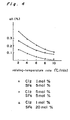
- Figure 5 shows the relationship between the treatment temperature in the atmosphere containing the gaseous fluorine-based compound and the refractive index difference An corresponding to the amount of fluorine added.
- the sintering atmosphere comprises helium gas containing 1 mol% of chlorine gas and 10 mol% of SF 6 , and the refractive index difference An is determined after the heat treatment is performed at each temperature shown for 3 hours. It can be seen from the graph of Figure 5 that the refractive index difference An is larger in a temperature range between 1100 and 1400°C. This demonstrates that this temperature range is suitable for the second heating step.
- the glass soot preform quickly shrinks so that fluorine cannot be efficiently added to the preform.
- the concentration of the fluorine-based compound is preferably not higher than 20 mol%. If the concentration of the fluorine-based gas is too high, the preform is etched with fluorine gas to some extent, but not so seriously as with HF.
- the third heating step is carried out mainly for the purpose of converting the glass soot preform to a transparent one.
- the third heating step is carried out at a temperature of not lower than 1400°C for at least one hour. If the treatment temperature is lower than 1400°C, the fine glass particles are insufficiently sintered so that a certain proportion of the glass fine particles is left unsintered. More preferably the third heat treatment is carried out at a temperature in excess of 1600°C. 1n this case, the sintering process proceeds efficiently and the glass soot preform can be converted into a transparent one in a relatively short period of time.
- the third heating step is carried out in a helium gas atmosphere or under reduced pressure.
- the sintering process for converting the glass soot preform into the transparent one is carried out in an atmosphere of argon gas or nitrogen gas.
- the distribution of glass particle sizes is broad; that is, an irregularity in the particle size of the glass particles is large, if the sintering process is carried out in the usual atmosphere, bubbles are liable to remain during sintering and the glass soot preform shrinks, and consequently the glass soot preform cannot be made transparent desirably.
- the ease of formation of the bubbles is in the following order: If, therefore, the sintering process is carried out in a helium gas atmosphere, a sintered preform containing the bubbles in a greatly reduced amount is produced, since the defoaming action in the helium gas atmosphere is greater than those in argon and nitrogen gas atmospheres. The defoaming can be accelerated also under reduced pressure.
- FIG. 7 An embodiment of the heating mode of the present invention is shown schematically in Figure 7.
- An example of the refractive index distribution of a glass preform produced in this embodiment is shown in Figure 6.
- Figure 6 By comparing Figure 3 with Figure 6, it can be seen that the refractive index of the whole preform is decreased by about 0.2% while maintaining a refractive index difference An of about 1.0% between the center of the core and the cladding.
- a bulk density of the core is made larger than that of the cladding.
- the dehydration of the glass soot preform and the removal of impurities are effected in the first heating step.
- the optical fibers fabricated from the glass soot preform prepared by the method of the invention are greatly reduced in attenuation resulting from impurities. That is, the dehydration of the glass soot preform enables to suppress the formation of HF during the addition of fluorine to the preform. HF, if present in a large amount, erodes the muffle tube and makes impurities contained in the muffle tube walls exposed. Such the exposed impurities contaminate the glass soot preform.
- the impurities are removed from the system in the first heating step, such contamination of the soot preform with the impurities can be prevented.
- CuO even if CuO is present in the atmosphere, it is converted into Cu 2 0 at an elevated temperature of higherthan 800°C according to the following reaction formula, and is removed as C U2 0 gas from the system. In this reaction, as the temperature is raised, the formation of Cu 2 0 gas is accelerated. At a temperature of higher than 1000°C, the CuO impurity is much efficiently removed.
- chlorine gas is added, CuO is converted into CuCI 2 according to the following reaction formula and thus can be easily removed from the system.
- the etching of the glass preform is prevented and thus there can be obtained a glass preform having a smooth surface.
- erosion of, for example, the muffle tube can be prevented.
- a glass soot preform having a refractive index distribution pattern as shown in Figure 3 was placed in a furnace, pure He gas was introduced into the furnace at a rate of 10 I/min, and the soot preform was heated at 600°C for 3 hours. Then, the temperature was raised to 1100°C in 10 minutes. At the same temperature, SF 6 was supplied to the He gas at a rate of 100 ml/min. while raising the temperature to 1400°C at a rate of 3.3°C/min. After keeping the temperature at 1400°C for 1 hour, He gas was introduced into the furance at a rate of 10 I/min, and the temperature in the furnace was raised to 1650°C to convert the glass soot preform into a transparent one. The thus-obtained transparent preform had a refractive index distribution pattern as shown in Figure 6, and the attenuation of 1.2 dB/km at 1.30 micrometers, and the OH content was 0.01 ppm.
- the same procedure as above was repeated with the exception that the heating temperature in the first step was 800°C.
- the attenuation resulting from impurities was 0.8 dB/km at 1.30 micrometers.
- the same procedure as above was repeated with the exception that the heating temperature at the first step was 1100°C.
- the attenuation resulting from impurities was 0.6 dB/km at 1.30 micrometers.
- Example 1 The procedure of Example 1 was repeated with the exception that, in the first heating step, 0.5 to 5 mol % of C1 2 was supplied to the pure He gas atmosphere. In case of adjusting the heating temperature in the first heating step to 1100°C, even if, the glass soot preform was kept at that temperature only for about 10 minutes, the resulting optical fiber did not contain any traces of impurities. This was confirmed by the attenuation characteristics of the optical fiber.
- a glass soot preform having a bulk density of the core of 0.4 g/cm 3 and that of the cladding of 0.2 g/cm 3 was prepared. It was heated to a temperature of from 800 to 1200°C in a He gas atmosphere containing 0.5 to 5 mol % of C1 2 and kept at 1200°C for 1 hour. Then, 2 to 5 mol % of fluorine gas was further added, and the temperature was raised to 1400°C.
- the thus-obtained preform was inserted downwardly in a zone- heating furnace at a rate of 3 to 4 mm/min, said furnace being arranged so that the maximum temperature was 1650°C and being in a He gas atmosphere under reduced pressure, whereupon the preform was converted into a transparent one.
- the core had substantially the same refractive index as that of pure silica, and the cladding has the same refractive index as obtained by the addition of fluorine.
- An optical fiber fabricated from the preform had the attenuation of 0.4 dB/km at 1.30 micrometers.
- the preform was converted into a transparent glass body by heating up to 1500°C while feeding He gas.
- the diameter of the core was 10 times that of the cladding, and the refractive index of the cladding was 0.4% lower than that of quartz.
- This preform was drawn so that the outer diameter was 20 mm and inserted through a quartz glass tube (outer diameter: 32.5 mm; inner diameter: 22 mm), which was then drawn to produce a fiber having an outer diameter of 125 ⁇ m.
- the transmission loss at a wavelength of 1.3 ⁇ m was 1 dB/km.
- the peak at a wavelength of 1.39 pm was less than 5 dB/km.
Landscapes
- Chemical & Material Sciences (AREA)
- Engineering & Computer Science (AREA)
- Chemical Kinetics & Catalysis (AREA)
- Physics & Mathematics (AREA)
- General Chemical & Material Sciences (AREA)
- Life Sciences & Earth Sciences (AREA)
- Thermal Sciences (AREA)
- General Life Sciences & Earth Sciences (AREA)
- Geochemistry & Mineralogy (AREA)
- Manufacturing & Machinery (AREA)
- Materials Engineering (AREA)
- Organic Chemistry (AREA)
- Manufacture, Treatment Of Glass Fibers (AREA)
Priority Applications (1)
| Application Number | Priority Date | Filing Date | Title |
|---|---|---|---|
| AT84307222T ATE38823T1 (de) | 1983-10-20 | 1984-10-19 | Verfahren zum herstellen einer vorform in glas fuer optische fasern. |
Applications Claiming Priority (4)
| Application Number | Priority Date | Filing Date | Title |
|---|---|---|---|
| JP19521083A JPS6090843A (ja) | 1983-10-20 | 1983-10-20 | 光フアイバ用ガラス母材の製造方法 |
| JP195209/83 | 1983-10-20 | ||
| JP58195209A JPS6090842A (ja) | 1983-10-20 | 1983-10-20 | 光フアイバ用ガラス母材の製造方法 |
| JP195210/83 | 1983-10-20 |
Publications (3)
| Publication Number | Publication Date |
|---|---|
| EP0139532A2 EP0139532A2 (en) | 1985-05-02 |
| EP0139532A3 EP0139532A3 (en) | 1986-04-23 |
| EP0139532B1 true EP0139532B1 (en) | 1988-11-23 |
Family
ID=26508989
Family Applications (1)
| Application Number | Title | Priority Date | Filing Date |
|---|---|---|---|
| EP84307222A Expired EP0139532B1 (en) | 1983-10-20 | 1984-10-19 | Method for the production of glass preform for optical fibers |
Country Status (6)
| Country | Link |
|---|---|
| US (1) | US4586943A (da) |
| EP (1) | EP0139532B1 (da) |
| CA (1) | CA1248416A (da) |
| DE (1) | DE3475294D1 (da) |
| DK (1) | DK158940C (da) |
| HK (1) | HK79989A (da) |
Cited By (3)
| Publication number | Priority date | Publication date | Assignee | Title |
|---|---|---|---|---|
| EP1679760A1 (en) | 2005-01-11 | 2006-07-12 | Air Products and Chemicals, Inc. | Electrolytes, cells and methods of forming passivation layers |
| WO2015057499A1 (en) | 2013-10-17 | 2015-04-23 | Lubrizol Advanced Materials, Inc. | Copolymers with a polyacrylic acid backbone as performance enhancers for lithium-ion cells |
| EP2977359A1 (de) | 2014-07-21 | 2016-01-27 | Heraeus Quarzglas GmbH & Co. KG | Verfahren zur Herstellung von mit Fluor dotiertem Quarzglas |
Families Citing this family (39)
| Publication number | Priority date | Publication date | Assignee | Title |
|---|---|---|---|---|
| US5221309A (en) * | 1984-05-15 | 1993-06-22 | Sumitomo Electric Industries, Ltd. | Method for producing glass preform for optical fiber |
| JPS60239337A (ja) * | 1984-05-15 | 1985-11-28 | Sumitomo Electric Ind Ltd | 光フアイバ−用ガラス母材の製造法 |
| JPS60260430A (ja) * | 1984-06-04 | 1985-12-23 | Sumitomo Electric Ind Ltd | フツ素をクラツド部に含有する光フアイバ用母材の製造方法 |
| GB2162168B (en) * | 1984-07-25 | 1988-06-29 | Stc Plc | Optical fibre manufacture |
| US4600442A (en) * | 1984-08-14 | 1986-07-15 | Hughes Aircraft Company | Process for the removal of impurities from optical component materials |
| JPS6186436A (ja) * | 1984-10-05 | 1986-05-01 | Sumitomo Electric Ind Ltd | 光フアイバ用母材の製造方法 |
| CA1271316A (en) * | 1984-12-21 | 1990-07-10 | Koichi Abe | Optical waveguide manufacture |
| DE3500672A1 (de) * | 1985-01-11 | 1986-07-17 | Philips Patentverwaltung | Lichtleitfaser mit fluordotierung und verfahren zu deren herstellung |
| CA1290942C (en) * | 1985-03-18 | 1991-10-22 | Michihisa Kyoto | Method for producing glass preform for optical fiber |
| US5364428A (en) * | 1985-03-18 | 1994-11-15 | Sumitomo Electric Industries, Ltd. | Method for producing glass preform for optical fiber |
| US5203899A (en) * | 1985-03-18 | 1993-04-20 | Sumitomo Electric Industries, Ltd. | Method for producing glass preform for optical fiber |
| JPS6236035A (ja) * | 1985-04-18 | 1987-02-17 | Sumitomo Electric Ind Ltd | 光フアイバ母材の製造方法 |
| JPS61247633A (ja) * | 1985-04-25 | 1986-11-04 | Sumitomo Electric Ind Ltd | 光フアイバ−用ガラス母材の製造方法 |
| JPS62275035A (ja) * | 1985-05-07 | 1987-11-30 | Sumitomo Electric Ind Ltd | 光フアイバ用母材の製造方法 |
| US4620861A (en) * | 1985-11-04 | 1986-11-04 | Corning Glass Works | Method for making index-profiled optical device |
| KR950014101B1 (ko) * | 1987-02-16 | 1995-11-21 | 스미토모덴기고교 가부시키가이샤 | 광섬유용 유리모재의 가열로와 그 유리모재의 제조방법 |
| DE3735532A1 (de) * | 1987-10-21 | 1989-05-03 | Rheydt Kabelwerk Ag | Verfahren zum herstellen einer vorform fuer lichtwellenleiter |
| JPH029727A (ja) * | 1988-06-28 | 1990-01-12 | Sumitomo Electric Ind Ltd | 光フアイバ用母材の製造方法 |
| DE3911745A1 (de) * | 1989-04-11 | 1990-10-25 | Philips Patentverwaltung | Verfahren zur herstellung von glaskoerpern mit bereichen unterschiedlicher optischer brechung |
| AU653411B2 (en) * | 1991-07-19 | 1994-09-29 | Sumitomo Electric Industries, Ltd. | Method for producing glass preform for optical fiber |
| JP2917729B2 (ja) * | 1993-03-03 | 1999-07-12 | 住友電気工業株式会社 | 光ファイバ母材の製造方法 |
| TW371650B (en) * | 1995-12-04 | 1999-10-11 | Sumitomo Electric Industries | Method for producing an optical fiber quartz glass preform |
| US6263706B1 (en) * | 1999-03-30 | 2001-07-24 | Deliso Evelyn M. | Method of controlling fluorine doping in soot preforms |
| TWI233430B (en) * | 2000-01-28 | 2005-06-01 | Shinetsu Chemical Co | Method for manufacturing glass base material, glass base material, and optical fiber |
| JP3865039B2 (ja) * | 2000-08-18 | 2007-01-10 | 信越化学工業株式会社 | 合成石英ガラスの製造方法および合成石英ガラス並びに合成石英ガラス基板 |
| US20020073740A1 (en) * | 2000-12-20 | 2002-06-20 | Dawes Steven B. | Fluorine doping a soot preform |
| US6715322B2 (en) * | 2001-01-05 | 2004-04-06 | Lucent Technologies Inc. | Manufacture of depressed index optical fibers |
| US20050120752A1 (en) * | 2001-04-11 | 2005-06-09 | Brown John T. | Substantially dry, silica-containing soot, fused silica and optical fiber soot preforms, apparatus, methods and burners for manufacturing same |
| US8037717B2 (en) * | 2001-10-26 | 2011-10-18 | Corning Incorporated | Methods and apparatus for pulsed doping or drying a soot preform |
| US6813907B2 (en) * | 2001-11-30 | 2004-11-09 | Corning Incorporated | Fluorine doping a soot preform |
| EP1547981A3 (en) * | 2003-12-25 | 2011-07-06 | Sumitomo Electric Industries, Ltd. | Method of manufacturing fluorine doped silica glass article, preform and optical fiber and optical fiber made by the method |
| JP2006193370A (ja) * | 2005-01-13 | 2006-07-27 | Shin Etsu Chem Co Ltd | 光ファイバ母材及びその製造方法 |
| JP5916966B2 (ja) * | 2014-01-16 | 2016-05-11 | 古河電気工業株式会社 | 光ファイバ母材の製造方法および光ファイバの製造方法 |
| EP3359498B1 (en) * | 2015-10-09 | 2020-12-23 | Prysmian S.p.A. | Method for manufacturing a glass core preform for optical fibres |
| JP2018205357A (ja) * | 2017-05-30 | 2018-12-27 | 株式会社フジクラ | 光ファイバ、光ファイバの製造方法、および光ファイバ母材 |
| US10571628B2 (en) | 2017-11-20 | 2020-02-25 | Corning Incorporated | Low loss optical fiber with core codoped with two or more halogens |
| IT201800009920A1 (it) | 2018-10-30 | 2020-04-30 | Prysmian Spa | Metodo per fabbricare una preforma di vetro per fibre ottiche |
| EP3950611A1 (de) | 2020-08-06 | 2022-02-09 | Heraeus Quarzglas GmbH & Co. KG | Alternative fluorierungsmittel zur herstellung von fluoriertem quarzglas |
| WO2024226254A1 (en) * | 2023-04-28 | 2024-10-31 | Corning Incorporated | Method of manufacturing a porous glass body to lower attenuation of optical fiber made therefrom |
Family Cites Families (8)
| Publication number | Priority date | Publication date | Assignee | Title |
|---|---|---|---|---|
| US3933454A (en) * | 1974-04-22 | 1976-01-20 | Corning Glass Works | Method of making optical waveguides |
| FR2428618A1 (fr) * | 1978-06-16 | 1980-01-11 | Telecommunications Sa | Procede de fabrication d'une ebauche en vue de la realisation d'un guide de lumiere et ebauche obtenue selon le procede |
| JPS6038345B2 (ja) * | 1978-11-07 | 1985-08-31 | 日本電信電話株式会社 | 光伝送用ガラス素材の製造方法 |
| JPS55167149A (en) * | 1979-06-13 | 1980-12-26 | Nippon Telegr & Teleph Corp <Ntt> | Manufacture of anhydrous quartz type fiber base material |
| JPS5844619B2 (ja) * | 1979-09-26 | 1983-10-04 | 日本電信電話株式会社 | 光フアイバ母材の製造法 |
| JPS5915086B2 (ja) * | 1980-05-06 | 1984-04-07 | 株式会社神奈川製作所 | ガラス素材板の同時均等分割装置 |
| JPS5918328B2 (ja) * | 1981-02-10 | 1984-04-26 | 工業技術院長 | 2酸化ゲルマニウム−3酸化アンチモンガラスの製造方法 |
| AU569757B2 (en) * | 1983-10-19 | 1988-02-18 | Nippon Telegraph & Telephone Corporation | Optical fibre preform manufacture |
-
1984
- 1984-10-16 US US06/661,451 patent/US4586943A/en not_active Expired - Lifetime
- 1984-10-17 DK DK497184A patent/DK158940C/da not_active IP Right Cessation
- 1984-10-19 CA CA000465912A patent/CA1248416A/en not_active Expired
- 1984-10-19 DE DE8484307222T patent/DE3475294D1/de not_active Expired
- 1984-10-19 EP EP84307222A patent/EP0139532B1/en not_active Expired
-
1989
- 1989-10-05 HK HK799/89A patent/HK79989A/en not_active IP Right Cessation
Cited By (3)
| Publication number | Priority date | Publication date | Assignee | Title |
|---|---|---|---|---|
| EP1679760A1 (en) | 2005-01-11 | 2006-07-12 | Air Products and Chemicals, Inc. | Electrolytes, cells and methods of forming passivation layers |
| WO2015057499A1 (en) | 2013-10-17 | 2015-04-23 | Lubrizol Advanced Materials, Inc. | Copolymers with a polyacrylic acid backbone as performance enhancers for lithium-ion cells |
| EP2977359A1 (de) | 2014-07-21 | 2016-01-27 | Heraeus Quarzglas GmbH & Co. KG | Verfahren zur Herstellung von mit Fluor dotiertem Quarzglas |
Also Published As
| Publication number | Publication date |
|---|---|
| EP0139532A3 (en) | 1986-04-23 |
| DK497184D0 (da) | 1984-10-17 |
| CA1248416A (en) | 1989-01-10 |
| US4586943A (en) | 1986-05-06 |
| DK158940B (da) | 1990-08-06 |
| DE3475294D1 (en) | 1988-12-29 |
| DK497184A (da) | 1985-04-21 |
| HK79989A (en) | 1989-10-13 |
| EP0139532A2 (en) | 1985-05-02 |
| DK158940C (da) | 1991-01-14 |
Similar Documents
| Publication | Publication Date | Title |
|---|---|---|
| EP0139532B1 (en) | Method for the production of glass preform for optical fibers | |
| EP0140651B1 (en) | Method for production of glass preform for optical fibers | |
| EP0161680B1 (en) | Method for producing glass preform for optical fiber | |
| US5221309A (en) | Method for producing glass preform for optical fiber | |
| EP0151438B1 (en) | Method for producing glass preform for optical fiber | |
| EP0198510B1 (en) | Method of producing glass preform for optical fiber | |
| EP0160244B1 (en) | Quartz glass optical fiber | |
| EP0348935A2 (en) | Method for producing glass preform for optical fiber | |
| EP0175067B1 (en) | Method for producing glass preform for optical fiber | |
| EP0167054B1 (en) | Method for producing glass preform for optical fiber | |
| EP0201937B1 (en) | Method for producing glass preform for optical fiber | |
| JPH0314789B2 (da) | ||
| EP1270522B1 (en) | Method for fabricating optical fiber from preforms, using control of the partial pressure of oxygen during preform dehydration | |
| JPS6238292B2 (da) | ||
| JPS6090843A (ja) | 光フアイバ用ガラス母材の製造方法 | |
| KR870001738B1 (ko) | 광 파이버용 유리모제의 제조방법 | |
| JP2002274876A (ja) | ガラス物品の製造方法 | |
| JPS632902B2 (da) | ||
| JPH0653590B2 (ja) | 弗素添加透明石英ガラス体の製造方法 | |
| JPH0324415B2 (da) | ||
| JP2645717B2 (ja) | 光フアイバ用母材の製造方法 | |
| JPH0656454A (ja) | 光ファイバ母材の製造方法 | |
| JPH0355423B2 (da) | ||
| JPH03183632A (ja) | 光ファイバ用ガラス母材の製造方法 | |
| JPH0660029B2 (ja) | 光フアイバ用母材の製造方法 |
Legal Events
| Date | Code | Title | Description |
|---|---|---|---|
| PUAI | Public reference made under article 153(3) epc to a published international application that has entered the european phase |
Free format text: ORIGINAL CODE: 0009012 |
|
| AK | Designated contracting states |
Designated state(s): AT DE FR GB SE |
|
| RAP1 | Party data changed (applicant data changed or rights of an application transferred) |
Owner name: NIPPON TELEGRAPH AND TELEPHONE CORPORATION Owner name: SUMITOMO ELECTRIC INDUSTRIES LIMITED |
|
| PUAL | Search report despatched |
Free format text: ORIGINAL CODE: 0009013 |
|
| AK | Designated contracting states |
Kind code of ref document: A3 Designated state(s): AT DE FR GB SE |
|
| 17P | Request for examination filed |
Effective date: 19860611 |
|
| 17Q | First examination report despatched |
Effective date: 19870217 |
|
| GRAA | (expected) grant |
Free format text: ORIGINAL CODE: 0009210 |
|
| AK | Designated contracting states |
Kind code of ref document: B1 Designated state(s): AT DE FR GB SE |
|
| REF | Corresponds to: |
Ref document number: 38823 Country of ref document: AT Date of ref document: 19881215 Kind code of ref document: T |
|
| REF | Corresponds to: |
Ref document number: 3475294 Country of ref document: DE Date of ref document: 19881229 |
|
| ET | Fr: translation filed | ||
| PLBE | No opposition filed within time limit |
Free format text: ORIGINAL CODE: 0009261 |
|
| STAA | Information on the status of an ep patent application or granted ep patent |
Free format text: STATUS: NO OPPOSITION FILED WITHIN TIME LIMIT |
|
| 26N | No opposition filed | ||
| EAL | Se: european patent in force in sweden |
Ref document number: 84307222.4 |
|
| REG | Reference to a national code |
Ref country code: FR Ref legal event code: D6 |
|
| REG | Reference to a national code |
Ref country code: GB Ref legal event code: IF02 |
|
| PGFP | Annual fee paid to national office [announced via postgrant information from national office to epo] |
Ref country code: SE Payment date: 20021004 Year of fee payment: 19 |
|
| PGFP | Annual fee paid to national office [announced via postgrant information from national office to epo] |
Ref country code: AT Payment date: 20021011 Year of fee payment: 19 |
|
| PGFP | Annual fee paid to national office [announced via postgrant information from national office to epo] |
Ref country code: FR Payment date: 20031003 Year of fee payment: 20 |
|
| PGFP | Annual fee paid to national office [announced via postgrant information from national office to epo] |
Ref country code: GB Payment date: 20031016 Year of fee payment: 20 |
|
| PG25 | Lapsed in a contracting state [announced via postgrant information from national office to epo] |
Ref country code: AT Free format text: LAPSE BECAUSE OF NON-PAYMENT OF DUE FEES Effective date: 20031019 |
|
| PG25 | Lapsed in a contracting state [announced via postgrant information from national office to epo] |
Ref country code: SE Free format text: LAPSE BECAUSE OF NON-PAYMENT OF DUE FEES Effective date: 20031020 |
|
| PGFP | Annual fee paid to national office [announced via postgrant information from national office to epo] |
Ref country code: DE Payment date: 20031030 Year of fee payment: 20 |
|
| EUG | Se: european patent has lapsed | ||
| PG25 | Lapsed in a contracting state [announced via postgrant information from national office to epo] |
Ref country code: GB Free format text: LAPSE BECAUSE OF EXPIRATION OF PROTECTION Effective date: 20041018 |
|
| REG | Reference to a national code |
Ref country code: GB Ref legal event code: PE20 |