EP0136504B1 - Bobine pour bande en cassette - Google Patents
Bobine pour bande en cassette Download PDFInfo
- Publication number
- EP0136504B1 EP0136504B1 EP84109817A EP84109817A EP0136504B1 EP 0136504 B1 EP0136504 B1 EP 0136504B1 EP 84109817 A EP84109817 A EP 84109817A EP 84109817 A EP84109817 A EP 84109817A EP 0136504 B1 EP0136504 B1 EP 0136504B1
- Authority
- EP
- European Patent Office
- Prior art keywords
- tape
- flange
- reel
- bottom flange
- reel core
- Prior art date
- Legal status (The legal status is an assumption and is not a legal conclusion. Google has not performed a legal analysis and makes no representation as to the accuracy of the status listed.)
- Expired
Links
- 230000002093 peripheral effect Effects 0.000 claims description 10
- 239000000463 material Substances 0.000 description 6
- 238000004804 winding Methods 0.000 description 6
- 239000000088 plastic resin Substances 0.000 description 5
- 230000001788 irregular Effects 0.000 description 3
- 230000037431 insertion Effects 0.000 description 2
- 238000003780 insertion Methods 0.000 description 2
- 238000004519 manufacturing process Methods 0.000 description 2
- 238000000465 moulding Methods 0.000 description 2
- 229920003023 plastic Polymers 0.000 description 2
- 238000010926 purge Methods 0.000 description 2
- 230000003014 reinforcing effect Effects 0.000 description 2
- 230000006641 stabilisation Effects 0.000 description 2
- 238000003466 welding Methods 0.000 description 2
- 239000000853 adhesive Substances 0.000 description 1
- 230000001070 adhesive effect Effects 0.000 description 1
- 230000006835 compression Effects 0.000 description 1
- 238000007906 compression Methods 0.000 description 1
- 230000003247 decreasing effect Effects 0.000 description 1
Images


Classifications
-
- G—PHYSICS
- G11—INFORMATION STORAGE
- G11B—INFORMATION STORAGE BASED ON RELATIVE MOVEMENT BETWEEN RECORD CARRIER AND TRANSDUCER
- G11B23/00—Record carriers not specific to the method of recording or reproducing; Accessories, e.g. containers, specially adapted for co-operation with the recording or reproducing apparatus ; Intermediate mediums; Apparatus or processes specially adapted for their manufacture
- G11B23/02—Containers; Storing means both adapted to cooperate with the recording or reproducing means
- G11B23/037—Single reels or spools
-
- G—PHYSICS
- G11—INFORMATION STORAGE
- G11B—INFORMATION STORAGE BASED ON RELATIVE MOVEMENT BETWEEN RECORD CARRIER AND TRANSDUCER
- G11B23/00—Record carriers not specific to the method of recording or reproducing; Accessories, e.g. containers, specially adapted for co-operation with the recording or reproducing apparatus ; Intermediate mediums; Apparatus or processes specially adapted for their manufacture
- G11B23/02—Containers; Storing means both adapted to cooperate with the recording or reproducing means
- G11B23/04—Magazines; Cassettes for webs or filaments
- G11B23/08—Magazines; Cassettes for webs or filaments for housing webs or filaments having two distinct ends
- G11B23/087—Magazines; Cassettes for webs or filaments for housing webs or filaments having two distinct ends using two different reels or cores
- G11B23/08707—Details
- G11B23/08728—Reels or cores; positioning of the reels in the cassette
Definitions
- the present invention relates to a tape reel in which an improvement is made on a surface shape of a flange of a tape reel.
- Conventional tape reels as described in GB-A-2009 101, have an inner surface on which the tape edge contacts formed as a simple flat surface.
- One of the problem of the conventional tape reel is in that since the inner surface of the flange is formed as a simple flat surface, in case the recording tape which is a thin and soft strip is wound on the reel core with the one end of the tape fixed to the reel core, there tends to swell air between one tape already wound and another tape which is wound on the already wound tape (referred to as tape layer hereinafter) and then the air is prevented from being exhausted, whereby the air is enclosed between the laminatedly wound tape layers.
- the air enclosed between the wound tape layers is purged when the winding force of the tape is increased due to increment of the volume of the roll of the tape and the portion of the tape layer where the air purge occurs is forced to shift in a direction of width of the tape as the air is purged, then there occurs irregular winding of the tape.
- irregular winding may occur particularly during the fast winding or rewinding.
- one or more reinforcing ribs may be formed on the outer surface of the flange of the tape reel with the inner surface of the flange made flat.
- the flange In this arrangement, if such ribs are merely added, there may occur difference of the thickness between the ribbed portion and non-ribbed portion.
- the flange In reinforcing the flange if both inner and outer surfaces of the flange are made flat, the flange must be thick and it is difficult to make the over all surfaces of the flange flat.
- DE-B-1 211 461 describes a tape reel having two parallel flanges provided with through-holes and radial grooves.
- the through-holes are provided for saving weight and mass and the grooves act only for stabilisation because the extensive holes tend to lower the stabilisation. Because of the holes, the flanges are not continuous and not of generally equal thickness.
- the object of the present invention is to enable to wind respective tapes closely preventing irregular winding of the tapes by purging out undesired air between the respective tapes.
- the tape reel according to the invention has the features of Claim 1.
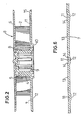
- Fig. 1 illustrates a tape cartridge for video recording.
- a pair of tape reels 3 so as to have a recording tape 2 taken out from one tape reel 3 to the front portion of the cartridge case 1 and taken up onto the other tape reel 3.
- each of the tape reels 3 has flanges 6, 7 at the top and the bottom of the reel core 5 which has a cylindrical outer peripheral wall 4.
- the reel core 5 and the lower flange 7 are molded in one-piece using plastic resin materials, and the upper flange 6 is molded as a separate member with a transparent plastic resin material. Thereafter, it is combined by caulking at the upper end of the reel core 5 by supersonic wave welding.
- One end portion of the recording tape 2 is clamped to a portion of the reel core 5 using a clamp piece 8.
- a drive shaft insertion hole 9 is defined so as to receive a driving shaft of a video deck (not shown) from below.
- a reference surface 10 in the form of an annular rib is projectingly formed on the lower end face of the reel core 5 surrounding the drive shaft insertion hole 9.
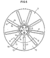
- a plurality of grooves 11 are defined so as to radially extend on the inside surface or the upper surface of the lower flange 7 with which the lower edge of the recording tape 2 is slidably supported.
- the respective grooves 11 radially extend between the inner positions near the reel core 5 and the outer positions near the outer peripheral edge of the Iwer flange 7 with a predetermined angular spaces in the circumferential direction.
- the flat areas 13 and the bottom wall of the grooves 11 in the lower flange 7 are continued in circumferential direction with an approximately the same wall thickness.
- the boundary 14 between the groove 11 and the flat area 13 is formed in a smooth curved surface, so that the flow of the plastic rein material is smoothed when the tape reel is molded so as to assure a smooth contact of the recording tape edge with the surface of the lower flange 7 for preventing damage of the recording tape.
- grooves 11 are not formed is formed into a flat surface continued flush with the surface of the flat area 13 over the whole circumference.
- the outer peripheral annular portion 15 of the lower flange 7 has also a uniform wall thickness over the whole circumference of the lower flange.
- the inside or upper suface of the lower flange 7 is slightly downwardly inclined with the central portion of the flange high and the outer peripheral portion low.
- the peripheral annular portion 15 on the upper surface of the lower flange 7 is so defined that each position on the same circle coaxial with the center of the flange has the same height relative to the reference surface 10.
- the upper flange 6 is made transparent, and the cartridge case 1 is provided on its upper surface with a transparent window 17, so that an operator can see the rotation of tape reels 3, especially the direction of rotation thereof together with the tape winding volume, by seeing a part of the groove 11 which is not concealed by the roll of the recording tape 2 from outside of the cartridge case 1.
- the reel core 5 and the lower flange 7 are molded in one-piece by plastic resin material. However, they may respectively be molded separately and then combined in one-piece by caulking by supersonic welding, or by the aid of an adhesive.
- the grooves 11 may be slightly separated from the reel core 5 as illustrated, but may be continued to the reel core 5.
- the lower flange of the tape reel is formed with a generally equal thickness by providing the radial grooves on the surface for supporting the recording tape and the projected ribs complementarily to the grooves on the opposite surface of the flange, whereby during molding of the tape reel, flow of the plastic resin can be improved so that the flange can be molded without undesired deformation, resulting in improving the geometric accuracy of the tape reel, thus the tape can be regularly wound by the help of grooves through which undesired air can be exhausted.
- the tape reel can be made as thin as possible keeping a desired mechanical strength, so that when manufacturing the tape reel, volume of the material and the production cost can be decreased.
Landscapes
- Storage Of Web-Like Or Filamentary Materials (AREA)
Claims (2)
Applications Claiming Priority (2)
| Application Number | Priority Date | Filing Date | Title |
|---|---|---|---|
| JP130113/83U | 1983-08-22 | ||
| JP1983130113U JPS6056989U (ja) | 1983-08-22 | 1983-08-22 | テ−プカ−トリツジ |
Publications (2)
| Publication Number | Publication Date |
|---|---|
| EP0136504A1 EP0136504A1 (fr) | 1985-04-10 |
| EP0136504B1 true EP0136504B1 (fr) | 1988-11-30 |
Family
ID=15026258
Family Applications (1)
| Application Number | Title | Priority Date | Filing Date |
|---|---|---|---|
| EP84109817A Expired EP0136504B1 (fr) | 1983-08-22 | 1984-08-17 | Bobine pour bande en cassette |
Country Status (5)
| Country | Link |
|---|---|
| US (1) | US4932604A (fr) |
| EP (1) | EP0136504B1 (fr) |
| JP (1) | JPS6056989U (fr) |
| KR (1) | KR850002145A (fr) |
| DE (1) | DE3475447D1 (fr) |
Families Citing this family (26)
| Publication number | Priority date | Publication date | Assignee | Title |
|---|---|---|---|---|
| JPS6173290A (ja) * | 1984-09-17 | 1986-04-15 | Sony Corp | テ−プカセツト |
| DE8606397U1 (de) * | 1986-03-08 | 1986-08-07 | Basf Ag, 6700 Ludwigshafen | Bandklammer für eine Bandspule mit oder ohne mindestens einen Seitenflansch und dafür geeignete Bandspule |
| JPH0763982B2 (ja) * | 1986-05-26 | 1995-07-12 | ポリプラスチックス株式会社 | テ−プリ−ルの製造方法 |
| EP0247822A3 (fr) * | 1986-05-26 | 1989-05-17 | Polyplastics Co. Ltd. | Procédé de fabrication d'une bobine pour bande |
| JPH0548309Y2 (fr) * | 1987-02-27 | 1993-12-22 | ||
| JP2687496B2 (ja) * | 1988-10-31 | 1997-12-08 | ソニー株式会社 | テープリール |
| US5127597A (en) * | 1989-09-16 | 1992-07-07 | Skc Limited | Tape reel assembly with improved reel plate mounting |
| US5089924A (en) * | 1989-12-18 | 1992-02-18 | Minnesota Mining And Manufacturing Company | Tape cassette with wear pad comprising polyolefin sheet and polyamide adhesive layer |
| DE9003809U1 (fr) * | 1990-04-02 | 1990-06-28 | Basf Ag, 6700 Ludwigshafen, De | |
| US5544834A (en) * | 1990-11-19 | 1996-08-13 | Wti International Corporation | Video tape cassette |
| FR2674980B1 (fr) * | 1991-04-04 | 1994-01-21 | Dypy | Cassette pour produit en bande. |
| KR930014536A (ko) * | 1991-12-19 | 1993-07-23 | 오오가 노리오 | 자기테이프 카세트와 테이프릴 및 이를 제조하는 금속주형 |
| CA2105116A1 (fr) * | 1992-09-14 | 1994-03-15 | Robert C. Martin | Cartouche a bobine unique munie d'une flasque etroite comportant des lumieres |
| EP0682342B1 (fr) * | 1994-04-20 | 1999-09-22 | Fuji Photo Film Co., Ltd. | Bobine de bande comportant des rainures de déchargement d'air formées dans un flasque |
| JP3003378U (ja) * | 1994-04-20 | 1994-10-18 | 富士写真フイルム株式会社 | テープリール |
| JP3033685B2 (ja) * | 1996-06-13 | 2000-04-17 | ティーディーケイ株式会社 | テープカセットにおけるテープリール |
| JP3498884B2 (ja) * | 1996-09-20 | 2004-02-23 | 富士写真フイルム株式会社 | 磁気テープカセット用リール |
| JP2001006319A (ja) * | 1999-06-23 | 2001-01-12 | Fuji Photo Film Co Ltd | 磁気テープカセットのテープリール |
| US6302344B1 (en) | 1999-07-01 | 2001-10-16 | Chen K. Su | Lightweight video cassette |
| JP2002133817A (ja) | 2000-10-30 | 2002-05-10 | Sony Corp | テープカセット |
| JP2003331554A (ja) * | 2002-05-09 | 2003-11-21 | Fuji Photo Film Co Ltd | 記録テープカセット |
| JP2005222611A (ja) * | 2004-02-05 | 2005-08-18 | Fuji Photo Film Co Ltd | テープドライブシステム |
| US7147180B1 (en) | 2004-04-30 | 2006-12-12 | Storage Technology Corporation | Tape reel with self-generating negative pressure |
| US20060131461A1 (en) * | 2004-12-17 | 2006-06-22 | Tandberg Storage Asa | Reel for tape-like material with air evacuation for enhanced packing of the reeled material |
| US7434320B2 (en) | 2005-02-17 | 2008-10-14 | Aston Iii Walter Mathew | Blade grip for a knife and method of use |
| JP4673759B2 (ja) * | 2006-01-24 | 2011-04-20 | 日立マクセル株式会社 | テープ用リール及びその製造方法 |
Family Cites Families (10)
| Publication number | Priority date | Publication date | Assignee | Title |
|---|---|---|---|---|
| BE360961A (fr) * | 1929-05-29 | 1929-06-29 | ||
| US2649260A (en) * | 1950-05-26 | 1953-08-18 | Reynolds Metals Co | Field reel for cable coil |
| DE1211461B (de) * | 1962-09-06 | 1966-02-24 | Siemens Ag | Spulenkern, insbesondere fuer bandfoermige Aufzeichnungstraeger |
| JPS5256815Y2 (fr) * | 1972-11-13 | 1977-12-22 | ||
| JPS6037412Y2 (ja) * | 1977-11-18 | 1985-11-07 | ポリプラスチックス株式会社 | 面振れの少ないテ−プリ−ル |
| JPS5728311Y2 (fr) * | 1977-12-16 | 1982-06-21 | ||
| JPS5587352A (en) * | 1978-12-25 | 1980-07-02 | Nifco Inc | Tape reel for video cassette |
| JPS56115783U (fr) * | 1980-02-05 | 1981-09-04 | ||
| US4485990A (en) * | 1982-03-10 | 1984-12-04 | Hitachi Maxell, Ltd. | Recording tape cassette |
| JPS59186180A (ja) * | 1983-04-08 | 1984-10-22 | Hitachi Ltd | 磁気テ−プカ−トリッヂ |
-
1983
- 1983-08-22 JP JP1983130113U patent/JPS6056989U/ja active Pending
-
1984
- 1984-08-17 DE DE8484109817T patent/DE3475447D1/de not_active Expired
- 1984-08-17 EP EP84109817A patent/EP0136504B1/fr not_active Expired
- 1984-08-21 KR KR1019840005040A patent/KR850002145A/ko not_active Application Discontinuation
-
1987
- 1987-08-03 US US07/081,612 patent/US4932604A/en not_active Expired - Lifetime
Also Published As
| Publication number | Publication date |
|---|---|
| DE3475447D1 (en) | 1989-01-05 |
| EP0136504A1 (fr) | 1985-04-10 |
| KR850002145A (ko) | 1985-05-06 |
| US4932604A (en) | 1990-06-12 |
| JPS6056989U (ja) | 1985-04-20 |
Similar Documents
| Publication | Publication Date | Title |
|---|---|---|
| EP0136504B1 (fr) | Bobine pour bande en cassette | |
| US4726534A (en) | Convertible reel assembly | |
| US5209424A (en) | Single reel cartridge with thinner cover and deep label recess | |
| US4340188A (en) | Winding hub for materials in strip form | |
| US5699973A (en) | Tape reel having air discharging grooves formed in flange | |
| US5829712A (en) | Magnetic tape cassette reel | |
| US5167378A (en) | Video cassette reel insert for varying tape storage capacity | |
| US3724771A (en) | Hub-platform assembly and loop-sizing method | |
| EP1202275B1 (fr) | Cassette à bande | |
| CN100358041C (zh) | 磁带盒的控带盘及磁带盒 | |
| US7152826B2 (en) | Tape reel | |
| EP0813200B1 (fr) | Bobine de bande pour cassette à bande | |
| KR950004529B1 (ko) | 단일부품으로 된 테이프 릴, 그 테이프 카세트 및 이들의 제조방법 | |
| JP4579099B2 (ja) | 磁気テープ巻取り用リールおよびその製造方法、並びにテープカートリッジ | |
| JP2002251859A (ja) | テープリール | |
| EP0459368A2 (fr) | Bobine de bande permettant d'empêcher l'endommagement de la bande | |
| EP0682342B1 (fr) | Bobine de bande comportant des rainures de déchargement d'air formées dans un flasque | |
| JPH0419654Y2 (fr) | ||
| JPS5822308Y2 (ja) | テ−プリ−ル | |
| JPH0713105Y2 (ja) | リール | |
| US5516056A (en) | Videotape cassette | |
| KR200165312Y1 (ko) | 비디오 테이프 카세트의 릴 다운 | |
| JPH0713102Y2 (ja) | 磁気テープカセット | |
| US5561574A (en) | Method for manufacturing lifter for a disc cartridge and feed stock therefor | |
| JPS6134378Y2 (fr) |
Legal Events
| Date | Code | Title | Description |
|---|---|---|---|
| PUAI | Public reference made under article 153(3) epc to a published international application that has entered the european phase |
Free format text: ORIGINAL CODE: 0009012 |
|
| AK | Designated contracting states |
Designated state(s): DE GB |
|
| 17P | Request for examination filed |
Effective date: 19851003 |
|
| 17Q | First examination report despatched |
Effective date: 19861218 |
|
| GRAA | (expected) grant |
Free format text: ORIGINAL CODE: 0009210 |
|
| AK | Designated contracting states |
Kind code of ref document: B1 Designated state(s): DE GB |
|
| REF | Corresponds to: |
Ref document number: 3475447 Country of ref document: DE Date of ref document: 19890105 |
|
| PLBE | No opposition filed within time limit |
Free format text: ORIGINAL CODE: 0009261 |
|
| STAA | Information on the status of an ep patent application or granted ep patent |
Free format text: STATUS: NO OPPOSITION FILED WITHIN TIME LIMIT |
|
| 26N | No opposition filed | ||
| REG | Reference to a national code |
Ref country code: GB Ref legal event code: IF02 |
|
| PGFP | Annual fee paid to national office [announced via postgrant information from national office to epo] |
Ref country code: GB Payment date: 20030813 Year of fee payment: 20 |
|
| PGFP | Annual fee paid to national office [announced via postgrant information from national office to epo] |
Ref country code: DE Payment date: 20030828 Year of fee payment: 20 |
|
| PG25 | Lapsed in a contracting state [announced via postgrant information from national office to epo] |
Ref country code: GB Free format text: LAPSE BECAUSE OF EXPIRATION OF PROTECTION Effective date: 20040816 |
|
| REG | Reference to a national code |
Ref country code: GB Ref legal event code: PE20 |