EP0136504A1 - Bobine pour bande en cassette - Google Patents
Bobine pour bande en cassette Download PDFInfo
- Publication number
- EP0136504A1 EP0136504A1 EP84109817A EP84109817A EP0136504A1 EP 0136504 A1 EP0136504 A1 EP 0136504A1 EP 84109817 A EP84109817 A EP 84109817A EP 84109817 A EP84109817 A EP 84109817A EP 0136504 A1 EP0136504 A1 EP 0136504A1
- Authority
- EP
- European Patent Office
- Prior art keywords
- tape
- flange
- outer peripheral
- reel
- grooves
- Prior art date
- Legal status (The legal status is an assumption and is not a legal conclusion. Google has not performed a legal analysis and makes no representation as to the accuracy of the status listed.)
- Granted
Links
- 230000002093 peripheral effect Effects 0.000 claims description 14
- 239000000463 material Substances 0.000 abstract description 11
- 239000000088 plastic resin Substances 0.000 abstract description 11
- 238000004804 winding Methods 0.000 abstract description 5
- 238000000034 method Methods 0.000 abstract description 3
- 238000000465 moulding Methods 0.000 abstract description 2
- 238000004519 manufacturing process Methods 0.000 description 3
- 238000003780 insertion Methods 0.000 description 2
- 230000037431 insertion Effects 0.000 description 2
- 238000003466 welding Methods 0.000 description 2
- 239000000853 adhesive Substances 0.000 description 1
- 230000001070 adhesive effect Effects 0.000 description 1
- 238000005266 casting Methods 0.000 description 1
- 238000001816 cooling Methods 0.000 description 1
- 230000003247 decreasing effect Effects 0.000 description 1
- 230000002950 deficient Effects 0.000 description 1
- 230000001788 irregular Effects 0.000 description 1
- 229920003023 plastic Polymers 0.000 description 1
- 230000003014 reinforcing effect Effects 0.000 description 1
Images


Classifications
-
- G—PHYSICS
- G11—INFORMATION STORAGE
- G11B—INFORMATION STORAGE BASED ON RELATIVE MOVEMENT BETWEEN RECORD CARRIER AND TRANSDUCER
- G11B23/00—Record carriers not specific to the method of recording or reproducing; Accessories, e.g. containers, specially adapted for co-operation with the recording or reproducing apparatus ; Intermediate mediums; Apparatus or processes specially adapted for their manufacture
- G11B23/02—Containers; Storing means both adapted to cooperate with the recording or reproducing means
- G11B23/037—Single reels or spools
-
- G—PHYSICS
- G11—INFORMATION STORAGE
- G11B—INFORMATION STORAGE BASED ON RELATIVE MOVEMENT BETWEEN RECORD CARRIER AND TRANSDUCER
- G11B23/00—Record carriers not specific to the method of recording or reproducing; Accessories, e.g. containers, specially adapted for co-operation with the recording or reproducing apparatus ; Intermediate mediums; Apparatus or processes specially adapted for their manufacture
- G11B23/02—Containers; Storing means both adapted to cooperate with the recording or reproducing means
- G11B23/04—Magazines; Cassettes for webs or filaments
- G11B23/08—Magazines; Cassettes for webs or filaments for housing webs or filaments having two distinct ends
- G11B23/087—Magazines; Cassettes for webs or filaments for housing webs or filaments having two distinct ends using two different reels or cores
- G11B23/08707—Details
- G11B23/08728—Reels or cores; positioning of the reels in the cassette
Definitions
- the present invention relates to a tape cartridge having a case and tape reels rotatably mounted in the case for winding a recording tape.
- the inside surfaces of both of the top flange and the bottom flange are formed flat and the outside surfaces thereof being formed either flat or with radial reinforcing ribs.
- plastic resin materials are injected from a gate set at the position of the die corresponding to the center of the tape reel and flow in the space for the flange and the ribs.
- plastic resin materials for the ribs and the other parts such as the flat wide flange portion due to a difference of thickness between the ribs and the flat flange portion, so that there occur defective filling of plastic resin materials or internal strain due to the difference of shrinkages of the plastic resin materials during the process of cooling of casting mold.
- the flanges In a case where the ribs are not formed on the flanges, i.e., the flanges are flat, the flanges have to be made rather thicker so as to maintain the mechanical strength of the flanges, thereby giving a disadvantage of lowering the moldability of the tape reels.
- an essential object of the present invention is to provide a recording tape cartridge having a tape reel arrangement which is easy to manufacture with a high geometric precision of the tape reel keeping the mechanical strength.
- the other object of the present invention is to provide a tape reel for use in a recording tape cartridge with a thin flange portion for enabling to decrease the necessary volume of the plastic resin material and to improve the productivity or moldability of the tape reel.
- a tape cartridge comprising a cartridge case 1 for containing tape reels 3 on which a tape 2 is to be wound, each of said tape reels 3 comprising a reel core 5 having a circular outer peripheral wall surface 4 and a flange 7 having a generally flat part 13 for slidably supporting the lower edges portions of the tape 2, said tape cartridge is characterized in that said flange 7 is provided with a plurality of grooves 11 each extending radially from the position near the reel core 5 to the position near the outer peripheral edge of the flange 7 with a predetermined interval in the circumferential direction forming a plurality of projected ribs 12 on the opposite surface of the flange 7 so as to make the whole part of the flange 7 in a generally equal thickness and that the outer peripheral edge portion 15 of the flange 7 is not formed with the grooves so that the outer peripheral edge portion 15 is smoothly continued flush with the flat part 13.
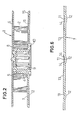
- Fig. 1 illustrates a tape cartridge for video recording.
- a pair of tape reels 3 so as to have a recording tape 2 taken out from one tape reel 3 to the front portion of the cartridge case 1 and taken up onto the other tape reel 3.
- each of the tape reels 3 has flanges 6, 7 at the top and the bottom of the reel core 5 which has a cylindrical outer peripheral wall 4.
- the reel core 5 and the lower flange 7 are molded in one-piece using plastic resin materials, and the upper flange 6 is molded as a separate member with a transparent plastic resin material. Thereafter, it is combined by caulking at the upper end of the reel core 5 by supersonic wave welding.
- One end portion of the recording tape 2 is clamped to a portion of the reel core 5 using a clamp piece 8.
- a drive shaft insertion hole 9 is defined so as to receive a driving shaft of a video deck (not shown) from below.
- a reference surface 10 in the form of an annular rib is projectingly formed on the lower end face of the reel core 5 surrounding the drive shaft insertion hole 9.
- a plurality of grooves 11 are defined so as to radially extend on the inside surface or the upper surface of the lower flange 7 with which the lower edge of the recording tape 2 is slidably supported.
- the respective grooves 11 radially extend between the inner positions near the reel core 5 and the outer positions near the outer peripheral edge of the lower flange 7 with a predetermined angular spaces in the circumferential direction.
- the flat areas 13 and the bottom wall of the grooves 11 in the lower flange 7 are continued in circumferential direction with an approximately the same wall thickness.
- the boundary 14 between the groove 11 and the flat area 13 is formed in a smooth curved surface, so that the flow of the plastic resin material is smoothed when the tape reel is molded so as to assure a smooth contact of the recording tape edge with the surface of the lower flange 7 for preventing damage of the recording tape.
- the upper surface of the outer peripheral annular portion 15 of the lower flange 7 on which the grooves 11 are not formed is formed into a flat surface continued flush with the surface of the flat area 13 over the whole circumference.
- the outer peripheral annular portion 15 of the lower flange 7 has also a uniform wall thickness over the whole circumference of the lower flange, In the preferred embodiment, the inside or upper surface of the lower flange 7 is slightly downwardly inclined with the central portion of the flange high and the outer peripheral portion low. In this arrangement, it is noted that, except for the grooved portion, the peripheral annular portion 15 on the upper surface of the lower flange 7 is so defined that each position on the same circle coaxial with the center of the flange has the same height relative to the reference surface 10.
- the upper flange 6 is made transparent, and the cartridge case 1 is provided on its upper surface with a transparent window 17, so that an operator can see the rotation of tape reels 3, especially the direction of rotation thereof together with the tape winding volume, by seeing a part of the groove 11 which is not concealed by the roll of the recording tape 2 from outside of the cartridge case 1.
- the upper flange 6 is not essentially necessary.
- the present invention may be applicable to a so-called one flange type tape reel. It is desirable that the reel core 5 and the lower flange 7 are molded in one-piece by plastic resin material. However, they may respectively be molded separately and then combined in one-piece by caulking by supersonic welding, or by the aid of an adhesive.
- the grooves 11 are not necessarily formed radially at equal intervals. It may be possible to form a couple of symmetric grooves 11 so as to extend radially on opposite areas with respect to the center of the tape reel 2.
- the grooves 11 may be slightly separated from the reel core 5 ' as illustrated, but may be continued to the reel core 5.
- the lower flange of the tape reel is formed with a generally equal thickness by providing the radial grooves on the surface for supporting the recording tape and the projected ribs complementarily to the grooves on the opposite surface of the flange, whereby during moding of the tape reel, flow of the plastic resin can be improved so that the flange can be molded without undesired deformation, resulting in improving the geometric accuracy of the tape reel, thus the tape can be regularly wound by the help of grooves through which undesired air can be exhausted.
- the tape reel can be made as thin as possible keeping a desired mechanical strength, so that when manufacturing the tape reel, volume of the material and the production cost can be decreased.
Landscapes
- Storage Of Web-Like Or Filamentary Materials (AREA)
Applications Claiming Priority (2)
| Application Number | Priority Date | Filing Date | Title |
|---|---|---|---|
| JP1983130113U JPS6056989U (ja) | 1983-08-22 | 1983-08-22 | テ−プカ−トリツジ |
| JP130113/83U | 1983-08-22 |
Publications (2)
| Publication Number | Publication Date |
|---|---|
| EP0136504A1 true EP0136504A1 (fr) | 1985-04-10 |
| EP0136504B1 EP0136504B1 (fr) | 1988-11-30 |
Family
ID=15026258
Family Applications (1)
| Application Number | Title | Priority Date | Filing Date |
|---|---|---|---|
| EP84109817A Expired EP0136504B1 (fr) | 1983-08-22 | 1984-08-17 | Bobine pour bande en cassette |
Country Status (5)
| Country | Link |
|---|---|
| US (1) | US4932604A (fr) |
| EP (1) | EP0136504B1 (fr) |
| JP (1) | JPS6056989U (fr) |
| KR (1) | KR850002145A (fr) |
| DE (1) | DE3475447D1 (fr) |
Cited By (12)
| Publication number | Priority date | Publication date | Assignee | Title |
|---|---|---|---|---|
| EP0175347A2 (fr) * | 1984-09-17 | 1986-03-26 | Sony Corporation | Cassette de bande |
| EP0236917A1 (fr) * | 1986-03-08 | 1987-09-16 | BASF Aktiengesellschaft | Bride de fixation de bande pour une bobine de bande avec ou sans au moins une joue latérale et bobine de bande pour celle-ci |
| EP0247821A2 (fr) * | 1986-05-26 | 1987-12-02 | Polyplastics Co. Ltd. | Procédé de fabrication d'une bobine pour bande |
| EP0247822A2 (fr) * | 1986-05-26 | 1987-12-02 | Polyplastics Co. Ltd. | Procédé de fabrication d'une bobine pour bande |
| EP0281292A2 (fr) * | 1987-02-27 | 1988-09-07 | Sony Corporation | Bobine de cassette avec un indicateur de volume de bande sur le flasque supérieur |
| US5054709A (en) * | 1988-10-31 | 1991-10-08 | Sony Corporation | Tape cassette reel having upper flanges molded therewith |
| FR2674980A1 (fr) * | 1991-04-04 | 1992-10-09 | Dypy | Cassette pour produit en bande. |
| EP0549289A2 (fr) * | 1991-12-19 | 1993-06-30 | Sony Corporation | Cassette à bande magnétique |
| EP0588219A2 (fr) * | 1992-09-14 | 1994-03-23 | Minnesota Mining And Manufacturing Company | Cassette à bobine comportant des flasques minces à ouvertures |
| EP0682342A2 (fr) * | 1994-04-20 | 1995-11-15 | Fuji Photo Film Co., Ltd. | Bobine de bande comportant des rainures de déchargement d'air formées dans un flasque |
| EP0813200A2 (fr) * | 1996-06-13 | 1997-12-17 | TDK Corporation | Bobine de bande pour cassette à bande |
| US5699973A (en) * | 1994-04-20 | 1997-12-23 | Fuji Photo Film Co., Ltd. | Tape reel having air discharging grooves formed in flange |
Families Citing this family (14)
| Publication number | Priority date | Publication date | Assignee | Title |
|---|---|---|---|---|
| US5127597A (en) * | 1989-09-16 | 1992-07-07 | Skc Limited | Tape reel assembly with improved reel plate mounting |
| US5089924A (en) * | 1989-12-18 | 1992-02-18 | Minnesota Mining And Manufacturing Company | Tape cassette with wear pad comprising polyolefin sheet and polyamide adhesive layer |
| DE9003809U1 (fr) * | 1990-04-02 | 1990-06-28 | Basf Ag, 6700 Ludwigshafen, De | |
| US5544834A (en) * | 1990-11-19 | 1996-08-13 | Wti International Corporation | Video tape cassette |
| JP3498884B2 (ja) * | 1996-09-20 | 2004-02-23 | 富士写真フイルム株式会社 | 磁気テープカセット用リール |
| JP2001006319A (ja) * | 1999-06-23 | 2001-01-12 | Fuji Photo Film Co Ltd | 磁気テープカセットのテープリール |
| US6302344B1 (en) | 1999-07-01 | 2001-10-16 | Chen K. Su | Lightweight video cassette |
| JP2002133817A (ja) * | 2000-10-30 | 2002-05-10 | Sony Corp | テープカセット |
| JP2003331554A (ja) * | 2002-05-09 | 2003-11-21 | Fuji Photo Film Co Ltd | 記録テープカセット |
| JP2005222611A (ja) * | 2004-02-05 | 2005-08-18 | Fuji Photo Film Co Ltd | テープドライブシステム |
| US7147180B1 (en) | 2004-04-30 | 2006-12-12 | Storage Technology Corporation | Tape reel with self-generating negative pressure |
| US20060131461A1 (en) * | 2004-12-17 | 2006-06-22 | Tandberg Storage Asa | Reel for tape-like material with air evacuation for enhanced packing of the reeled material |
| US7434320B2 (en) | 2005-02-17 | 2008-10-14 | Aston Iii Walter Mathew | Blade grip for a knife and method of use |
| JP4673759B2 (ja) * | 2006-01-24 | 2011-04-20 | 日立マクセル株式会社 | テープ用リール及びその製造方法 |
Citations (4)
| Publication number | Priority date | Publication date | Assignee | Title |
|---|---|---|---|---|
| DE1211461B (de) * | 1962-09-06 | 1966-02-24 | Siemens Ag | Spulenkern, insbesondere fuer bandfoermige Aufzeichnungstraeger |
| GB2009101A (en) * | 1977-11-18 | 1979-06-13 | Polyplastics Co | A Tape Reel |
| DE2952350A1 (de) * | 1978-12-25 | 1980-07-03 | Nifco Inc | Bandrolle fuer video-kassetten |
| DE3103823A1 (de) * | 1980-02-05 | 1981-12-10 | TDK Electronics Co., Ltd., Tokyo | Ring mit rippe zum aufwickeln von magnetband |
Family Cites Families (6)
| Publication number | Priority date | Publication date | Assignee | Title |
|---|---|---|---|---|
| BE360961A (fr) * | 1929-05-29 | 1929-06-29 | ||
| US2649260A (en) * | 1950-05-26 | 1953-08-18 | Reynolds Metals Co | Field reel for cable coil |
| JPS5256815Y2 (fr) * | 1972-11-13 | 1977-12-22 | ||
| JPS5728311Y2 (fr) * | 1977-12-16 | 1982-06-21 | ||
| US4485990A (en) * | 1982-03-10 | 1984-12-04 | Hitachi Maxell, Ltd. | Recording tape cassette |
| JPS59186180A (ja) * | 1983-04-08 | 1984-10-22 | Hitachi Ltd | 磁気テ−プカ−トリッヂ |
-
1983
- 1983-08-22 JP JP1983130113U patent/JPS6056989U/ja active Pending
-
1984
- 1984-08-17 EP EP84109817A patent/EP0136504B1/fr not_active Expired
- 1984-08-17 DE DE8484109817T patent/DE3475447D1/de not_active Expired
- 1984-08-21 KR KR1019840005040A patent/KR850002145A/ko not_active Application Discontinuation
-
1987
- 1987-08-03 US US07/081,612 patent/US4932604A/en not_active Expired - Lifetime
Patent Citations (4)
| Publication number | Priority date | Publication date | Assignee | Title |
|---|---|---|---|---|
| DE1211461B (de) * | 1962-09-06 | 1966-02-24 | Siemens Ag | Spulenkern, insbesondere fuer bandfoermige Aufzeichnungstraeger |
| GB2009101A (en) * | 1977-11-18 | 1979-06-13 | Polyplastics Co | A Tape Reel |
| DE2952350A1 (de) * | 1978-12-25 | 1980-07-03 | Nifco Inc | Bandrolle fuer video-kassetten |
| DE3103823A1 (de) * | 1980-02-05 | 1981-12-10 | TDK Electronics Co., Ltd., Tokyo | Ring mit rippe zum aufwickeln von magnetband |
Cited By (24)
| Publication number | Priority date | Publication date | Assignee | Title |
|---|---|---|---|---|
| EP0175347A2 (fr) * | 1984-09-17 | 1986-03-26 | Sony Corporation | Cassette de bande |
| EP0175347A3 (en) * | 1984-09-17 | 1986-12-30 | Sony Corporation | A tape cassette |
| EP0175347B1 (fr) | 1984-09-17 | 1990-06-06 | Sony Corporation | Cassette de bande |
| EP0236917A1 (fr) * | 1986-03-08 | 1987-09-16 | BASF Aktiengesellschaft | Bride de fixation de bande pour une bobine de bande avec ou sans au moins une joue latérale et bobine de bande pour celle-ci |
| US4750683A (en) * | 1986-03-08 | 1988-06-14 | Basf Aktiengesellschaft | Tape clamp for a tape reel with or without at least one flange, and tape reel therefor |
| EP0247821A2 (fr) * | 1986-05-26 | 1987-12-02 | Polyplastics Co. Ltd. | Procédé de fabrication d'une bobine pour bande |
| EP0247822A2 (fr) * | 1986-05-26 | 1987-12-02 | Polyplastics Co. Ltd. | Procédé de fabrication d'une bobine pour bande |
| EP0247822A3 (fr) * | 1986-05-26 | 1989-05-17 | Polyplastics Co. Ltd. | Procédé de fabrication d'une bobine pour bande |
| EP0247821A3 (fr) * | 1986-05-26 | 1989-05-24 | Polyplastics Co. Ltd. | Procédé de fabrication d'une bobine pour bande |
| EP0281292A2 (fr) * | 1987-02-27 | 1988-09-07 | Sony Corporation | Bobine de cassette avec un indicateur de volume de bande sur le flasque supérieur |
| EP0281292A3 (en) * | 1987-02-27 | 1990-01-03 | Sony Corporation | A cassette reel having an indicator for tape volume with an upper flange |
| US5054709A (en) * | 1988-10-31 | 1991-10-08 | Sony Corporation | Tape cassette reel having upper flanges molded therewith |
| FR2674980A1 (fr) * | 1991-04-04 | 1992-10-09 | Dypy | Cassette pour produit en bande. |
| EP0549289A2 (fr) * | 1991-12-19 | 1993-06-30 | Sony Corporation | Cassette à bande magnétique |
| EP0549289A3 (en) * | 1991-12-19 | 1994-12-28 | Sony Corp | Magnetic tape cassette |
| US5456423A (en) * | 1991-12-19 | 1995-10-10 | Sony Corporation | Tape reel with thin flange portions |
| EP0588219A2 (fr) * | 1992-09-14 | 1994-03-23 | Minnesota Mining And Manufacturing Company | Cassette à bobine comportant des flasques minces à ouvertures |
| EP0588219A3 (en) * | 1992-09-14 | 1994-09-14 | Minnesota Mining & Mfg | Single reel cartridge with narrow width, windowed flange |
| EP0682342A2 (fr) * | 1994-04-20 | 1995-11-15 | Fuji Photo Film Co., Ltd. | Bobine de bande comportant des rainures de déchargement d'air formées dans un flasque |
| EP0682342A3 (fr) * | 1994-04-20 | 1996-03-06 | Fuji Photo Film Co Ltd | Bobine de bande comportant des rainures de déchargement d'air formées dans un flasque. |
| US5699973A (en) * | 1994-04-20 | 1997-12-23 | Fuji Photo Film Co., Ltd. | Tape reel having air discharging grooves formed in flange |
| EP0813200A2 (fr) * | 1996-06-13 | 1997-12-17 | TDK Corporation | Bobine de bande pour cassette à bande |
| EP0813200A3 (fr) * | 1996-06-13 | 1998-01-21 | TDK Corporation | Bobine de bande pour cassette à bande |
| US6213425B1 (en) | 1996-06-13 | 2001-04-10 | Tdk Corporation | Tape reel for tape cassette |
Also Published As
| Publication number | Publication date |
|---|---|
| KR850002145A (ko) | 1985-05-06 |
| US4932604A (en) | 1990-06-12 |
| DE3475447D1 (en) | 1989-01-05 |
| EP0136504B1 (fr) | 1988-11-30 |
| JPS6056989U (ja) | 1985-04-20 |
Similar Documents
| Publication | Publication Date | Title |
|---|---|---|
| EP0136504A1 (fr) | Bobine pour bande en cassette | |
| GB2040264A (en) | Tape reel for video cassette | |
| US4530475A (en) | Magnetic tape cassette with windows | |
| US5209424A (en) | Single reel cartridge with thinner cover and deep label recess | |
| US5034839A (en) | Structures for fixedly supporting tape guides in a magnetic tape cassette | |
| JP4146014B2 (ja) | テープリール | |
| US5829712A (en) | Magnetic tape cassette reel | |
| US5167378A (en) | Video cassette reel insert for varying tape storage capacity | |
| US5456423A (en) | Tape reel with thin flange portions | |
| KR950004529B1 (ko) | 단일부품으로 된 테이프 릴, 그 테이프 카세트 및 이들의 제조방법 | |
| US4511099A (en) | Hub of a tape cassette | |
| JPS60214489A (ja) | リ−ルの製造方法 | |
| JPS5822308Y2 (ja) | テ−プリ−ル | |
| KR830000655Y1 (ko) | 테이프 릴 | |
| JP2561451Y2 (ja) | テープリール | |
| JPH064982U (ja) | テープ損傷防止用テープリール | |
| JPH0538456Y2 (fr) | ||
| JPH0441508Y2 (fr) | ||
| US5495998A (en) | Tape reel structure for magnetic tape cassette | |
| JPH0713102Y2 (ja) | 磁気テープカセット | |
| KR830000376Y1 (ko) | 비데오 카셋트용 테이프릴 | |
| JPS649175B2 (fr) | ||
| JPH0519902Y2 (fr) | ||
| JP2592454Y2 (ja) | 磁気テープカセット | |
| JPS5984385A (ja) | オ−デオカセツト用テ−プハブ |
Legal Events
| Date | Code | Title | Description |
|---|---|---|---|
| PUAI | Public reference made under article 153(3) epc to a published international application that has entered the european phase |
Free format text: ORIGINAL CODE: 0009012 |
|
| AK | Designated contracting states |
Designated state(s): DE GB |
|
| 17P | Request for examination filed |
Effective date: 19851003 |
|
| 17Q | First examination report despatched |
Effective date: 19861218 |
|
| GRAA | (expected) grant |
Free format text: ORIGINAL CODE: 0009210 |
|
| AK | Designated contracting states |
Kind code of ref document: B1 Designated state(s): DE GB |
|
| REF | Corresponds to: |
Ref document number: 3475447 Country of ref document: DE Date of ref document: 19890105 |
|
| PLBE | No opposition filed within time limit |
Free format text: ORIGINAL CODE: 0009261 |
|
| STAA | Information on the status of an ep patent application or granted ep patent |
Free format text: STATUS: NO OPPOSITION FILED WITHIN TIME LIMIT |
|
| 26N | No opposition filed | ||
| REG | Reference to a national code |
Ref country code: GB Ref legal event code: IF02 |
|
| PGFP | Annual fee paid to national office [announced via postgrant information from national office to epo] |
Ref country code: GB Payment date: 20030813 Year of fee payment: 20 |
|
| PGFP | Annual fee paid to national office [announced via postgrant information from national office to epo] |
Ref country code: DE Payment date: 20030828 Year of fee payment: 20 |
|
| PG25 | Lapsed in a contracting state [announced via postgrant information from national office to epo] |
Ref country code: GB Free format text: LAPSE BECAUSE OF EXPIRATION OF PROTECTION Effective date: 20040816 |
|
| REG | Reference to a national code |
Ref country code: GB Ref legal event code: PE20 |