EP0134542A1 - Steckverbinder zum lösbaren Anschluss von Kabelleitungen - Google Patents
Steckverbinder zum lösbaren Anschluss von Kabelleitungen Download PDFInfo
- Publication number
- EP0134542A1 EP0134542A1 EP84109253A EP84109253A EP0134542A1 EP 0134542 A1 EP0134542 A1 EP 0134542A1 EP 84109253 A EP84109253 A EP 84109253A EP 84109253 A EP84109253 A EP 84109253A EP 0134542 A1 EP0134542 A1 EP 0134542A1
- Authority
- EP
- European Patent Office
- Prior art keywords
- contact insert
- connector
- socket
- connector according
- sealing elements
- Prior art date
- Legal status (The legal status is an assumption and is not a legal conclusion. Google has not performed a legal analysis and makes no representation as to the accuracy of the status listed.)
- Granted
Links
Images

Classifications
-
- H—ELECTRICITY
- H01—ELECTRIC ELEMENTS
- H01R—ELECTRICALLY-CONDUCTIVE CONNECTIONS; STRUCTURAL ASSOCIATIONS OF A PLURALITY OF MUTUALLY-INSULATED ELECTRICAL CONNECTING ELEMENTS; COUPLING DEVICES; CURRENT COLLECTORS
- H01R13/00—Details of coupling devices of the kinds covered by groups H01R12/70 or H01R24/00 - H01R33/00
- H01R13/46—Bases; Cases
- H01R13/52—Dustproof, splashproof, drip-proof, waterproof, or flameproof cases
- H01R13/5202—Sealing means between parts of housing or between housing part and a wall, e.g. sealing rings
-
- H—ELECTRICITY
- H01—ELECTRIC ELEMENTS
- H01R—ELECTRICALLY-CONDUCTIVE CONNECTIONS; STRUCTURAL ASSOCIATIONS OF A PLURALITY OF MUTUALLY-INSULATED ELECTRICAL CONNECTING ELEMENTS; COUPLING DEVICES; CURRENT COLLECTORS
- H01R13/00—Details of coupling devices of the kinds covered by groups H01R12/70 or H01R24/00 - H01R33/00
- H01R13/46—Bases; Cases
- H01R13/52—Dustproof, splashproof, drip-proof, waterproof, or flameproof cases
- H01R13/5205—Sealing means between cable and housing, e.g. grommet
-
- H—ELECTRICITY
- H01—ELECTRIC ELEMENTS
- H01R—ELECTRICALLY-CONDUCTIVE CONNECTIONS; STRUCTURAL ASSOCIATIONS OF A PLURALITY OF MUTUALLY-INSULATED ELECTRICAL CONNECTING ELEMENTS; COUPLING DEVICES; CURRENT COLLECTORS
- H01R13/00—Details of coupling devices of the kinds covered by groups H01R12/70 or H01R24/00 - H01R33/00
- H01R13/46—Bases; Cases
- H01R13/52—Dustproof, splashproof, drip-proof, waterproof, or flameproof cases
- H01R13/521—Sealing between contact members and housing, e.g. sealing insert
-
- H—ELECTRICITY
- H01—ELECTRIC ELEMENTS
- H01R—ELECTRICALLY-CONDUCTIVE CONNECTIONS; STRUCTURAL ASSOCIATIONS OF A PLURALITY OF MUTUALLY-INSULATED ELECTRICAL CONNECTING ELEMENTS; COUPLING DEVICES; CURRENT COLLECTORS
- H01R13/00—Details of coupling devices of the kinds covered by groups H01R12/70 or H01R24/00 - H01R33/00
- H01R13/73—Means for mounting coupling parts to apparatus or structures, e.g. to a wall
- H01R13/74—Means for mounting coupling parts in openings of a panel
Definitions
- the present invention relates to a connector for detachable connection of cable lines according to the preamble of the main claim.
- Known connectors of this type for example the circular connectors of the PT-SE series from Teldix - are provided with moisture inserts in the area of the cable entries with gasket inserts with lamellar sealing beads that lie against the insulation of the individual cable wires.
- a longitudinal seal can only be achieved with these sealing inserts if the pressure differences between the surroundings and the interior of the connector housing are small, on the other hand, this type of sealing does not offer any protection against water penetrating through the cable sheath or its uncontrolled spreading inside the connector housing.
- the invention has for its object a connector of the type mentioned even under extreme environmental conditions, e.g. In the event of hot steam escaping in the case of a malfunction in nuclear facilities below 6.5 bar, to be provided with a reliable moisture or vapor barrier.
- This object is achieved according to the invention with the features specified in the characterizing part of the main claim.
- Fig.l shows, partially cut away, a perspective view of a connector according to the invention and Fig. 2 shows an associated longitudinal section.
- the socket 2 of the connector is embedded and fastened by means of a threaded ring 3.
- a 0-ring seal 4 is provided between the socket 2 and the wall of the housing 1.
- the socket 2 has plugs 6 embedded in an insulating body 5, two of which are shown in FIGS. 1 and 2.
- An essentially hollow-cylindrical plug housing 7 is inserted into the socket 2 and firmly coupled to it by means of a union nut 8
- the 0-ring 9 is provided for sealing between the plug housing 7 and the socket 2.
- the interior of the plug housing 7 accommodates a contact insert 10 made of insulating material, into which interchangeable socket contacts 11 are inserted, which can be locked in the use position by means of spring elements 12.
- a spring ring 13 secures the position of the contact insert 10 with its end plate 14 having a central bore.
- the stripped ends of the wires 15 of a cable 17 inserted through a sealing screw connection are contacted by means of a crimp connection in each case with one of the socket contacts 11.
- the other ends of the socket contact 11 have holes which the plug contacts 6 of the Take socket 2.
- the socket contacts 11 have at their ends facing away from the socket 2 annular grooves 18, which serve to receive 0-rings 19 which, in the installed state, bear against associated walls of the contact insert 10 with elastic deformation and thus provide a secure seal between the cable entry side and the side Ensure socket 2 facing side of contact insert 10.
- Another 0-ring 20 serves the same purpose an annular groove of the connector housing 7 is supported and is elastically deformed after inserting the insert 10. In this way, it is ensured that moisture that has penetrated into the interior of the plug housing 10 from the cable entry side — no matter in which way — cannot reach the contacts 6 on the socket side.
- the 0-rings 19 and 20 thus form a highly effective moisture or vapor barrier in the longitudinal direction inside the connector housing 7, while outside of the connector housing 7 this function is performed by the 0-ring 9. An absolutely dry area is therefore created for the socket-side contacts 6 even when the connector is flooded.
- the socket contacts 11 are sunk into bores in the contact insert 9.
- the creepage and air gaps required between the socket contacts 11 in terms of the moisture to be expected in the “wet” area of the contact insert 10 can be created in a simple manner, while these distances are created with the plugs 6 located in the “dry” area of the contact insert 10 can be dimensioned according to normal environmental conditions.
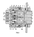
- the contact insert consists of several parts, 10a, 10b and 10c, of which the insert part 10c facing the cable entry has conical bores into which form-fitting, correspondingly shaped, frustoconical attachments of a rubber-elastic sealing washer 21 are introduced, which have a cylindrical bore for receiving the contact sockets 11.
- the connector housing is made in two parts and its two parts 7a and 7b can be screwed together by means of a thread so that liquid- or vapor-tight contact surfaces between the conical approaches of the sealing washer 21 and the contact insert part 10c as well as the cylindrical bore walls of the sealing washer 21 and the circumferential regions of the socket contacts 11 associated therewith arise.
- a sealing washer 21 it is also possible to use individual, non-interconnected, frustoconical sealing elements, each of which has a cylindrical bore for receiving the ends of the contact bushings 11 assigned to the cable entry.
- the invention creates a highly effective seal which is very easy to assemble and can also be used with only partially equipped plugs if a corresponding number of blind contact sockets, i.e. Contact sockets that are not connected to cable cores are inserted in the contact insert.
Abstract
Description
- Die vorliegende Erfindung betrifft einen Steckverbinder zum lösbaren Anschluß von Kabelleitungen entsprechend dem Oberbegriff des Hauptanspruches. Bekannte Steckverbinder dieser Art - beispielsweise die Rundsteckverbinder der Baureihe PT-SE der Fa.Teldix - erhalten als Feuchtigkeitsschutz im Bereich der Kabeleinführungen Dichtungseinsätze mit lamellenförmig ausgebildeten, an der Isolierung der einzelnen Kabeladern anliegenden Dichtungswülsten. Einerseits kann mit diesen Dichtungseinsätzen eine Längsdichtigkeit nur bei geringen Druckunterschieden zwischen der Umgebung und dem Inneren des Steckergehäuses erzielt werden, zum anderen bietet diese Dichtungsart prinzipiell keinen Schutz gegen durch die Kabelummantelung eingedrungendes Wasser bzw. dessen unkontrollierter Ausbreitung im Inneren des Steckergehäuses.
- Die Erfindung stellt sich die Aufgabe einen Steckverbinder der eingangs genannten Art auch bei extremen Umgebungsbedingungen, z.B. bei im Störfall in kerntechnischen Anlagen unter 6,5 bar austretendem Heißdampf, mit einer zuverlässigen Feuchtigkeits- bzw. Dampfsperre zu versehen. Gelöst wird diese Aufgabe erfindungsgemäß mit den im kennzeichnenden Teil des Hauptanspruches angegebenen Merkmalen.
- Die Erfindung samt ihren weiteren, in Unteransprüchen wiedergegebenen Ausgestaltungen soll nachstehend anhand der Figuren näher erläutert werden.
- Fig.l zeigt, teilweise aufgeschnitten, eine perspektivische Ansicht eines erfindungsgemäßen Steckverbinders und Fig. 2 einen dazugehörigen Längsteilschnitt. In die Wandung eines nicht näher dargestellten Gehäuses 1 ist die Steckdose 2 der Steckverbindung eingelassen und mittels eines Gewinderinges 3 befestigt. Zwischen Steckdose 2 und der Wandung des Gehäuses 1 ist eine 0-Ringdichtung 4 vorgesehen. Die Steckdose 2 weist in einen Isolierkörper 5 eingelassene Stecker 6 auf, von denen zwei in den Figuren "1 bzw. 2 dargestellt sind. In die Steckdose 2 ist ein im wesentlichen hohlzylinderförmiges Steckergehäuse 7 eingeschoben und mittels einer Überwurfmutter 8 fest mit ihr gekuppelt. Ein 0-Ring 9 ist zur Abdichtung zwischen Stekkergehäuse 7 und Steckdose 2 vorgesehen. Das Innere des Steckergehäuses 7 nimmt einen aus Isolierstoff bestehenden Kontakteinsatz 10 auf, in welchen auswechselbare Buchsenkontakte 11, mittels Federelemente 12 in der Gebrauchsstellung verrastbar, eingebracht sind. Ein Federring 13 sichert die Lage des Kontakteinsatzes 10 mit seiner eine zentrische Bohrung aufweisenden Stirnplatte 14. Die abisolierten Enden der Adern 15 eines durch eine Dichtverschraubung eingeführten Kabels 17 werden mittels einer Quetschverbindung jeweils mit einem der Buchsenkontakt 11 kontaktiert. Die anderen Enden des Buchsenkontaktes 11 weisen Bohrungen auf, welche die Steckerkontakte 6 der Steckdose 2 aufnehmen.
- Die Buchsenkontakte 11 weisen an ihren der Steckdose 2 abgewandten Enden Ringnuten 18 auf, welche zur Aufnahme von 0-Ringen 19 dienen, die im eingebauten Zustand unter elastischer Verformung an zugeordneten Wandungen des Kontakteinsatzes 10 anliegen und so eine sichere Abdichtung zwischen der Kabeleinführungsseite und der der Steckdose 2 zugekehrten Seite des Kontakteinsatzes 10 sicherstellen. Demselben Zweck dient ein weiterer 0-Ring 20, der in einer Ringnut des Steckergehäuses 7 gehaltert und nach dem Einbringen des Einsatzes 10 elastisch deformiert ist. Auf diese Weise wird sichergestellt, daß von der Kabeleinführungsseite - ganz gleich auf welchem Wege - in das Innere des Steckergehäuses 10 eingedrungene Feuchtigkeit nicht zu den steckdosenseitigen Kontakten 6 gelangen kann. Die 0-Ringe 19 und 20 bilden also im Inneren des Steckergehäuses 7 eine hochwirksame Feuchtigkeits- bzw. Dampfsperre in Längsrichtung, während außerhalb des Steckergehäuses 7 diese Funktion von dem 0-Ring 9 übernommen wird. Für die steckdosenseitigen Kontakte 6 wird daher selbst bei Überflutung des Steckverbinders ein absolut trockener Bereich geschaffen.
- Die Buchsenkontakte 11 sind in Bohrungen versenkt in den Kontakteinsatz 9 eingebracht. Dadurch können auf einfache Weise die im Hinblick auf die im "nassen" Bereich des Kontakteinsatzes 10 zu erwartende Feuchtigkeit erforderlichen Kriech- und Luftstrecken zwischen den Buchsenkontakten 11 geschaffen werden, während diese Strecken bei den sich im "trockenen" Bereich des Kontakteinsatzes 10 befindlichen Steckern 6 entsprechend normalen Umgebungsbedingungen bemessen werden können.
- Fig.3 zeigt eine zweite Variante der Erfindung, wobei für gleichwirkende Elemente dieselben Bezugszeichen wie bei den figuren 1 und 2 verwendet sind. Zum Unterschied zu der in den Figuren 1 und 2 dargestellten Ausführungsform besteht der Kontakteinsatz aus mehreren Teilen, 10a, 10b und 10c, wovon der der Kabeleinführung zugewandte Einsatzteil 10c kegelige Bohrungen aufweist, in welche formschlüssig entsprechend geformte kegelstumpfförmige Aufsätze einer gummielastischen Dichtscheibe 21 eingebracht sind, welche eine zylindriche Bohrung zur Aufnahme der Kontaktbuchsen 11 aufweisen. Das Steckergehäuse ist zweiteilig ausgeführt und dessen beide Teile 7a und 7b können mittels eines Gewindes soweit zusammengeschraubt werden, daß flüssigkeits- bzw. dampfdichte Berührungsflächen zwischen den kegeligen Ansätzen der Dichtscheibe 21 und dem Kontakteinsatzteil 10c sowie den zylindrischen Bohrungswandungen der Dichtscheibe 21 und den diesen zugeordneten Umfangsbereichen der Buchsenkontakte 11 entstehen. Anstelle einer Dichtscheibe 21 können auch einzelne, nicht miteinander verbundene, kegelstumpfförmig ausgebildete Dichtelemente verwendet werden, welche jeweils eine zylindrische Bohrung zur Aufnahme der der Kabeleinführung zugeordneten Enden der Kontaktbuchsen 11 aufweisen.
- Insgesamt wird durch die Erfindung eine hochwirksame Abdichtung geschaffen, welche sehr montagefreundlich ist und ohne weiteres auch bei nur teilbestückten Steckern verwendbar ist, wenn eine entsprechende Anzahl von Blindkontaktbuchsen, d.h. nicht mit Kabeladern verbundene Kontaktbuchsen in den Kontakteinsatz eingebracht werden.
Claims (8)
Priority Applications (1)
| Application Number | Priority Date | Filing Date | Title |
|---|---|---|---|
| AT84109253T ATE31231T1 (de) | 1983-08-16 | 1984-08-03 | Steckverbinder zum loesbaren anschluss von kabelleitungen. |
Applications Claiming Priority (2)
| Application Number | Priority Date | Filing Date | Title |
|---|---|---|---|
| DE3329580 | 1983-08-16 | ||
| DE3329580A DE3329580A1 (de) | 1983-08-16 | 1983-08-16 | Steckverbinder zum loesbaren anschluss von kabelleitungen |
Publications (2)
| Publication Number | Publication Date |
|---|---|
| EP0134542A1 true EP0134542A1 (de) | 1985-03-20 |
| EP0134542B1 EP0134542B1 (de) | 1987-12-02 |
Family
ID=6206687
Family Applications (1)
| Application Number | Title | Priority Date | Filing Date |
|---|---|---|---|
| EP84109253A Expired EP0134542B1 (de) | 1983-08-16 | 1984-08-03 | Steckverbinder zum lösbaren Anschluss von Kabelleitungen |
Country Status (3)
| Country | Link |
|---|---|
| EP (1) | EP0134542B1 (de) |
| AT (1) | ATE31231T1 (de) |
| DE (2) | DE3329580A1 (de) |
Cited By (12)
| Publication number | Priority date | Publication date | Assignee | Title |
|---|---|---|---|---|
| EP0300804A2 (de) * | 1987-07-24 | 1989-01-25 | Honda Giken Kogyo Kabushiki Kaisha | Wasserdichter Verbinder |
| EP0715374A3 (de) * | 1994-11-28 | 1997-04-23 | Ford Motor Co | Trennbarer Verbinder für ein automatisches Kraftfahrzeuggetriebe |
| EP0844698A2 (de) * | 1996-11-22 | 1998-05-27 | Sumitomo Wiring Systems, Ltd. | Montagestruktur für Verbindergehäuse |
| EP1608043A1 (de) * | 2004-06-18 | 2005-12-21 | ERICH JAEGER GmbH & Co. KG | Steckeinheit für eine mehrpolige Steckverbindung |
| WO2011076399A1 (de) * | 2009-12-23 | 2011-06-30 | Oase Gmbh | Steckerverbindungsanordnung für feuchtigkeitsgeschützte elektrische steckverbindung |
| CN103138103A (zh) * | 2013-03-20 | 2013-06-05 | 苏州瑞可达连接系统有限公司 | 一种线缆接头 |
| DE102012218401A1 (de) * | 2012-10-10 | 2014-04-24 | Schaeffler Technologies Gmbh & Co. Kg | Steckerverbindung mit Dichtelementen |
| WO2014180938A1 (de) * | 2013-05-10 | 2014-11-13 | Phoenix Contact Gmbh & Co. Kg | Wasserdichte elektrische verbinder |
| ITMI20131357A1 (it) * | 2013-08-07 | 2015-02-08 | Palazzoli Spa | Connettore elettrico |
| CN105790020A (zh) * | 2016-03-09 | 2016-07-20 | 东莞市尖峰电子科技有限公司 | 一种具有密封能力的电缆连接头 |
| CN106785646A (zh) * | 2016-12-15 | 2017-05-31 | 中国船舶重工集团公司第七0五研究所 | 一种穿舱电缆的耐压密封结构 |
| CN110088983A (zh) * | 2016-11-14 | 2019-08-02 | 安费诺有限公司 | 连接器端子及组装该连接器端子的方法 |
Families Citing this family (3)
| Publication number | Priority date | Publication date | Assignee | Title |
|---|---|---|---|---|
| DE3918548A1 (de) * | 1989-06-07 | 1990-12-13 | Dietrich Gebhard | Steckdose fuer eine steckverbindung fuer den elektrischen anschluss von kraftfahrzeuganhaengern |
| DE102006037355B3 (de) * | 2006-08-09 | 2008-01-03 | Areva Np Gmbh | Multipol-Kabelverbindung sowie Brennelement-Lademaschine |
| DE102012005326A1 (de) * | 2012-03-19 | 2013-10-02 | Detlef Gödicke | Rundsteckverbinder für Midi-Verbindungen |
Citations (4)
| Publication number | Priority date | Publication date | Assignee | Title |
|---|---|---|---|---|
| GB725021A (en) * | 1952-05-07 | 1955-03-02 | Titeflex Inc | Shielded waterproof electrical plug and socket connectors |
| GB1116143A (en) * | 1964-06-15 | 1968-06-06 | Amphenol Corp | Improvements in or relating to electrical connectors |
| US3816641A (en) * | 1973-05-14 | 1974-06-11 | Viking Industries | Underwater connector and method of making same |
| US4355855A (en) * | 1979-02-07 | 1982-10-26 | Dimitri Rebikoff | Deep water connector |
-
1983
- 1983-08-16 DE DE3329580A patent/DE3329580A1/de not_active Withdrawn
-
1984
- 1984-08-03 EP EP84109253A patent/EP0134542B1/de not_active Expired
- 1984-08-03 DE DE8484109253T patent/DE3467958D1/de not_active Expired
- 1984-08-03 AT AT84109253T patent/ATE31231T1/de not_active IP Right Cessation
Patent Citations (4)
| Publication number | Priority date | Publication date | Assignee | Title |
|---|---|---|---|---|
| GB725021A (en) * | 1952-05-07 | 1955-03-02 | Titeflex Inc | Shielded waterproof electrical plug and socket connectors |
| GB1116143A (en) * | 1964-06-15 | 1968-06-06 | Amphenol Corp | Improvements in or relating to electrical connectors |
| US3816641A (en) * | 1973-05-14 | 1974-06-11 | Viking Industries | Underwater connector and method of making same |
| US4355855A (en) * | 1979-02-07 | 1982-10-26 | Dimitri Rebikoff | Deep water connector |
Cited By (23)
| Publication number | Priority date | Publication date | Assignee | Title |
|---|---|---|---|---|
| EP0300804A2 (de) * | 1987-07-24 | 1989-01-25 | Honda Giken Kogyo Kabushiki Kaisha | Wasserdichter Verbinder |
| EP0300804A3 (en) * | 1987-07-24 | 1990-04-11 | Honda Giken Kogyo Kabushiki Kaisha | Water-proof connector |
| EP0715374A3 (de) * | 1994-11-28 | 1997-04-23 | Ford Motor Co | Trennbarer Verbinder für ein automatisches Kraftfahrzeuggetriebe |
| EP0844698A2 (de) * | 1996-11-22 | 1998-05-27 | Sumitomo Wiring Systems, Ltd. | Montagestruktur für Verbindergehäuse |
| EP0844698A3 (de) * | 1996-11-22 | 1999-03-03 | Sumitomo Wiring Systems, Ltd. | Montagestruktur für Verbindergehäuse |
| EP1608043A1 (de) * | 2004-06-18 | 2005-12-21 | ERICH JAEGER GmbH & Co. KG | Steckeinheit für eine mehrpolige Steckverbindung |
| US8747138B2 (en) | 2009-12-23 | 2014-06-10 | Oase Gmbh | Plug connection assembly for a moisture-protected electrical plug connection |
| WO2011076399A1 (de) * | 2009-12-23 | 2011-06-30 | Oase Gmbh | Steckerverbindungsanordnung für feuchtigkeitsgeschützte elektrische steckverbindung |
| CN102714371B (zh) * | 2009-12-23 | 2016-01-20 | 欧亚瑟有限公司 | 用于防水电接插件的插头连接组件 |
| CN102714371A (zh) * | 2009-12-23 | 2012-10-03 | 欧亚瑟有限公司 | 用于防水电接插件的插头连接组件 |
| DE102012218401A1 (de) * | 2012-10-10 | 2014-04-24 | Schaeffler Technologies Gmbh & Co. Kg | Steckerverbindung mit Dichtelementen |
| CN103138103A (zh) * | 2013-03-20 | 2013-06-05 | 苏州瑞可达连接系统有限公司 | 一种线缆接头 |
| WO2014180938A1 (de) * | 2013-05-10 | 2014-11-13 | Phoenix Contact Gmbh & Co. Kg | Wasserdichte elektrische verbinder |
| ITMI20131357A1 (it) * | 2013-08-07 | 2015-02-08 | Palazzoli Spa | Connettore elettrico |
| CN105790020B (zh) * | 2016-03-09 | 2018-06-19 | 东莞市尖峰电子科技有限公司 | 一种具有密封能力的电缆连接头 |
| CN105790020A (zh) * | 2016-03-09 | 2016-07-20 | 东莞市尖峰电子科技有限公司 | 一种具有密封能力的电缆连接头 |
| KR20190091279A (ko) * | 2016-11-14 | 2019-08-05 | 암페놀 코포레이션 | 커넥터 단자 및 그것의 조립 방법 |
| CN110088983A (zh) * | 2016-11-14 | 2019-08-02 | 安费诺有限公司 | 连接器端子及组装该连接器端子的方法 |
| EP3539184A4 (de) * | 2016-11-14 | 2020-06-10 | Amphenol Corporation | Anschlussklemme und verfahren zur anordnung davon |
| CN110088983B (zh) * | 2016-11-14 | 2021-07-30 | 安费诺有限公司 | 连接器端子及组装该连接器端子的方法 |
| CN113659384A (zh) * | 2016-11-14 | 2021-11-16 | 安费诺有限公司 | 连接器端子及组装该连接器端子的方法 |
| CN106785646B (zh) * | 2016-12-15 | 2018-11-09 | 中国船舶重工集团公司第七0五研究所 | 一种穿舱电缆的耐压密封结构 |
| CN106785646A (zh) * | 2016-12-15 | 2017-05-31 | 中国船舶重工集团公司第七0五研究所 | 一种穿舱电缆的耐压密封结构 |
Also Published As
| Publication number | Publication date |
|---|---|
| DE3467958D1 (en) | 1988-01-14 |
| ATE31231T1 (de) | 1987-12-15 |
| DE3329580A1 (de) | 1985-03-07 |
| EP0134542B1 (de) | 1987-12-02 |
Similar Documents
| Publication | Publication Date | Title |
|---|---|---|
| EP0134542A1 (de) | Steckverbinder zum lösbaren Anschluss von Kabelleitungen | |
| DE69838642T2 (de) | Sicherungsträger und verbinder | |
| EP0886156B1 (de) | Einrichtung zur Zugentlastung elektrischer und/oder optischer Leiter eines Kabels | |
| DE2313726C3 (de) | Steckvorrichtung mit einem Stecker und einer Kupplung | |
| DE3318248A1 (de) | Mehrpoliger elektrischer stecker, insbesondere rundstecker | |
| EP1867024B1 (de) | Leitungsdurchführungsvorrichtung | |
| DE2927438A1 (de) | Elektrischer steckverbinder | |
| DE2550245A1 (de) | Anschlussklemme fuer eine vorrichtung oder ein element zur elektrischen verbindung | |
| DE2123053C3 (de) | Anordnung zum Zuführen eines geschirmten mehradrigen Kabels | |
| EP0949711A2 (de) | Kabelsteckverbinder | |
| DE8125854U1 (de) | Als elektrischer Stecker oder als Steckdose oder als Kupplungsdose ausgebildetes Installationsteil | |
| EP0444478A1 (de) | Kontaktträger für eine Steckdose oder einen Stecker für eine Steckverbindungen fÀ¼r den elektrischen Anschluss von Kraftfahrzeuganhängern | |
| DE2824507C2 (de) | Steckvorrichtung zur elektromagnetischen Kopplung von optischen Faserleitern | |
| DE3005337A1 (de) | Elektrischer steckverbinder | |
| DE2409311A1 (de) | Steckdose | |
| DE19525801C2 (de) | Vorrichtung zum elektrisch leitenden Verbinden von zwei elektrischen Leitungen | |
| DE19844829A1 (de) | Elektrischer Steckverbinder und Erdungselement | |
| EP1263089B1 (de) | Kabelverbindungsvorrichtung | |
| DE3508329A1 (de) | Steckbare kabelgarnitur | |
| DE3538193C2 (de) | ||
| DE3908532C2 (de) | ||
| DE2606917C3 (de) | Elektrischer Koaxialsteckverbinder | |
| DE3033104C2 (de) | Vorrichtung zum Anschließen eines elektrischen Leiters an eine isolierte Freileitung | |
| EP0359939A2 (de) | Luftfeder mit einer Vorrichtung zur Leitungsverbindung | |
| DE3011762C2 (de) | Mehrpolige Kragensteckvorrichtung |
Legal Events
| Date | Code | Title | Description |
|---|---|---|---|
| PUAI | Public reference made under article 153(3) epc to a published international application that has entered the european phase |
Free format text: ORIGINAL CODE: 0009012 |
|
| AK | Designated contracting states |
Designated state(s): AT BE DE FR GB |
|
| 17P | Request for examination filed |
Effective date: 19850426 |
|
| GRAA | (expected) grant |
Free format text: ORIGINAL CODE: 0009210 |
|
| AK | Designated contracting states |
Kind code of ref document: B1 Designated state(s): AT BE DE FR GB |
|
| REF | Corresponds to: |
Ref document number: 31231 Country of ref document: AT Date of ref document: 19871215 Kind code of ref document: T |
|
| REF | Corresponds to: |
Ref document number: 3467958 Country of ref document: DE Date of ref document: 19880114 |
|
| ET | Fr: translation filed | ||
| GBT | Gb: translation of ep patent filed (gb section 77(6)(a)/1977) | ||
| PLBE | No opposition filed within time limit |
Free format text: ORIGINAL CODE: 0009261 |
|
| STAA | Information on the status of an ep patent application or granted ep patent |
Free format text: STATUS: NO OPPOSITION FILED WITHIN TIME LIMIT |
|
| 26N | No opposition filed | ||
| PGFP | Annual fee paid to national office [announced via postgrant information from national office to epo] |
Ref country code: GB Payment date: 19890731 Year of fee payment: 6 |
|
| PGFP | Annual fee paid to national office [announced via postgrant information from national office to epo] |
Ref country code: AT Payment date: 19890803 Year of fee payment: 6 |
|
| PGFP | Annual fee paid to national office [announced via postgrant information from national office to epo] |
Ref country code: BE Payment date: 19890824 Year of fee payment: 6 |
|
| PGFP | Annual fee paid to national office [announced via postgrant information from national office to epo] |
Ref country code: FR Payment date: 19890825 Year of fee payment: 6 |
|
| PGFP | Annual fee paid to national office [announced via postgrant information from national office to epo] |
Ref country code: DE Payment date: 19891026 Year of fee payment: 6 |
|
| PG25 | Lapsed in a contracting state [announced via postgrant information from national office to epo] |
Ref country code: GB Effective date: 19900803 Ref country code: AT Effective date: 19900803 |
|
| PG25 | Lapsed in a contracting state [announced via postgrant information from national office to epo] |
Ref country code: BE Effective date: 19900831 |
|
| BERE | Be: lapsed |
Owner name: SIEMENS A.G. BERLIN UND MUNCHEN Effective date: 19900831 |
|
| GBPC | Gb: european patent ceased through non-payment of renewal fee | ||
| PG25 | Lapsed in a contracting state [announced via postgrant information from national office to epo] |
Ref country code: FR Effective date: 19910430 |
|
| PG25 | Lapsed in a contracting state [announced via postgrant information from national office to epo] |
Ref country code: DE Effective date: 19910501 |
|
| REG | Reference to a national code |
Ref country code: FR Ref legal event code: ST |