EP0133617A2 - Armature pour constructions en béton armé - Google Patents
Armature pour constructions en béton armé Download PDFInfo
- Publication number
- EP0133617A2 EP0133617A2 EP84890147A EP84890147A EP0133617A2 EP 0133617 A2 EP0133617 A2 EP 0133617A2 EP 84890147 A EP84890147 A EP 84890147A EP 84890147 A EP84890147 A EP 84890147A EP 0133617 A2 EP0133617 A2 EP 0133617A2
- Authority
- EP
- European Patent Office
- Prior art keywords
- reinforcement
- bracket
- elements
- recess
- die
- Prior art date
- Legal status (The legal status is an assumption and is not a legal conclusion. Google has not performed a legal analysis and makes no representation as to the accuracy of the status listed.)
- Granted
Links
Images


Classifications
-
- E—FIXED CONSTRUCTIONS
- E04—BUILDING
- E04C—STRUCTURAL ELEMENTS; BUILDING MATERIALS
- E04C5/00—Reinforcing elements, e.g. for concrete; Auxiliary elements therefor
- E04C5/01—Reinforcing elements of metal, e.g. with non-structural coatings
- E04C5/06—Reinforcing elements of metal, e.g. with non-structural coatings of high bending resistance, i.e. of essentially three-dimensional extent, e.g. lattice girders
- E04C5/0604—Prismatic or cylindrical reinforcement cages composed of longitudinal bars and open or closed stirrup rods
- E04C5/0609—Closed cages composed of two or more coacting cage parts, e.g. transversally hinged or nested parts
Definitions
- the invention relates to a reinforcement for reinforced concrete structures, which the parts to be installed or recesses interrupting the reinforcement, such as e.g. Joint tapes or connection recesses on precast structures, surrounded and forms a replacement of the interrupted reinforcement.
- the invention has for its object to provide a reinforcement of the type mentioned, which requires fewer parts and shorter installation times, can be produced mechanically in the factory as a batch and can be easily installed at the construction site.
- the reinforcement designed according to the invention in that it consists of egg Nem pair of reinforcement elements, each of which has at least one Z-shaped curved bracket, and that these two elements are arranged in a mirror-inverted manner, so that between the central parts of the bracket the part to be installed or the recess and the leg of the recess associated with the leg of the Form a closed cage reinforcement in the area of the crack zones.
- two mutually identical reinforcement elements with brackets in Z-Fozm are thus provided, which are opposite, ie. H. in mirror image, with mutually parallel central parts, arranged in the desired distance adapted to the recess, overlapping their legs lying in the replacement zone.
- This allows you to adapt to varying wall thicknesses and widths of the built-in part, such as a joint tape, or the recess to be provided in wide areas, u. each with a pair of elements designed in this way.
- a special embodiment of the invention is that several brackets are connected to one element by holding rods, preferably by welding. Such elements can be easily prefabricated in the factory and easily stacked.
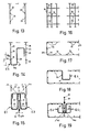
- a previous joint tape guard consists of two U-brackets 1 which are arranged next to one another while leaving a distance, and a further bracket 2 which extends between the outer legs of the bracket 1.
- the encirclement consisting of these three brackets 1, 2 is fastened to the vertical support rods 3 in a conventional manner.
- the vertical joint tape 4 is arranged between the inner legs of the bracket 1, normal to the plane of exchange, and is connected by means of the clamps 5, which comprise both ends of the joint tape 4, to the bars 3 with wires 6 and thereby tensioned.
- the bracket 2 prevents cracking in the areas of zones A and B after the concrete has been poured.
- FIGS. 3 and 4 A corresponding procedure has been followed in the manufacture of a barrier for the horizontal joint tape of a foundation plate with a rising wall, as can be seen from FIGS. 3 and 4.
- the rod 7 has to perform the function of the bracket 2 in Fig. 2; it bridges, held on longitudinal rods 8, the ends of the transverse rods 10 and 11 which are precisely bent with respect to their spacing and which are connected by the longitudinal rods 12, 13, and 14.
- the joint tape 16 lying at the base of the wall is arranged normal to the replacement plane, and the crack zones A, B are reinforced by this type of replacement.
- the reinforcement element E1 and E2 consists of a series of Z-brackets 17 and 19, each in a curved Z-shape, with an upper leg 17b, 19b with the bracket middle parts 17a, 19a Length X2 and at the end a downward curve 17c, 19c with of length Y2 and a lower leg 17d, 19d and at the end an upward bend 17e, 19e with length Y1 are provided.
- This row of Z brackets 17, 19, which have the same distance X8, is connected to one another by two holding rods 18, 20 (FIG. 9).
- the outer holding rod 18, 20 is arranged on the bend 17c, 19c of the upper leg 17b, 19b of the bracket 17, 19, approximately in the middle thereof, and the inner holding rod 18, 20 is on the middle part 17a, 19a of the bracket 17, 19 arranged around its upper quarter point.
- the rods 18, 20 are with the brackets 17, 19, z. B. connected by welding.
- the holding rods 18, 20 do not hinder the pushing together of the elements E1, E2 described below.
- the holding rods 18, 20 must therefore lie above the ends of the legs 17e, 19e.
- the middle parts 17a, 19a of the brackets 17, 19 lie at a distance X1 from one another and the upper and lower bends 17c, 17e and 19c, 19e are exactly one above the other.
- the length X2 of the upper leg 17b, 19b corresponds to the distance between the middle part 17a of one bracket 17 and the bends 19e of the other bracket 19, and vice versa. 7 for a minimum wall thickness of X1 + 2.
- X2 X3 suitable.
- the element E3 according to FIGS. 10 to 12 differs from those according to FIG. 5 in that the upper leg 21b of the Z-bracket 21 with the length X9 is not bent over, but rather protrudes from the bracket middle part 21a.
- the lower leg 21c with the bend 21d has the length X10 (FIG. 10).
- the brackets 21 are connected to one another by holding rods 22 at a distance X11 (FIG. 11). This results in z. B. a barrier according to FIG. 12, in which the middle parts 21a of the bracket 21 are at a distance X12 and the crack zones 24, 25 are covered again.
- Figs. 13 to 15 illustrate the assembly of the reinforcement elements E1 according to the invention, E2 in an application according to Fig. 2.
- 13 F ig. In consisting of transverse rods 25 and longitudinal rods existing 26 supporting reinforcement of a wall first of the one element E1, which is similar 6, but has a bend 19e with the length Y3 on the lower leg 19d of the bracket 19 (FIG. 14), and then the other element E2 is inserted (FIG. 15) and connected to the bars 25, 26, e.g. B. by binding with wire. Anticipate the supporting rods have been inserted 28 in order to be able to connect to the assembly of the elements E1, E2 at the corners (FIG. 15).
- the rods 27 must be inserted and fixed in the direction of the arrow P f.4. Thereupon, the F is ugenband 29 in the remainder of the recess, used on the wires 30 held in clamps 31 and tensioned.
- the crack zones 32 are so well secured by this cage reinforcement.
- FIG. 16 to 19 accordingly illustrate the installation of a reinforcement made of elements E4 in a foundation plate in the application according to FIG. 4.
- the foundation plate reinforcement (FIG. 16, 17) formed from the transverse bars 33, 35 and the longitudinal bars 34
- an element first becomes E4, similar to FIG. 10, inserted with brackets 21 and holding rods 22 and connected to the foundation reinforcement (FIG. 18), and then the second element E4 is introduced (FIG. 19).
- the upper rods 36 must be inserted in advance, and finally the joint tape 39 is tensioned with the wires 37, which are components of the clamps 38.
- both legs of the Z-bracket adjoining the central part can also be straight.
- the arrangement of the holding rods 18, 20 can also take place at a location other than that shown if they only allow the pair of elements to be fitted into one another.
Landscapes
- Engineering & Computer Science (AREA)
- Architecture (AREA)
- Civil Engineering (AREA)
- Structural Engineering (AREA)
- Rod-Shaped Construction Members (AREA)
- Reinforcement Elements For Buildings (AREA)
- Working Measures On Existing Buildindgs (AREA)
- Curing Cements, Concrete, And Artificial Stone (AREA)
Applications Claiming Priority (2)
| Application Number | Priority Date | Filing Date | Title |
|---|---|---|---|
| AT2893/83 | 1983-08-10 | ||
| AT0289383A AT378981B (de) | 1983-08-10 | 1983-08-10 | Bewehrung fuer stahlbetonkonstruktionen |
Publications (3)
| Publication Number | Publication Date |
|---|---|
| EP0133617A2 true EP0133617A2 (fr) | 1985-02-27 |
| EP0133617A3 EP0133617A3 (en) | 1987-01-07 |
| EP0133617B1 EP0133617B1 (fr) | 1990-05-02 |
Family
ID=3541970
Family Applications (1)
| Application Number | Title | Priority Date | Filing Date |
|---|---|---|---|
| EP84890147A Expired - Lifetime EP0133617B1 (fr) | 1983-08-10 | 1984-08-01 | Armature pour constructions en béton armé |
Country Status (3)
| Country | Link |
|---|---|
| EP (1) | EP0133617B1 (fr) |
| AT (2) | AT378981B (fr) |
| DE (1) | DE3482127D1 (fr) |
Cited By (1)
| Publication number | Priority date | Publication date | Assignee | Title |
|---|---|---|---|---|
| GB2205596A (en) * | 1987-06-03 | 1988-12-14 | George Cyril Brown | A method of jointing concrete floor slabs |
Citations (4)
| Publication number | Priority date | Publication date | Assignee | Title |
|---|---|---|---|---|
| DE636104C (de) * | 1934-01-30 | 1936-10-05 | Paul Kroker | Eisenbetonbalken-Bewehrungseinlage mit diese im Abstand von der Schalung haltenden Stuetzgliedern |
| DE2122851A1 (de) * | 1970-05-12 | 1971-12-02 | Oroschakoff, Georgi, Dipl.-Ing., Wien | Bewehrung für Stahlbetonkonstruktionen |
| US4132045A (en) * | 1977-10-27 | 1979-01-02 | The Dayton Sure-Grip & Shore Company | Reinforcing bar support |
| DE8208261U1 (de) * | 1982-03-23 | 1982-12-30 | Drahtwerke Fischer AG, 5734 Reinach | Anschlusskorb zum armieren von eisenbetonkonstruktionen und dessen verwendung |
-
1983
- 1983-08-10 AT AT0289383A patent/AT378981B/de not_active IP Right Cessation
-
1984
- 1984-08-01 AT AT84890147T patent/ATE53886T1/de active
- 1984-08-01 EP EP84890147A patent/EP0133617B1/fr not_active Expired - Lifetime
- 1984-08-01 DE DE8484890147T patent/DE3482127D1/de not_active Expired - Fee Related
Patent Citations (4)
| Publication number | Priority date | Publication date | Assignee | Title |
|---|---|---|---|---|
| DE636104C (de) * | 1934-01-30 | 1936-10-05 | Paul Kroker | Eisenbetonbalken-Bewehrungseinlage mit diese im Abstand von der Schalung haltenden Stuetzgliedern |
| DE2122851A1 (de) * | 1970-05-12 | 1971-12-02 | Oroschakoff, Georgi, Dipl.-Ing., Wien | Bewehrung für Stahlbetonkonstruktionen |
| US4132045A (en) * | 1977-10-27 | 1979-01-02 | The Dayton Sure-Grip & Shore Company | Reinforcing bar support |
| DE8208261U1 (de) * | 1982-03-23 | 1982-12-30 | Drahtwerke Fischer AG, 5734 Reinach | Anschlusskorb zum armieren von eisenbetonkonstruktionen und dessen verwendung |
Cited By (2)
| Publication number | Priority date | Publication date | Assignee | Title |
|---|---|---|---|---|
| GB2205596A (en) * | 1987-06-03 | 1988-12-14 | George Cyril Brown | A method of jointing concrete floor slabs |
| GB2205596B (en) * | 1987-06-03 | 1991-04-17 | George Cyril Brown | A method of jointing concrete floor slabs |
Also Published As
| Publication number | Publication date |
|---|---|
| ATE53886T1 (de) | 1990-06-15 |
| DE3482127D1 (de) | 1990-06-07 |
| EP0133617B1 (fr) | 1990-05-02 |
| ATA289383A (de) | 1985-03-15 |
| EP0133617A3 (en) | 1987-01-07 |
| AT378981B (de) | 1985-10-25 |
Similar Documents
| Publication | Publication Date | Title |
|---|---|---|
| DE2122851A1 (de) | Bewehrung für Stahlbetonkonstruktionen | |
| DE2058638A1 (de) | Bewehrung fuer Stahlbetonkonstruktionen | |
| EP0299226B1 (fr) | Coffrage pour la réalisation d'éléments de construction en béton | |
| DE2412381B2 (de) | Befestigungsanordnung für Begrenzungstafeln in Form eines Gitters | |
| DE2931563A1 (de) | Abstandhalter | |
| DE19640652A1 (de) | Bauelement zur Wärmedämmung | |
| EP0133617B1 (fr) | Armature pour constructions en béton armé | |
| EP2137353A1 (fr) | Élément de coffrage | |
| EP0143101A2 (fr) | Armature pour constructions de béton armé | |
| EP0542116B1 (fr) | Elément de coffrage perdu | |
| CH698206B1 (de) | Anschlusskorb für vorfabrizierte Doppelwandelemente. | |
| DE60007824T2 (de) | Gitterträger | |
| EP0465777A1 (fr) | Poutre en treillis | |
| AT390103B (de) | Anschlussbewehrung fuer stahlbetonkonstruktionen | |
| DE19722028A1 (de) | Bauelement zur Wärmedämmung | |
| AT406281B (de) | Stahlbetonbewehrung | |
| EP2175079B1 (fr) | Procédé de formation d'une armature d'angle résistante à la flexion pour la construction en béton armé, élément d'armature et armature d'angle résistante à la flexion | |
| WO1997018374A1 (fr) | Unite prefabriquee pour fenetre | |
| AT378216B (de) | Bewehrungsmatte fuer stahlbeton | |
| AT378978B (de) | Bewehrung fuer stahlbetonkonstruktionen | |
| DE1931210C (de) | Hangedecke | |
| DE8002299U1 (de) | Wandelement in fertigbauweise | |
| DE3210664A1 (de) | Abstands- und streckelement zur verwendung bei vorgefertigten bauelementen | |
| DE1658884C (de) | Gebäude aus Säulen und vorgefertigten Deckenplatten | |
| AT360214B (de) | Bewehrungsmatte |
Legal Events
| Date | Code | Title | Description |
|---|---|---|---|
| PUAI | Public reference made under article 153(3) epc to a published international application that has entered the european phase |
Free format text: ORIGINAL CODE: 0009012 |
|
| AK | Designated contracting states |
Designated state(s): AT CH DE FR GB IT LI NL |
|
| PUAL | Search report despatched |
Free format text: ORIGINAL CODE: 0009013 |
|
| AK | Designated contracting states |
Kind code of ref document: A3 Designated state(s): AT CH DE FR GB IT LI NL |
|
| 17P | Request for examination filed |
Effective date: 19870629 |
|
| 17Q | First examination report despatched |
Effective date: 19881212 |
|
| GRAA | (expected) grant |
Free format text: ORIGINAL CODE: 0009210 |
|
| AK | Designated contracting states |
Kind code of ref document: B1 Designated state(s): AT CH DE FR GB IT LI NL |
|
| PG25 | Lapsed in a contracting state [announced via postgrant information from national office to epo] |
Ref country code: NL Effective date: 19900502 Ref country code: IT Free format text: LAPSE BECAUSE OF FAILURE TO SUBMIT A TRANSLATION OF THE DESCRIPTION OR TO PAY THE FEE WITHIN THE PRESCRIBED TIME-LIMIT;WARNING: LAPSES OF ITALIAN PATENTS WITH EFFECTIVE DATE BEFORE 2007 MAY HAVE OCCURRED AT ANY TIME BEFORE 2007. THE CORRECT EFFECTIVE DATE MAY BE DIFFERENT FROM THE ONE RECORDED. Effective date: 19900502 Ref country code: GB Effective date: 19900502 Ref country code: FR Effective date: 19900502 |
|
| REF | Corresponds to: |
Ref document number: 53886 Country of ref document: AT Date of ref document: 19900615 Kind code of ref document: T |
|
| REF | Corresponds to: |
Ref document number: 3482127 Country of ref document: DE Date of ref document: 19900607 |
|
| PG25 | Lapsed in a contracting state [announced via postgrant information from national office to epo] |
Ref country code: AT Effective date: 19900801 |
|
| PG25 | Lapsed in a contracting state [announced via postgrant information from national office to epo] |
Ref country code: LI Effective date: 19900831 Ref country code: CH Effective date: 19900831 |
|
| EN | Fr: translation not filed | ||
| NLV1 | Nl: lapsed or annulled due to failure to fulfill the requirements of art. 29p and 29m of the patents act | ||
| GBV | Gb: ep patent (uk) treated as always having been void in accordance with gb section 77(7)/1977 [no translation filed] | ||
| PLBE | No opposition filed within time limit |
Free format text: ORIGINAL CODE: 0009261 |
|
| STAA | Information on the status of an ep patent application or granted ep patent |
Free format text: STATUS: NO OPPOSITION FILED WITHIN TIME LIMIT |
|
| 26N | No opposition filed | ||
| REG | Reference to a national code |
Ref country code: CH Ref legal event code: PL |
|
| PGFP | Annual fee paid to national office [announced via postgrant information from national office to epo] |
Ref country code: DE Payment date: 19981020 Year of fee payment: 15 |
|
| PG25 | Lapsed in a contracting state [announced via postgrant information from national office to epo] |
Ref country code: DE Free format text: LAPSE BECAUSE OF NON-PAYMENT OF DUE FEES Effective date: 20000601 |