EP0133617A2 - Reinforcement for armoured concrete constructions - Google Patents
Reinforcement for armoured concrete constructions Download PDFInfo
- Publication number
- EP0133617A2 EP0133617A2 EP84890147A EP84890147A EP0133617A2 EP 0133617 A2 EP0133617 A2 EP 0133617A2 EP 84890147 A EP84890147 A EP 84890147A EP 84890147 A EP84890147 A EP 84890147A EP 0133617 A2 EP0133617 A2 EP 0133617A2
- Authority
- EP
- European Patent Office
- Prior art keywords
- reinforcement
- bracket
- elements
- recess
- die
- Prior art date
- Legal status (The legal status is an assumption and is not a legal conclusion. Google has not performed a legal analysis and makes no representation as to the accuracy of the status listed.)
- Granted
Links
Images


Classifications
-
- E—FIXED CONSTRUCTIONS
- E04—BUILDING
- E04C—STRUCTURAL ELEMENTS; BUILDING MATERIALS
- E04C5/00—Reinforcing elements, e.g. for concrete; Auxiliary elements therefor
- E04C5/01—Reinforcing elements of metal, e.g. with non-structural coatings
- E04C5/06—Reinforcing elements of metal, e.g. with non-structural coatings of high bending resistance, i.e. of essentially three-dimensional extent, e.g. lattice girders
- E04C5/0604—Prismatic or cylindrical reinforcement cages composed of longitudinal bars and open or closed stirrup rods
- E04C5/0609—Closed cages composed of two or more coacting cage parts, e.g. transversally hinged or nested parts
Definitions
- the invention relates to a reinforcement for reinforced concrete structures, which the parts to be installed or recesses interrupting the reinforcement, such as e.g. Joint tapes or connection recesses on precast structures, surrounded and forms a replacement of the interrupted reinforcement.
- the invention has for its object to provide a reinforcement of the type mentioned, which requires fewer parts and shorter installation times, can be produced mechanically in the factory as a batch and can be easily installed at the construction site.
- the reinforcement designed according to the invention in that it consists of egg Nem pair of reinforcement elements, each of which has at least one Z-shaped curved bracket, and that these two elements are arranged in a mirror-inverted manner, so that between the central parts of the bracket the part to be installed or the recess and the leg of the recess associated with the leg of the Form a closed cage reinforcement in the area of the crack zones.
- two mutually identical reinforcement elements with brackets in Z-Fozm are thus provided, which are opposite, ie. H. in mirror image, with mutually parallel central parts, arranged in the desired distance adapted to the recess, overlapping their legs lying in the replacement zone.
- This allows you to adapt to varying wall thicknesses and widths of the built-in part, such as a joint tape, or the recess to be provided in wide areas, u. each with a pair of elements designed in this way.
- a special embodiment of the invention is that several brackets are connected to one element by holding rods, preferably by welding. Such elements can be easily prefabricated in the factory and easily stacked.
- a previous joint tape guard consists of two U-brackets 1 which are arranged next to one another while leaving a distance, and a further bracket 2 which extends between the outer legs of the bracket 1.
- the encirclement consisting of these three brackets 1, 2 is fastened to the vertical support rods 3 in a conventional manner.
- the vertical joint tape 4 is arranged between the inner legs of the bracket 1, normal to the plane of exchange, and is connected by means of the clamps 5, which comprise both ends of the joint tape 4, to the bars 3 with wires 6 and thereby tensioned.
- the bracket 2 prevents cracking in the areas of zones A and B after the concrete has been poured.
- FIGS. 3 and 4 A corresponding procedure has been followed in the manufacture of a barrier for the horizontal joint tape of a foundation plate with a rising wall, as can be seen from FIGS. 3 and 4.
- the rod 7 has to perform the function of the bracket 2 in Fig. 2; it bridges, held on longitudinal rods 8, the ends of the transverse rods 10 and 11 which are precisely bent with respect to their spacing and which are connected by the longitudinal rods 12, 13, and 14.
- the joint tape 16 lying at the base of the wall is arranged normal to the replacement plane, and the crack zones A, B are reinforced by this type of replacement.
- the reinforcement element E1 and E2 consists of a series of Z-brackets 17 and 19, each in a curved Z-shape, with an upper leg 17b, 19b with the bracket middle parts 17a, 19a Length X2 and at the end a downward curve 17c, 19c with of length Y2 and a lower leg 17d, 19d and at the end an upward bend 17e, 19e with length Y1 are provided.
- This row of Z brackets 17, 19, which have the same distance X8, is connected to one another by two holding rods 18, 20 (FIG. 9).
- the outer holding rod 18, 20 is arranged on the bend 17c, 19c of the upper leg 17b, 19b of the bracket 17, 19, approximately in the middle thereof, and the inner holding rod 18, 20 is on the middle part 17a, 19a of the bracket 17, 19 arranged around its upper quarter point.
- the rods 18, 20 are with the brackets 17, 19, z. B. connected by welding.
- the holding rods 18, 20 do not hinder the pushing together of the elements E1, E2 described below.
- the holding rods 18, 20 must therefore lie above the ends of the legs 17e, 19e.
- the middle parts 17a, 19a of the brackets 17, 19 lie at a distance X1 from one another and the upper and lower bends 17c, 17e and 19c, 19e are exactly one above the other.
- the length X2 of the upper leg 17b, 19b corresponds to the distance between the middle part 17a of one bracket 17 and the bends 19e of the other bracket 19, and vice versa. 7 for a minimum wall thickness of X1 + 2.
- X2 X3 suitable.
- the element E3 according to FIGS. 10 to 12 differs from those according to FIG. 5 in that the upper leg 21b of the Z-bracket 21 with the length X9 is not bent over, but rather protrudes from the bracket middle part 21a.
- the lower leg 21c with the bend 21d has the length X10 (FIG. 10).
- the brackets 21 are connected to one another by holding rods 22 at a distance X11 (FIG. 11). This results in z. B. a barrier according to FIG. 12, in which the middle parts 21a of the bracket 21 are at a distance X12 and the crack zones 24, 25 are covered again.
- Figs. 13 to 15 illustrate the assembly of the reinforcement elements E1 according to the invention, E2 in an application according to Fig. 2.
- 13 F ig. In consisting of transverse rods 25 and longitudinal rods existing 26 supporting reinforcement of a wall first of the one element E1, which is similar 6, but has a bend 19e with the length Y3 on the lower leg 19d of the bracket 19 (FIG. 14), and then the other element E2 is inserted (FIG. 15) and connected to the bars 25, 26, e.g. B. by binding with wire. Anticipate the supporting rods have been inserted 28 in order to be able to connect to the assembly of the elements E1, E2 at the corners (FIG. 15).
- the rods 27 must be inserted and fixed in the direction of the arrow P f.4. Thereupon, the F is ugenband 29 in the remainder of the recess, used on the wires 30 held in clamps 31 and tensioned.
- the crack zones 32 are so well secured by this cage reinforcement.
- FIG. 16 to 19 accordingly illustrate the installation of a reinforcement made of elements E4 in a foundation plate in the application according to FIG. 4.
- the foundation plate reinforcement (FIG. 16, 17) formed from the transverse bars 33, 35 and the longitudinal bars 34
- an element first becomes E4, similar to FIG. 10, inserted with brackets 21 and holding rods 22 and connected to the foundation reinforcement (FIG. 18), and then the second element E4 is introduced (FIG. 19).
- the upper rods 36 must be inserted in advance, and finally the joint tape 39 is tensioned with the wires 37, which are components of the clamps 38.
- both legs of the Z-bracket adjoining the central part can also be straight.
- the arrangement of the holding rods 18, 20 can also take place at a location other than that shown if they only allow the pair of elements to be fitted into one another.
Abstract
Description
Die Erfindung betrifft eine Bewehrung für Stahlbetonkonstruktionen, welche die die Bewehrung unterbrechenden, einzubauenden Teile bzw. Aussparungen, wie z.B. Fugenbänder oder Anschlußaussparungen an Fertigteilkonstruktionen, umwehrt und eine Auswechslung der unterbrochenen Bewehrung bildet.The invention relates to a reinforcement for reinforced concrete structures, which the parts to be installed or recesses interrupting the reinforcement, such as e.g. Joint tapes or connection recesses on precast structures, surrounded and forms a replacement of the interrupted reinforcement.
Um das Verlegen von Bewehrungen beschleunigen zu können, wird immer mehr von Baustahlmatten, Stabscharen und sonstigen vorgefertigten Bewehrungsteilen Gebrauch gemacht. Für das Umwehren von z. B. Fugenbändern, deren Einbau bei Untergrundbahnen, Kanälen, Schwimmbecken und anderen Bauten, welche wasserdicht sein müssen, unbedingt notwendig ist, hat man bisher keine rationelle Lösung gefunden, und der Einbau dieser aus dünnen Stäben (im Normalfall vom Durchmesser 6 oder 8 mm) bestehenden Bewehrungen, welche vom Gewicht her höchstens 5 % der sonstigen Bewehrung beträgt, erfordert einen Arbeitsaufwand, der gleich groß oder sogar größer ist wie der für die restlichen 95 % der Bewehrung.In order to accelerate the laying of reinforcements, more and more use is made of structural steel mesh, coulters and other prefabricated reinforcement parts. For repelling z. B. Joint tapes, the installation of which is absolutely necessary for subways, channels, swimming pools and other structures that must be watertight, no rational solution has been found so far, and the installation of these from thin bars (normally with a diameter of 6 or 8 mm) existing reinforcement, which is at most 5% of the other reinforcement in terms of weight, requires a workload that is equal to or even greater than that for the remaining 95% of the reinforcement.
Schwierigkeiten bereitet bei den bekannten Anwendungen auch die Anpassungsfähigkeit solcher Bewehrungen an die oft variierenden Wandstärken, welche bei den vorgenannten Bauten durchaus üblich sind und in der Praxis eine große Anzahl von verschiedenen Positionen an Bewehrungseinzelteilen erfordert. Das gleiche Problem ergibt sich auch bei Decken mit unterschiedlicher Stärke, wo z. B. jeder Bügel sich vom benachbart folgenden nur z. B. etwa 1 cm in der Höhe unterscheidet.Difficulties in the known applications also the adaptability of such reinforcements to the often varying wall thicknesses, which are quite common in the aforementioned buildings and in practice require a large number of different positions on reinforcement items. The same problem arises with ceilings of different thicknesses, where e.g. B. each bracket differs from the adjacent following only z. B. differs about 1 cm in height.
Die Erfindung stellt sich die Aufgabe, eine Bewehrung der eingangs genannten Art zu schaffen, die weniger Einzelteile und kürzere Einbauzeiten erfordert, sich maschinell im Werk als Stapelware herstellen und sich an der Baustelle ohne Mühe einbauen läßt.The invention has for its object to provide a reinforcement of the type mentioned, which requires fewer parts and shorter installation times, can be produced mechanically in the factory as a batch and can be easily installed at the construction site.
Diese Aufgabe wird bei der gemäß der Erfindung ausgebildeten Bewehrung dadurch gelöst, daß sie aus einem Paar von Bewehrungselementen besteht, deren jedes mindestens einen Z-förmig gebogenen Bügel aufweist, und daß diese beiden Elemente spiegelbildlich ineinandergeschoben angeordnet sind, sodaß zwischen den Mittelteilen der Bügel der einzubauende Teil bzw. die Aussparung liegt und die dem Grund der Aussparung zugeordneten Schenkel der Bügel im Bereich der Rißzonen eine geschlossene Korbbewehrung bilden.This object is achieved in the reinforcement designed according to the invention in that it consists of egg Nem pair of reinforcement elements, each of which has at least one Z-shaped curved bracket, and that these two elements are arranged in a mirror-inverted manner, so that between the central parts of the bracket the part to be installed or the recess and the leg of the recess associated with the leg of the Form a closed cage reinforcement in the area of the crack zones.
Nach dem Wesen der Erfindung sind somit zwei im Wesen untereinander gleiche Bewehrungselemente mit Bügeln in Z-Fozm vorgesehen, die gegengleich, d. h. spiegelbildlich, mit zueinander parallelen Mittelteilen, im jeweils gewünschten, der Aussparung angepaßten Abstand angeordnet werden, unter Überlappung ihrer in der Auswechslungszone liegenden Schenkel. Damit vermag man sich variierenden Wandstärken und variierenden Breiten des Einbauteiles, wie eines Fugenbandes, oder der vorzusehenden Aussparung in weiten Bereichen anzupassen, u. zw. mit jeweils einem Paar von so ausgebildeten Elementen.According to the essence of the invention, two mutually identical reinforcement elements with brackets in Z-Fozm are thus provided, which are opposite, ie. H. in mirror image, with mutually parallel central parts, arranged in the desired distance adapted to the recess, overlapping their legs lying in the replacement zone. This allows you to adapt to varying wall thicknesses and widths of the built-in part, such as a joint tape, or the recess to be provided in wide areas, u. each with a pair of elements designed in this way.
Eine besondere Ausgestaltung der Erfindung besteht darin, daß mehrere Bügel durch Haltestäbe zu einem Element verbunden sind, vorzugsweise durch Schweißung. Solche Elemente lassen sich einfach im Werk vorfertigen und leicht stapeln.A special embodiment of the invention is that several brackets are connected to one element by holding rods, preferably by welding. Such elements can be easily prefabricated in the factory and easily stacked.
Weitere Merkmale der Erfindung sind, daß entweder mindestens ein Schenkel des Z-Bügels gerade ist, oder daß mindestens ein Schenkel des Z-Bügels mit einer Umbiegung bzw. Aufbiegung versehen ist. Damit lassen sich praktisch alle vorkommenden Anwendungszwecke von solchen Umwehrungen, die eine Auswechslung der sonst durchgehenden Bewehrung erfordern, erfüllen.Further features of the invention are that either at least one leg of the Z-bar is straight, or that at least one leg of the Z-bar is provided with a bend. This means that practically all existing applications can be met by such enclosures that require replacement of the otherwise continuous reinforcement.
Weitere Merkmale und Vorteile der Erfindung ergeben sich aus der Beschreibung von beispielhaften Ausführungsformen des Erfindungsgegenstandes an Hand der Zeichnung; es zeigen:
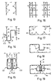
- die Fig. 1 bis 4 die Lösung der der Erfindung zugrundeliegenden Aufgabe nach dem bekannten Stand der . Technik, und zwar in
- Fig. 1 eine Stirnansicht einer Wandbewehrung im Dehnfugenbereich, wo der Einbau eines Fugenbandes unbedingt notwendig ist,
- Fig. 2 den Horizontalschnitt nach der Linie II-II der Fig. 1 mit dem im Bereich dieser Bewehrung einzubauenden vertikalen Fugenband, die
- Fig. 3 und 4 zu den Fig. 1 und 2 ähnliche Darstellungen, jedoch Fig. 3 eine Draufsicht auf eine solche Bewehrung für eine Fundamentplatte mit aufgehender Wand und Fig. 4 einen Schnitt nach der Linie IV-IV der Fig. 3 mit dem hier am Wandfuß horizontal einzubauenden Fugenband; die
- Fig. 5 und 6 je das Bewehrungselement E1, E2 in erfindungsgemäßer Z-Form, und zwar in Stirnansichten und zueinander spiegelbildlicher Anordnung vor dem Einbau, die
- Fig. 7 und 8 diese beiden Elemente E1, E2 je in zwei verschiedenen Einbaustellungen entsprechend einer Anwendung nach Fig. 2,
- Fig. 9 eine Seitenansicht eines aus mehreren Z-Bügeln bestehenden Bewehrungselementes E1,
- Fig. 10 ein gegen Fig. 5 abgeändertes Element E3 in Stirnansicht,
- Fig. 11 die zugehörige Seitenansicht,
- Fig. 12 die Stirnansichten zweier solcher Bewehrungselemente E3 in Einbaustellung entsprechend einer Anwendung nach Fig. 4,
- Fig. 13 die Endteile der Tragbewehrung einer Wand im Dehnfugenbereich in Draufsicht,
- Fig. 14 darin die Montage eines gegen Fig. 5 abgeänderten Elementes E1,
- Fig. 15 die fertiggestellte Fugenbandumwehrung mit einem weiteren Element E2, die
- Fig. 16 bis 19 zu den Fig. 13 bis 15 ähnliche Darstellungen, jedoch für eine Fundamentplatte mit aufgehender Wand, im einzelnen Fig. 16 die Draufsicht auf die obere Tragbewehrung, Fig. 17 die zugehörige Seitenansicht, Fig. 18 darin die Montage mit einem gegen Fig. 10 abgeänderten Element E4 und Fig. 19 die fertige Fugenbandumwehrung mit zwei Elementen E4 in erfindungsgemäßer Anordnung.
- 1 to 4 the solution of the problem underlying the invention according to the known prior art . Technology, namely in
- 1 is a front view of a wall reinforcement in the expansion joint area, where the installation of a joint tape is absolutely necessary,
- Fig. 2 shows the horizontal section along the line II-II of Fig. 1 with the vertical joint tape to be installed in the area of this reinforcement, the
- 3 and 4 representations similar to FIGS. 1 and 2, but FIG. 3 is a plan view of such a reinforcement for a foundation plate with a rising wall and FIG. 4 is a section along the line IV-IV of FIG. 3 with the here joint tape to be installed horizontally at the base of the wall; the
- 5 and 6 each the reinforcement element E1, E2 in the Z-shape according to the invention, namely in end views and mutually mirror-image arrangement before installation, the
- 7 and 8 these two elements E1, E2 each in two different installation positions corresponding to an application according to FIG. 2,
- 9 is a side view of a reinforcement element E1 consisting of several Z-brackets,
- 10 an element E3 modified from FIG. 5 in end view,
- 11 is the associated side view,
- 12 shows the end views of two such reinforcement elements E3 in the installed position corresponding to an application according to FIG. 4,
- 13 shows the end parts of the supporting reinforcement of a wall in the expansion joint area in a top view,
- 14 therein the assembly of an element E1 modified from FIG. 5,
- 15 shows the completed joint tape reinforcement with a further element E2
- 16 to 19 representations similar to FIGS. 13 to 15, but for a foundation plate with a rising wall, in detail FIG. 16 the top view of the upper supporting reinforcement, FIG. 17 the associated
side 18 shows the assembly with an element E4 modified from FIG. 10 and FIG. 19 shows the finished joint tape enclosure with two elements E4 in an arrangement according to the invention.
Wie aus den Fig. 1 und 2 hervorgeht, besteht eine bisherige Fugenbandumwehrung aus zwei U-Bügeln 1, die nebeneinander unter Belassung eines Abstandes angeordnet werden, und einem weiteren Bügel 2, der sich zwischen den Außenschenkeln der Bügel 1 erstreckt. Die aus diesen drei Bügeln 1, 2 bestehende Umwehrung wird an den vertikalen Tragstäben 3 in üblicher Weise befestigt. In der so hergestellten Auswechslung der Bewehrung wird zwischen den inneren Schenkeln der Bügel 1 das vertikale Fugenband 4 normal zur Auswechslungsebene angeordnet und durch die Schellen 5, welche beide Enden des Fugenbandes 4 umfassen, mit Drähten 6 an den Stäben 3 angebunden und dadurch gespannt. In dieser Weise verhindert der Bügel 2 eine Rißbildung im Bereich der Zonen A und B nach dem Fertigbetonieren.As can be seen from FIGS. 1 and 2, a previous joint tape guard consists of two
In entsprechender Weise ist man bei der Herstellung einer Umwehrung für das horizontale Fugenband einer Fundamentplatte mit aufgehender Wand vorgegangen, wie aus den Fig. 3 und 4 erkenntlich. Dabei hat der Stab 7 die Funktion des Bügels 2 in Fig. 2 zu erfüllen; er überbrückt, gehalten an Längsstäben 8, die bezüglich ihres Abstandes genau abzubiegenden Enden der Querstäbe 10 und 11, die durch die Längsstäbe 12, 13, und 14 verbunden sind. In den von Drähten 9 gehaltenen Schellen 15 ist das am Wandfuß liegende Fugenband 16 normal zur Auswechslungsebene angeordnet, und die Rißzonen A, B sind durch diese Art der Auswechslung bewehrt.A corresponding procedure has been followed in the manufacture of a barrier for the horizontal joint tape of a foundation plate with a rising wall, as can be seen from FIGS. 3 and 4. The
Gemäß den Fig. 5 bis 9 besteht das erfindungsgemäße Bewehrungselement E1 bzw. E2 aus einer Reihe von Z-Bügeln 17 bzw. 19, jeder in gebogener Z-Form, wobei an die Bügelmittelteile 17a, 19a anschließend ein oberer Schenkel 17b, 19b mit der Länge X2 und daran am Ende eine nach unten weisende Abbiegung 17c, 19c mit der Länge Y2 und ein unterer Schenkel 17d, 19d und daran am Ende eine nach oben weisende Aufbiegung 17e, 19e mit der Länge Y1 vorgesehen sind. Diese Reihe von zueinander gleichen Abstand X8 aufweisenden Z-Bügeln 17, 19 ist durch zwei Haltestäbe 18, 20 miteinander verbunden (Fig. 9). Dabei ist der äußere Haltestab 18, 20 an der Abbiegung 17c, 19c des oberen Schenkels 17b, 19b des Bügels 17, 19 angeordnet, etwa in dessen Mitte, und der innere Haltestab 18, 20 ist am Mittelteil 17a, 19a des Bügels 17,19 etwa in dessen oberem Viertelpunkt angeordnet. Die Stäbe 18, 20 sind dabei mit den Bügeln 17, 19, z. B. durch Schweißung, verbunden.According to FIGS. 5 to 9, the reinforcement element E1 and E2 according to the invention consists of a series of Z-
Maßgebend für die Anordnung der Haltestäbe 18, 20 ist, daß sie das nachfolgend beschriebene Ineinanderschieben der Elemente E1, E2 nicht behindern. Im Beispiel nach den Fig. 5 und 6 müssen daher die Haltestäbe, 18, 20 oberhalb der Enden der Schenkel 17e, 19e liegen.What is decisive for the arrangement of the
Man kann nun die nach den Fig. 5 und 6 spiegelbildlich angeordneten, unter sich gleichen oder z. B. hinsichtlich ihres Durchmessers oder ihrer Konfiguration unterschiedlichen Elemente E1 und E2 in Pfeilrichtung Pf.1 der Fig. 6 ineinanderschieben; wenn man dabei die Stellung nach Fig. 7 erreicht hat, liegt eine erfindungsgemäß ausgebildete Umwehrung für ein Fugenband, ähnlich Fig. 2, vor.You can now the mirror images arranged according to FIGS. 5 and 6, the same or z. B. with regard to their diameter or their configuration, push different elements E1 and E2 into each other in the direction of arrow Pf.1 of FIG. 6; if one has reached the position according to FIG. 7, there is a barrier for a joint tape designed according to the invention, similar to FIG. 2.
Bei dieser Anordnung nach Fig. 7 liegen die Mittelteile 17a, 19a der Bügel 17, 19 im Abstand X1 voneinander und die oberen und unteren Abbiegungen 17c, 17e und 19c, 19e genau übereinander. Die Länge X2 des oberen Schenkels 17b, 19b entspricht dem Abstand zwischen dem Mittelteil 17a des einen Bügels 17 und der Aufbiegungen 19e des anderen Bügels 19, und umgekehrt. Damit ist diese Umwehrung nach Fig. 7 für eine Minimalwandstärke von X1 + 2 . X2 = X3 geeignet.In this arrangement according to FIG. 7, the
Durch nicht so weites Ineinanderschieben der Elemente E1, E2 im Pfeilsinne Pf. 1 der Fig. 6 kann man aber auch die Stellung nach Fig. 8 vorsehen und damit, wenn die Mittelteile 17a, 19a der Bügel 17, 19 den Abstand X4 aufweisen, eine Maximalwandstärke von X4 + 2 . X2 = X7 ebenfalls noch abdecken. Man kann dabei so weit auseinandergehen, bis X5 + Y1 mindestens die Haftlänge aufweist. In dieser Weise kann man sich also verschiedener Wandstärken mit den Elementen E1, E2 anpassen. - By not pushing the elements E1, E2 so far together in the direction of arrow Pf. 1 in FIG. 6, one can also provide the position according to FIG. if the
Das Element E3 nach den Fig. 10 bis 12 unterscheidet sich von jenen nach Fig. 5 dadurch, daß der obere Schenkel 21b des Z-Bügels 21 mit der Länge X9 nicht umgebogen ist, sondern gerade vom Bügelmittelteil 21a absteht. Der untere Schenkel 21c mit der Aufbiegung 21d weist die Länge X10 auf (Fig. 10). Die Bügel 21 sind durch Haltestäbe 22 im Abstand X11 miteinander verbunden (Fig. 11). Damit ergibt sich z. B. eine Umwehrung nach Fig. 12, bei der die Mittelteile 21a der Bügel 21 im Abstand X12 liegen und die Rißzonen 24, 25 wieder abgedeckt sind. Durch Auseinanderschieben in Pfeilssinne Pf. 2 kann man sich auch hier verschiedenen Breiten einer Aussparung anpassen.The element E3 according to FIGS. 10 to 12 differs from those according to FIG. 5 in that the upper leg 21b of the Z-
Die Fig. 13 bis 15 veranschaulichen die Montage der erfindungsgemäßen Bewehrungselemente E1, E2 bei einer Anwendung nach Fig. 2. In die aus Querstäben 25 und Längsstäben 26 bestehende Tragbewehrung einer Wand (Fig. 13) wird zunächst das eine Element E1, das ähnlich zu Fig. 6 ausgebildet ist, jedoch eine Umbiegung 19e mit der Länge Y3 am unteren Schenkel 19d des Bügels 19 aufweist (Fig. 14), und anschließend das andere Element E2 eingesetzt (Fig. 15) und mit den Stäben 25, 26 verbunden, z. B. durch Binden mit Draht. Vorweg sind die Tragstäbe 28 eingefügt worden, um sie nach der Montage der Elemente E1, E2 an den Ecken anbinden zu können (Fig. 15). Dann sind die Stäbe 27 in Pfeilrichtung Pf.4 einzuschieben und festzulegen. Hierauf wird in die verbleibende Aussparung das Fugenband 29, über die an Drähten 30 gehaltenen Schellen 31, eingesetzt und gespannt. Die Rißzonen 32 sind so gut durch diese Korbbewehrung gesichert.Figs. 13 to 15 illustrate the assembly of the reinforcement elements E1 according to the invention, E2 in an application according to Fig. 2. (13 F ig.) In consisting of
Die Fig. 16 bis 19 veranschaulichen entsprechend die Montage einer Umwehrung aus Elementen E4 bei einer Fundamentplatte in Anwendung nach Fig. 4. In die aus den Querstäben 33, 35 und den Längsstäben 34 gebildete Fundamentplattenbewehrung (Fig. 16, 17) wird zunächst ein Element E4, ähnlich Fig. 10, mit Bügeln 21 und Haltestäben 22 eingesetzt und mit der Fundamentbewehrung verbunden (Fig. 18), und anschließend wird das zweite Element E4 eingeführt (Fig. 19). Im voraus sind die oberen Stäbe 36 einzulegen, und schließlich wird mit den Drähten 37, welche Bestandteile der Schellen 38 sind, das Fugenband 39 gespannt. Auch hier ergibt sich eine sichere Korbbewehrung für die Rißzonen 40.16 to 19 accordingly illustrate the installation of a reinforcement made of elements E4 in a foundation plate in the application according to FIG. 4. In the foundation plate reinforcement (FIG. 16, 17) formed from the
Im Rahmen der Erfindung sind weitere Abänderungen an den beschriebenen Ausführungsformen möglich. So können z. B. auch beide, an den Mittelteil anschließende Schenkel des Z-Bügels gerade ausgebildet sein.Within the scope of the invention, further modifications to the described embodiments are possible. So z. B. both legs of the Z-bracket adjoining the central part can also be straight.
Auch kann die Anordnung der Haltestäbe 18, 20 an anderem als dem dargestellten Ort erfolgen, wenn dabei sie nur das Ineinanderfügen des Paares von Elementen zulassen.The arrangement of the holding
Claims (4)
Applications Claiming Priority (2)
| Application Number | Priority Date | Filing Date | Title |
|---|---|---|---|
| AT2893/83 | 1983-08-10 | ||
| AT0289383A AT378981B (en) | 1983-08-10 | 1983-08-10 | REINFORCEMENT FOR STEEL CONCRETE CONSTRUCTION |
Publications (3)
| Publication Number | Publication Date |
|---|---|
| EP0133617A2 true EP0133617A2 (en) | 1985-02-27 |
| EP0133617A3 EP0133617A3 (en) | 1987-01-07 |
| EP0133617B1 EP0133617B1 (en) | 1990-05-02 |
Family
ID=3541970
Family Applications (1)
| Application Number | Title | Priority Date | Filing Date |
|---|---|---|---|
| EP84890147A Expired - Lifetime EP0133617B1 (en) | 1983-08-10 | 1984-08-01 | Reinforcement for armoured concrete constructions |
Country Status (3)
| Country | Link |
|---|---|
| EP (1) | EP0133617B1 (en) |
| AT (2) | AT378981B (en) |
| DE (1) | DE3482127D1 (en) |
Cited By (1)
| Publication number | Priority date | Publication date | Assignee | Title |
|---|---|---|---|---|
| GB2205596A (en) * | 1987-06-03 | 1988-12-14 | George Cyril Brown | A method of jointing concrete floor slabs |
Citations (4)
| Publication number | Priority date | Publication date | Assignee | Title |
|---|---|---|---|---|
| DE636104C (en) * | 1934-01-30 | 1936-10-05 | Paul Kroker | Reinforced concrete beam reinforcement insert with support members holding them at a distance from the formwork |
| DE2122851A1 (en) * | 1970-05-12 | 1971-12-02 | Oroschakoff, Georgi, Dipl.-Ing., Wien | Reinforcement for reinforced concrete structures |
| US4132045A (en) * | 1977-10-27 | 1979-01-02 | The Dayton Sure-Grip & Shore Company | Reinforcing bar support |
| DE8208261U1 (en) * | 1982-03-23 | 1982-12-30 | Drahtwerke Fischer AG, 5734 Reinach | CONNECTING BASKET FOR ARMING IRON CONCRETE CONSTRUCTIONS AND THEIR USE |
-
1983
- 1983-08-10 AT AT0289383A patent/AT378981B/en not_active IP Right Cessation
-
1984
- 1984-08-01 AT AT84890147T patent/ATE53886T1/en active
- 1984-08-01 DE DE8484890147T patent/DE3482127D1/en not_active Expired - Fee Related
- 1984-08-01 EP EP84890147A patent/EP0133617B1/en not_active Expired - Lifetime
Patent Citations (4)
| Publication number | Priority date | Publication date | Assignee | Title |
|---|---|---|---|---|
| DE636104C (en) * | 1934-01-30 | 1936-10-05 | Paul Kroker | Reinforced concrete beam reinforcement insert with support members holding them at a distance from the formwork |
| DE2122851A1 (en) * | 1970-05-12 | 1971-12-02 | Oroschakoff, Georgi, Dipl.-Ing., Wien | Reinforcement for reinforced concrete structures |
| US4132045A (en) * | 1977-10-27 | 1979-01-02 | The Dayton Sure-Grip & Shore Company | Reinforcing bar support |
| DE8208261U1 (en) * | 1982-03-23 | 1982-12-30 | Drahtwerke Fischer AG, 5734 Reinach | CONNECTING BASKET FOR ARMING IRON CONCRETE CONSTRUCTIONS AND THEIR USE |
Cited By (2)
| Publication number | Priority date | Publication date | Assignee | Title |
|---|---|---|---|---|
| GB2205596A (en) * | 1987-06-03 | 1988-12-14 | George Cyril Brown | A method of jointing concrete floor slabs |
| GB2205596B (en) * | 1987-06-03 | 1991-04-17 | George Cyril Brown | A method of jointing concrete floor slabs |
Also Published As
| Publication number | Publication date |
|---|---|
| EP0133617B1 (en) | 1990-05-02 |
| ATE53886T1 (en) | 1990-06-15 |
| ATA289383A (en) | 1985-03-15 |
| DE3482127D1 (en) | 1990-06-07 |
| AT378981B (en) | 1985-10-25 |
| EP0133617A3 (en) | 1987-01-07 |
Similar Documents
| Publication | Publication Date | Title |
|---|---|---|
| DE2058638A1 (en) | Reinforcement for reinforced concrete structures | |
| EP0299226B1 (en) | Shuttering for making concrete building-elements | |
| DE2412381B2 (en) | Fastening arrangement for boundary panels in the form of a grid | |
| DE2931563A1 (en) | Concrete wall lost formwork panel wire spacer - has asymmetrical outer H-shaped cross wire piece with longer downward section (OE 15.6.79) | |
| EP0133617B1 (en) | Reinforcement for armoured concrete constructions | |
| EP0143101B1 (en) | Reinforcement for reinforced concrete constructions | |
| WO2008128683A1 (en) | Formwork element | |
| EP0542116B1 (en) | Permanent forming element | |
| CH698206B1 (en) | Access basket for prefabricated double wall elements. | |
| DE60007824T2 (en) | girder | |
| EP0465777A1 (en) | Lattice girder | |
| AT390103B (en) | Connection reinforcement for reinforced-concrete structures | |
| DE19722028A1 (en) | Building component for heat insulation | |
| AT406281B (en) | REINFORCED CONCRETE | |
| EP2175079B1 (en) | Method for forming a rigid corner reinforcement for reinforced concrete construction, reinforcement element and rigid corner reinforcement | |
| WO1997018374A1 (en) | Prefabricated window unit | |
| AT378216B (en) | REINFORCEMENT MAT FOR STEEL CONCRETE | |
| AT378978B (en) | REINFORCEMENT FOR STEEL CONCRETE CONSTRUCTION | |
| DE1931210C (en) | Hanging ceiling | |
| CH643910A5 (en) | FENCE AREA MADE OF LATERAL AND VERTICAL RODS. | |
| DE8002299U1 (en) | PRE-CONSTRUCTION WALL ELEMENT | |
| DE3210664A1 (en) | Spacer and extension element for use in prefabricated building elements | |
| DE1658884C (en) | Buildings made of columns and prefabricated ceiling panels | |
| AT360214B (en) | REINFORCEMENT MAT | |
| DE2156140C2 (en) | Supported reinforced concrete ceiling |
Legal Events
| Date | Code | Title | Description |
|---|---|---|---|
| PUAI | Public reference made under article 153(3) epc to a published international application that has entered the european phase |
Free format text: ORIGINAL CODE: 0009012 |
|
| AK | Designated contracting states |
Designated state(s): AT CH DE FR GB IT LI NL |
|
| PUAL | Search report despatched |
Free format text: ORIGINAL CODE: 0009013 |
|
| AK | Designated contracting states |
Kind code of ref document: A3 Designated state(s): AT CH DE FR GB IT LI NL |
|
| 17P | Request for examination filed |
Effective date: 19870629 |
|
| 17Q | First examination report despatched |
Effective date: 19881212 |
|
| GRAA | (expected) grant |
Free format text: ORIGINAL CODE: 0009210 |
|
| AK | Designated contracting states |
Kind code of ref document: B1 Designated state(s): AT CH DE FR GB IT LI NL |
|
| PG25 | Lapsed in a contracting state [announced via postgrant information from national office to epo] |
Ref country code: NL Effective date: 19900502 Ref country code: IT Free format text: LAPSE BECAUSE OF FAILURE TO SUBMIT A TRANSLATION OF THE DESCRIPTION OR TO PAY THE FEE WITHIN THE PRESCRIBED TIME-LIMIT;WARNING: LAPSES OF ITALIAN PATENTS WITH EFFECTIVE DATE BEFORE 2007 MAY HAVE OCCURRED AT ANY TIME BEFORE 2007. THE CORRECT EFFECTIVE DATE MAY BE DIFFERENT FROM THE ONE RECORDED. Effective date: 19900502 Ref country code: GB Effective date: 19900502 Ref country code: FR Effective date: 19900502 |
|
| REF | Corresponds to: |
Ref document number: 53886 Country of ref document: AT Date of ref document: 19900615 Kind code of ref document: T |
|
| REF | Corresponds to: |
Ref document number: 3482127 Country of ref document: DE Date of ref document: 19900607 |
|
| PG25 | Lapsed in a contracting state [announced via postgrant information from national office to epo] |
Ref country code: AT Effective date: 19900801 |
|
| PG25 | Lapsed in a contracting state [announced via postgrant information from national office to epo] |
Ref country code: LI Effective date: 19900831 Ref country code: CH Effective date: 19900831 |
|
| EN | Fr: translation not filed | ||
| NLV1 | Nl: lapsed or annulled due to failure to fulfill the requirements of art. 29p and 29m of the patents act | ||
| GBV | Gb: ep patent (uk) treated as always having been void in accordance with gb section 77(7)/1977 [no translation filed] | ||
| PLBE | No opposition filed within time limit |
Free format text: ORIGINAL CODE: 0009261 |
|
| STAA | Information on the status of an ep patent application or granted ep patent |
Free format text: STATUS: NO OPPOSITION FILED WITHIN TIME LIMIT |
|
| 26N | No opposition filed | ||
| REG | Reference to a national code |
Ref country code: CH Ref legal event code: PL |
|
| PGFP | Annual fee paid to national office [announced via postgrant information from national office to epo] |
Ref country code: DE Payment date: 19981020 Year of fee payment: 15 |
|
| PG25 | Lapsed in a contracting state [announced via postgrant information from national office to epo] |
Ref country code: DE Free format text: LAPSE BECAUSE OF NON-PAYMENT OF DUE FEES Effective date: 20000601 |