EP0129744A2 - Tarnmaterial für die Tarnung militärischer Ziele - Google Patents
Tarnmaterial für die Tarnung militärischer Ziele Download PDFInfo
- Publication number
- EP0129744A2 EP0129744A2 EP84106347A EP84106347A EP0129744A2 EP 0129744 A2 EP0129744 A2 EP 0129744A2 EP 84106347 A EP84106347 A EP 84106347A EP 84106347 A EP84106347 A EP 84106347A EP 0129744 A2 EP0129744 A2 EP 0129744A2
- Authority
- EP
- European Patent Office
- Prior art keywords
- camouflage material
- material according
- camouflage
- threads
- electrically conductive
- Prior art date
- Legal status (The legal status is an assumption and is not a legal conclusion. Google has not performed a legal analysis and makes no representation as to the accuracy of the status listed.)
- Granted
Links
Images
Classifications
-
- F—MECHANICAL ENGINEERING; LIGHTING; HEATING; WEAPONS; BLASTING
- F41—WEAPONS
- F41H—ARMOUR; ARMOURED TURRETS; ARMOURED OR ARMED VEHICLES; MEANS OF ATTACK OR DEFENCE, e.g. CAMOUFLAGE, IN GENERAL
- F41H3/00—Camouflage, i.e. means or methods for concealment or disguise
- F41H3/02—Flexible, e.g. fabric covers, e.g. screens, nets characterised by their material or structure
-
- Y—GENERAL TAGGING OF NEW TECHNOLOGICAL DEVELOPMENTS; GENERAL TAGGING OF CROSS-SECTIONAL TECHNOLOGIES SPANNING OVER SEVERAL SECTIONS OF THE IPC; TECHNICAL SUBJECTS COVERED BY FORMER USPC CROSS-REFERENCE ART COLLECTIONS [XRACs] AND DIGESTS
- Y10—TECHNICAL SUBJECTS COVERED BY FORMER USPC
- Y10S—TECHNICAL SUBJECTS COVERED BY FORMER USPC CROSS-REFERENCE ART COLLECTIONS [XRACs] AND DIGESTS
- Y10S428/00—Stock material or miscellaneous articles
- Y10S428/919—Camouflaged article
-
- Y—GENERAL TAGGING OF NEW TECHNOLOGICAL DEVELOPMENTS; GENERAL TAGGING OF CROSS-SECTIONAL TECHNOLOGIES SPANNING OVER SEVERAL SECTIONS OF THE IPC; TECHNICAL SUBJECTS COVERED BY FORMER USPC CROSS-REFERENCE ART COLLECTIONS [XRACs] AND DIGESTS
- Y10—TECHNICAL SUBJECTS COVERED BY FORMER USPC
- Y10T—TECHNICAL SUBJECTS COVERED BY FORMER US CLASSIFICATION
- Y10T428/00—Stock material or miscellaneous articles
- Y10T428/24—Structurally defined web or sheet [e.g., overall dimension, etc.]
- Y10T428/24628—Nonplanar uniform thickness material
Definitions
- the invention relates to a camouflage material for camouflaging military targets against reconnaissance in the near and far infrared wave range as well as in the millimeter and centimeter wave radar range, with a base material constructed from threads in a net-like manner, which is formed on at least one side with electrical conductivity and has a low specific surface resistance and which is applied to it Has outer layer, which has an emission factor changing over the area in the far infrared wave range.
- camouflage nets which consist of a carrier net and camouflage material made of textile-like material applied to it.
- the camouflage material is colored in such a way that the best possible adaptation to the background in the visible WAVE range and in the near infrared range is given.
- these camouflage nets had no protection, so that they could be located for thermal imaging and radar devices.
- camouflage materials In order to obtain a broadband camouflage also in the areas of modern locating devices, i.e. in particular in the wavelength ranges in which thermal imaging and radar devices work, camouflage materials have been developed which consist of a base material, a metallic reflective layer on the base material and a camouflage paint on the reflective Layer exist (see. DE-A-27 59 651, DE-A-21 51 349).
- the camouflage paint should be formed by camouflage colors, the binding agent of which has good transparency in the spectra areas of the atmospheric windows II and III and the pigments in the visible and near IR area have a reflection similar to chlorophyll.
- the camouflage colors are thereby in this area have an over its area changing emission factor, which is preferably microns in the wavelength range of 3 to 5 is between 5o and 90% and in the wavelength range 8 to 14 microns between 6 0 and 95% vary intended.
- This variation in the emission factor gives the camouflage in the spectral range of the thermal imaging devices a structure which is matched to that of the natural background in this spectra range.
- the camouflage in the radar spectral range is achieved in that the metallic layer has a specific surface resistance of at most a few ohms / square and in that the camouflage material is in the form of a garnish with, for example, a sickle cut.
- camouflage material has been its sensitivity.
- the electrically conductive layer changes its resistance and thus its effectiveness due to the stress on the camouflage material in use so significantly that the camouflage properties suffer.
- the previously known camouflage material has a tendency to heat up more than the natural environment, in particular natural foliage, as a result of solar radiation.
- the foliage partially uses the sun's rays for photosynthesis.
- part of the absorbed energy is released into the environment through water evaporation.
- many plants change the angle of incidence of the solar radiation by changing the leaf position in order to avoid excessive heating by solar radiation.
- the warming of foliage does not depend solely on its emission coefficients, which means that a camouflaged target no longer fits into the image of the natural grasses and leaves in the background after prolonged exposure to the sun.
- the invention is therefore based on the object of improving the known camouflage material described at the outset in such a way that the camouflage effect is retained as far as possible even in the case of prolonged exposure to the sun and that the camouflage properties remain constant for a long time even under high usage stress.
- This design of the camouflage material is based on the idea already belonging to the invention of using the convection flow which forms on the camouflage material due to its heating for better heat dissipation to the air by considerably increasing the heat transfer area. Due to the free spacing of the threads, an exchange of the air flows is also possible. In this way, the warming of the camouflage material due to solar radiation is kept within the limits within which the surrounding foliage material also heats up.
- camouflage material is not affected as quickly by its use because there is no closed electrically conductive layer that could tear.
- the covering of the camouflage material is not complete due to the free spaces between the threads.
- a compromise must be made on the one hand with regard to the size of the free spaces between the threads and on the other hand with the need to cover the military target.
- Such a compromise can consist in that the free distances are at least one third of the thread thickness, better still about half the thread thickness. In this way enough space is created for the convective air flow, but on the other hand the coverage of the military target is still sufficient.
- camouflage material for example in the form of a fabric
- an electrically conductive layer is provided with an electrically conductive layer.
- This expediently consists of a binder, for example a phenolic resin binder, with electrically conductive pigments, for example graphite or soot particles.
- the binder should contain about 10 to 50% of the pigments.
- Such an electrically conductive layer can be applied in a simple manner by spraying or brushing onto the threads of the base material. The layer causes camouflage in the radar area because the radar beams are scattered in a wide variety of directions and thus a picture is created similar to that in the leaves of trees.
- the threads consist of metal. This can be done, for example, by the threads being formed from plastic-laminated aluminum strips with a width of 0.2 to 0.5 mm. The thickness of the aluminum strips can vary from 6 to 20 mm, whereby they are laminated on both sides with the same thickness.
- the surface resistance should be in a range between 2 to 50 ohms / square, since the reflection of the radar waves is particularly pronounced in this area.
- the outer layer according to the invention consists of a synthetic, open-cell foam covering.
- the foam coating should contain about 5 to 25% flaky metal pigments, for example made of copper, zinc, steel or aluminum particles. In this way, an emission factor of 70 to 95% can be achieved, which is recommended for camouflage in summer. An emission factor of 40 to 60% is sufficient for camouflage in winter.
- the emissivity or the emission factor is synonymous with the absorbency.
- the outer layer can also be a color layer which consists of a binder which is largely transparent in the infrared spectrum, such as, for example, CycLo rubber, polyethylene or polypropylene, and platelet-shaped metal pigments, such as, for example, chromium oxides, iron oxides or titanium oxides, or mineral pigments, such as, for example, Sienna, KaLk or cobalt blue.
- a binder which is largely transparent in the infrared spectrum
- platelet-shaped metal pigments such as, for example, chromium oxides, iron oxides or titanium oxides, or mineral pigments, such as, for example, Sienna, KaLk or cobalt blue.
- the basic idea of the present invention can alternatively or in combination with the first proposal according to the invention also be realized in that the camouflage material of the type mentioned above is provided over the surface with depressions and / or projections, which are preferably embossed.
- This measure also considerably increases the heat transfer area for the convective air flow, as a result of which better heat transfer to the ambient air is achieved.
- the consequence of this is that the camouflage material heats up less when exposed to sunlight, even if the camouflage material is formed without free spaces between the threads. In the latter case, then but the electrically conductive formation and the outer layer can be formed in the same way as in the camouflage material with the free spaces between the threads.
- the depressions or projections can be hemispherical and / or conical, for example. In both cases, an increase in the heat transfer area and a scattering of the reflected radar beams is achieved.
- the depressions and / or the projections can have a depth or height of approximately 5 to 25 mm and a diameter of the same order of magnitude.
- the dimensions of the depressions or projections should expediently change distributed over the surface.
- the projections can also be designed in the form of ribs by appropriate folding of the camouflage material.
- the invention provides that spots of the camouflage material are applied irregularly distributed on a support net, the support net should consist of the open-mesh camouflage material.
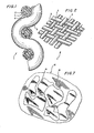
- the camouflage material 1 shown in Figures 1 and 2 is designed as a carrier fabric, which consists of crossing threads 2, 3. Plastic monofilaments are particularly suitable as the material for the threads 2, 3.
- the threads 2, 3 are surrounded by an electrically conductive layer 4, which has been applied by means of an impregnation technique.
- Their conductivity is brought about by electrically conductive pigments, such as graphite or carbon black.
- the graphite or carbon black particles are contained in an amount of 10 to 50% in a phenolic resin binder.
- the electrically conductive layer 4 appears black.
- this layer 4 is a synthetic, open cell Foam covering 5 applied, namely by immersing in an appropriate bath and then foaming and drying.
- the open cell structure of this foam covering increases the heat transfer area effective for air convection.
- the foam covering 5 can consist, for example, of polyurethane, polyLefin, polyvinyl chloride, polyester, polyether, polystyrene or polyacrylate. About 5 to 25% of metal pigments, for example copper, zinc, steel or preferably aluminum flakes, are embedded in the foam covering 5 in order to achieve a desired emission factor.
- the emission factor or emissivity should lie between 70 and 95% of the black body, while for winter camouflage an emissivity of 40 to 60X is sufficient.
- the emissivity should change continuously over the area within the aforementioned ranges in order to tear apart the representation in the thermal imaging device and to adapt it to the representation of the natural environment.
- the crossing threads 2, 3 run at a distance from each other, so that gaps 6 arise. This also contributes to the improvement of the heat transfer, since the heat transfer area for the convective air flow is thereby increased. This has the consequence that the camouflage material 1 is no longer heated as much by the sun's radiation as was the case with the known material.
- the distance a between two adjacent threads 2 it has been found to make the distance a between two adjacent threads 2 approximately half to one third as large as the thickness b of the Fadens 2 to design yourself.
- a corresponding treatment as is customary in the textile industry, can follow to fix the threads 2, 3.
- camouflage material 7 is shown in FIG. This camouflage material 7 is also woven from threads 8.
- the camouflage material 7 shown here is not air-permeable.
- the threads 8 and the gaps existing between them are surrounded or filled with an electrically conductive layer 9, which can consist of the same material as the electrically conductive layer 4 in the embodiment according to FIGS. 1 and 2.
- an electrically conductive layer 9 On both sides of the electrically conductive layer 9 are color layers 1 0, 11 applied with a color binder is transparent in the thermal infrared range, that is, for example, cyclo rubber, polyethylene or polypropylene. In this color binder, just like in the foam coating 5 in the embodiment according to FIGS.
- metal pigments are incorporated, with which the emissivity can be set in the desired range, with the target, the best possible adaptation to the emissivity of the surrounding nature to reach.
- color layers 1 0, 11 and foam coverings of the type can be applied as they are provided for the camouflage material 1 according to Figures 1 and 2, of course.
- the threads 8 of the camouflage material 7 can also be made of plastic, such as polyester, nylon, polyethylene, polypropylene or other filaments stand.
- the threads 8 of the camouflage material 7 - like the threads 2, 3 of the camouflage material 1 according to FIGS. 1 and 2 - can also be electrically conductive.
- the threads 2, 3, 8 are then produced in such a way that a thin aluminum foil with a thickness of 6 to 20 ⁇ m is laminated on both sides with a thin polyester film which can have a thickness of 6 to 20 ⁇ m in each case. This material is then cut into endless threads with a width of 0.2 to 0.5 mm.
- the threads can then partially or completely replace the plastic threads 2, 3, 8 in the camouflage materials 1, 7.
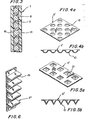
- the camouflage material 7 according to FIG. 3 has an increased heat transfer surface for the convection air flow passing by, its surface is additionally structured, as can be seen from FIGS. 4, 5 and 6.
- the camouflage material 7 ' is provided with cup-shaped recesses 12.
- pyramid-shaped depressions 13 are provided. Both types of depressions 12, 13 have been impressed by appropriately engraved calenders or rollers. The depressions 12, 13 not only have the task of increasing the heat transfer area, but are also intended to scatter the radar beams reflected by the respective electrically conductive layer 9 in a wide variety of directions.
- the camouflage material 7 ''' is folded in such a way that rib-shaped projections 14 are formed.
- These projections 14 have the same effect as the depressions 12, 13 in the camouflage materials 7 'and 7''in Figures 4 and 5.
- FIG. 7 shows a camouflage net 15 which consists of a support net 16 and colored patches 17 applied thereon in an irregular shape and at intervals.
- the spots 17 are cut out of the camouflage material 7 according to FIGS. 3 to 6.
- the support net 16 consists of the camouflage material 1 according to FIGS. 1 and 2.
- the support net 16 and / or the stains 17 - in the latter case before being applied to the support net 16 - can be provided with incisions.
- the electrically conductive paint can be applied by spraying, rolling or soaking. After drying the fabric to remove the solvent, it is immersed in a solution of 55% PVC and 45% PhthaLate plasticizer, which contains color and metallic pigments. After drying to form a foam covering, spots are clipped onto the fabric. These patches consist of a woven textile material of approximately 12 threads per cm, which is covered on both sides with an electrically conductive layer.
- Color layers are applied to this layer on both sides, which has a binder that is essentially transparent in the thermal infrared range and contains pigments reflecting heat radiation. whose colors also have a camouflaging effect in the visible area.
- the textile material is provided with embossed recesses, which have been embossed using an appropriate embossing calender.
- polyester fibers are used instead of polypropylene monofilaments.
- the electrically conductive layer contains aluminum particles and the foam covering consists of a pre-expanded acrylic dispersion.
- individual threads are woven into the textile material that are themselves electrically conductive, since they consist of plastic-laminated aluminum strips.
Abstract
Description
- Die Erfindung betri ft ein Tarnmaterial für die Tarnung militärischer Ziele gegen Aufklärung im nahen und fernen Infrarotwellenbereich sowie im Millimeter- und Zentimeterwellen-Radarbereich, mit einem aus Fäden netzartig aufgebauten Grundmaterial, das zumindest einseitig elektrisch Leitend mit geringem spezifischen Flächenwiderstand ausgebildet ist und eine darauf aufgebrachte Außenschicht aufweist, die im fernen Infrarotwellenbereich einen sich über die Fläche ändernden Emissionsfaktor hat.
- MiLitärische ZieLe werden übticherweise mit Tarnnetzen abgedeckt, die aus einem Tragnetz und darauf aufgebrachtem Tarnmaterial aus textilähnlichem Material bestehen. Das Tarnmaterial ist dabei derart eingefärbt, daß eine möglichst gute Anpassung an den Hintergrund im sichtbaren WeLLenbereich und im nahen Infrarotbereich gegeben ist. Im fernen Infrarotwellenbereich, also in den SpektraLbereichen 3 bis 5 µm und 8 bis 14 µm (atmosphärische Fenster II und III) sowie im Radarbereich wiesen diese Tarnnetze keinen Schutz auf, so daß sie für Wärmebild-und Radargeräte ortbar waren.
- Um eine breitbandigere Tarnung auch in den Bereichen moderner Ortungsgeräte zu erhalten, also insbesondere in den Wellenlängenbereichen, in denen Wärmebild-und Radargeräte arbeiten, sind Tarnmaterialien entwickelt worden, die aus einem GrundmateriaL, einer metallisch reflektierenden Schicht auf dem Grundmaterial sowie einem Tarnanstrich auf der reflektierenden Schicht bestehen (vgl. DE-A-27 59 651, DE-A-21 51 349). Nach der Lehre der erstgenannten Druckschrift soll der Tarnanstrich durch Tarnfarben gebildet sein, dessen Bindemittel in den SpektraLbereichen der atmosphärischen Fenster II und III eine gute Transparenz aufweist und dessen Pigmente im sichtbaren und nahen IR-Bereich eine dem Chlorophyll ähnLiche Reflektion haben. Die Tarnfarben sollen dabei in diesem Bereich einen über ihre Fläche sich ändernden Emissionsfaktor haben, der vorzugsweise im WellenLängenbereich von 3 bis 5 µm zwischen 5o und 90 % und im WeLLenLängenbereich von 8 bis 14 µm zwischen 60 und 95 % variieren soll. Durch diese Variation des Emissionsfaktors erhält die Tarnung im Spektralbereich der Wärmebildgeräte eine Struktur, die der des natürlichen Hintergrundes in diesem SpektraLbereich angepaßt ist.
- Die Tarnung im Radarspektralbereich wird dadurch erzielt, daß die metallische Schicht einen spezifischen FLächenwiderstand von maximal einigen Ohm/Quadrat besitzt und daß das Tarnmaterial in Form einer Garnierung mit beispielsweise Sichetschnitt vorliegt. Durch die Kombination von Garnierung und geringem Flächenwiderstand werden die Radarwellen wie das Laub von Bäumen zerstreut, so daß die sich dahinter befindenden Ziele für Radar unsichtbar bleiben.
- Als nachteilig bei dieser Art von Tarnmaterial hat sich zum einen deren Empfindlichkeit erwiesen. Die elektrisch leitende Schicht ändert ihren Widerstand und damit ihre Wirksamkeit auf Grund der Beanspruchung des Tarnmaterials im Gebrauch so erheblich, daß darunter die Tarneigenschaften leiden.
- Zum anderen hat das vorbekannte Tarnmaterial die Neigung, sich durch Sonneneinstrahlung stärker zu erwärmen als die natürliche Umgebung, insbesondere natürliches Laubwerk. Das Laubwerk nutzt nämlich die Sonneneinstrahlung teilweise zur Fotosynthese. Außer- dem wird ein Teil der absorbierten Energie in die Umgebung durch Wasserverdunstung wieder abgegeben. Ferner ändern viele PfLanze den Einfallswinkel der Sonneneinstrahlung durch Ändern der Blattstellung, um eine zu starke Erwärmung durch SonneneinstrahLung zu vermeiden. Die Erwärmung von Laubwerk hängt somit nicht allein von dessen Emissionskoeffizienten ab, was zur FoLge hat, daß sich ein getarntes Ziel nach Längerer Sonneneinstrahlung nicht mehr in das BiLd der natürlichen Gräser und BLätter des Hintergrundes einfügt.
- Der Erfindung liegt somit die Aufgabe zugrunde, das bekannte, eingangs beschriebene Tarnmaterial so zu verbessern, daß die Tarnwirkung auch bei längerer Sonneneinstrahlung möglichst weitgehend erhalten bleibt und daß ferner die Tarneigenschaften auch bei hoher Gebrauchsbeanspruchung Lange konstant bleiben.
- Diese Aufgabe wird erfindungsgemäß dadurch gelöst, daß die Fäden zwischen sich freie Abstände haben und demgemäß die elektrisch leitende Ausbildung des Grundmaterials und die Außenschicht auf die Fäden selbst beschränkt sind.
- Dieser Ausbildung des Tarnmaterials liegt die schon zur Erfindung gehörende Idee zugrunde, die sich am Tarnmaterial auf Grund dessen Erwärmung bildende Konvektionsströmung zur besseren Wärmeabgabe an die Luft zu nutzen, indem die Wärmeübergangsfläche erheblich vergrößert wird. Durch die freien Abstände der Fäden ist zudem ein Austausch der Luftströmungen möglich. Auf diese Weise hält sich die Erwärmung des Tarnmaterials infolge SonneneinstrahLung in den Grenzen, in denen auch eine Erwärmung des umgebenden Laubmaterials eintritt.
- Hinzu kommt, daß das Tarnmaterial hinsichtlich seiner Tarneigenschaften nicht so schnell durch den Gebrauch beeinträchtigt wird, da keine geschlossene elektrisch leitende Schicht vorhanden ist, die reißen könnte.
- Erfindungsgemäß ist die Abdeckung des Tarnmaterials auf Grund der freien Abstände zwischen den Fäden nicht vollständig. Dabei muß ein Kompromiß einerseits hinsichtlich der Größe der Freiräume zwischen den Fäden und andererseits der Notwendigkeit der Bedeckung des militärischen Ziels geschlossen werden. Ein solcher Kompromiß kann darin bestehen, daß die freien Abstände zumindest ein Drittel der Fadendicke, besser noch etwa die Hälfte der Fadendicke, betragen. Auf diese Weise ist genügend PLatz für die konvektive Luftströmung geschaffen, andererseits aber die Bedeckung des militärischen Ziels noch ausreichend.
- Die Fäden zur BiLdung der netzartigen Struktur des Tarnmaterials beispielsweise in Form eines Gewebes sind in einer Ausführungsform mit einer elektrisch leitenden Schicht versehen. Diese besteht zweckmäßigerweise aus einem Binder, beispielsweise einem Phenolharzbinder, mit elektrisch leitenden Pigmenten, beispielsweise Graphit oder RußteiLchen. Dabei sollten die Pigmente zu etwa 10 bis 50 % im Binder enthalten sein. Eine solche elektrisch Leitende Schicht läßt sich auf einfache Weise durch Aufsprühen oder Aufstreichen auf die Fäden des Grundmaterials auftragen. Die Schicht bewirkt die Tarnung im Radarbereich, weil die Radarstrahlen in die verschiedensten Richtungen zerstreut werden und somit ein ähnliches BiLd entsteht wie bei dem Laub von Bäumen.
- Alternativ oder in Kombination dazu kann vorgesehen sein, daß zumindest ein Teil der Fäden aus Metall besteht. Dies kann beispielsweise dadurch geschehen, daß die Fäden aus kunststofflaminierten Aluminiumstreifen mit einer Breite von 0,2 bis 0,5 mm gebilde: sind. Die Dicke der Aluminiumstreifen kann von 6 bis 20 mm variieren, wobei sie beidseitig in gleicher Dicke kunststofflaminiert sind.
- In beiden FäLLen sollte der FLächenwiderstand in einem Bereich zwischen 2 bis 50 Ohm/Quadrat Liegen, da in diesem Bereich die Reflektion der Radarwellen besonders ausgeprägt ist.
- In einer vorteilhaften Ausführungsform besteht die Außenschicht erfindungsgemäß aus einem synthetischen, offenzelligen SchaumbeLag. Hierdurch wird die für die Wärmeübertragung wirksame OberfLäche noch einmal erheblich vergrößert, was ebenfalls einer übermäßigen Erwärmung des Tarnmaterials infolge SonneneinstrahLung entgegenwirkt.
- Um das Emissionsvermögen an die natürliche Umgebung anzugleichen, sollte der SchaumbeLag etwa 5 bis 25 % blättchenförmige Metallpigmente, beispielsweise aus Kupfer, Zink, StahL oder Aluminiumteilchen, enthalten. Auf diese Weise läßt sich ein Emissionsfaktor von 70 bis 95 % erzielen, wie er für die Tarnung im Sommer empfehlenswert ist. Für die Tarnung im Winter reicht ein Emissionsfaktor von 40 bis 60 % aus. Das Emissionsvermögen bzw. der Emissionsfaktor ist dabei synonym mit dem Absorptionsvermögen.
- Alternativ dazu kann die Außenschicht auch eine Farbschicht sein, die aus einem im Infrarotspektrum weitgehend transparenten Binder besteht, wie beispielsweise CycLo-Kautschuk, Polyäthylen oder Polypropylen sowie blättchenförmige Metallpygmente, wie beispielsweise Chromoxiden, Eisenoxiden oder Titanoxiden, oder mineralische Pigmente, wie beispielsweise Sienna, KaLk oder Kobaltblau.
- Die Grundidee der vorliegenden Erfindung kann aber alternativ oder in Kombination zu dem ersten erfindungsgemäßen VorschLag auch dadurch verwirklicht werden, daß das Tarnmaterial der eingangs genannten Art über die FLäche verteilt mit Vertiefungen und/oder Vorsprüngen versehen wird, die vorzugsweise eingeprägt sind. Durch diese Maßnahme wird ebenfalls die Wärmeübertragungsfläche für die konvektive Luftströmung erheblich vergrößert, wodurch ein besserer Wärmeübergang an die Umgebungsluft erreicht wird. Dies hat zur Folge, daß sich das Tarnmaterial bei Sonneneinstrahlung weniger erhitzt, und zwar auch dann, wenn das Tarnmaterial ohne freie Abstände zwischen den Fäden ausgebildet wird. Im Letzteren Fall kann dann aber die elektrisch leitende Ausbildung und die Außenschicht in gleicher Weise ausgebildet sein wie bei dem Tarnmaterial mit den freien Abständen zwischen den Fäden.
- Die Vertiefungen bzw. Vorsprünge können beispielsweise halbkugel- und/oder kegelförmig ausgebildet sein. In beiden FäLLen wird eine Vergrößerung der Wärmeübertragungsfläche sowie ein Zerstreuen der reflektierten Radarstrahlen erreicht.
- Die Vertiefungen und/oder die Vorsprünge können eine Tiefe bzw. Höhe von ca. 5 bis 25 mm and einen Durchmesser in gleicher Größenordnung aufweisen. Zweckmäßigerweise sollten sich die Dimensionen der Vertiefungen bzw. Vorsprünge über die FLäche verteilt ändern.
- Alternativ dazu können die Vorsprünge auch rippenförmig durch entsprechende Faltung des Tarnmaterials ausgebildet sein.
- Die Erfindung sieht schließlich vor, daß Flecken des Tarnmaterials auf einem Tragnetz unregelmäßig verteilt aufgebracht sind, wobei das Tragnetz aus dem offenmaschigen Tarnmaterial bestehen soLLte.
- In der Zeichnung ist die Erfindung ar Hand von Ausführungsbeispielen näher veranschaulicht. Es zeigen:
- Figur 1 eine teilweise Querschnittsansicht eines Tarnmaterials;
- Figur 2 eine teilweise perspektivische Ansicht des Tarnmaterials gemäß Figur 1;
- Figur 3 eine teilweise Querschnittsansicht eines anderen TarnmateriaLs;
- Figur 4a eine perspektivische TeiLansicht eines geprägten Tarnmaterials nach Figur 3;
- Figur 4b eine Querschnittsansicht des Tarn- materials nach Figur 4a;
- Figur 5a ein anders geprägtes Tarnmaterial nach Figur 3 in perspektivischer Ansicht;
- Figur 5b eine Querschnittsansicht des Tarnmater als nach Figur 5a;
- Figur 6 eine teilweise perspektivische Ansicrt eines rippenförmigen Tarnmater-als nach Figur 3 und
- Figur 7 eine teilweise schematische Ansicht eines Tarnnetzes mit FLecken des Tarnmaterials nach Figur 3.
- Das in den Figuren 1 und 2 dargestellte Tarnmaterial 1 ist als Trägergewebe ausgebildet, das aus sich kreuzenden Fäden 2, 3 besteht. Als Material für die Fäden 2, 3 kommen insbesondere Kunststoffmonofile in Frage.
- Die Fäden 2, 3 sind, wie insbesondere aus Figur 1 zu sehen ist, von einer elektrisch Leitenden Schicht 4 umgeben, die mittels einer Imprägnierungstechnik aufgetragen worden ist. Deren Leitfähigkeit wird durch elektrisch leitende Pigmente, wie beispielsweise Graphit oder Ruß, bewirkt. Die Graphit- oder Rußteilchen sind in einer Menge von 10 bis 50% in einem Phenolharzbinder enthalten. Die elektrisch Leitende Schicht 4 erscheint dabei schwarz.
- Auf diese Schicht 4 ist ein synthetischer, offenzelliger Schaumbelag 5 aufgetragen, und zwar durch Eintauchen in ein entsprechendes Bad und anschließender Aufschäumung und Trocknung. Die offene Zellenstruktur dieses Schaumbelages vergrößert den für die Luftkonvektion wirksamen Wärmeübergangsbereich.
- Der Schaumbelag 5 kann beispielsweise aus PoLyurethan, PoLyoLefin, Polyvinylchlorid, Polyester, PoLyäther, Polystyren oder Polyacrylat bestehen. In dem Schaumbelag 5 sind ungefähr 5 bis 25% MetaLLpigmente, beispielsweise Kupfer, Zink, Stahl oder vorzugsweise Aluminiumblättchen, eingelagert, um einen gewünschten Emissionsfaktor zu erreichen. Für die Sommertarnung sollte der Emissionsfaktcr bzw. das Emissionsvermögen zwischen 70 und 95% des schwarzen Körpers Liegen, während für die Wintertarnurg ein Emissionsvermögen von 40 bis 60X ausreichend ist. Dabei sollte sich das Emissionsvermögen über die Fläche andauernd innerhalb der vorgenannten Bereiche ändern, um die DarsteLLung im Wärmebildgerät auseinanderzureißen und an die Darstellung der natürlichen Umgebung anzupassen.
- Wie sich insbesondere aus Figur 2 ersehen läßt, verlaufen die jeweils sich kreuzenden Fäden 2, 3 im Abstand zueinander, so daß Lücken 6 entstehen. Auch dies trägt zur Verbesserung des Wärmeübergangs bei, da die Wärmeübertragungsfläche für die konvektive Luftströmung hierdurch vergrößert wird. Dies hat zur FoLge, daß sich das Tarnmaterial 1 durch die SonnenstrahLung nicht mehr so stark erhitzt, wie dies bei dem bekannten Material der Fall war. Als günstigen Kompromiß zwischen mögLichst guter Abdeckung des zu tarnenden ZieLes und möglichst guter LuftdurchLässigkeit hat es sich erwiesen, den Abstand a zwischen zwei benachbarten Fäden 2 etwa halb bis ein DritteL so groß wie die Dicke b des Fadens 2 selbst zu gestalten. Zur Fixierung der Fäden 2, 3 kann sich eine entsprechende Behandlung anschließen, wie sie in der Textilindustrie üblich ist.
- In Figur 3 ist eine andere Ausführungsform eines Tarnmaterials 7 dargestellt. Auch dieses Tarnmaterial 7 ist aus Fäden 8 gewebt.
- Im Unterschied zu dem in den Figuren 1 und 2 darge- stellten Tarnmaterial 1 ist das hier dargestellte Tarnmaterial 7 jedoch nicht luftdurchlässig ausgebildet. Die Fäden 8 sowie die zwischen ihnen bestehenden Lükken sind mit einer elektrisch Leitenden Schicht 9 umgeben bzw. ausgefüllt, die aus dem gleichen Material bestehen kann wie die elektrisch Leitende Schicht 4 bei dem Ausführungsbeispiel nach den Figuren 1 und 2. Auf beide Seiten der elektrisch Leitenden Schicht 9 sind Farbschichten 10, 11 aufgetragen, deren Farbbinder im thermischen Infrarotbereich transparent ausgebildet ist, also beispielsweise aus Cyclo-Kautschuk, PoLyäthyLen oder Polypropylen bestehen. In diesem Farbbinder sind hier ebenso wie in dem SchaumbeLag 5 bei dem Ausführungsbeispiel nach den Figuren 1 und 2 MetaLLpigmente eingelagert, mit denen sich das Emissionsvermögen in dem jeweils gewünschten Bereich einstellen läßt, mit dem ZieL, eine möglichst gute Anpassung an das Emissionsvermögen der umgebenden Natur zu erreichen. ALternativ zu den Farbschichten 10, 11 können selbstverständlich auch Schaumbeläge der Art aufgetragen werden, wie sie für das Tarnmaterial 1 nach den Figuren 1 und 2 vorgesehen sind.
- Die Fäden 8 des Tarnmaterials 7 können auch hier wieder aus Kunststoff, wie beispielsweise Polyester, Nylon, Polyäthylen, PoLypropyLen oder anderen Filamenten bestehen. Die Fäden 8 des Tarnmaterials 7 können jedoch - ebenso wie die Fäden 2, 3 des Tarnmaterials 1 nach den Figuren 1 und 2 - auch selbst elektrisch Leitend ausgebildet werden. Die Herstellung der Fäden 2, 3, 8 geschieht dann so, daß eine dünne Aluminiumfolie mit einer Stärke von 6 bis 20 um beidseitig mit einem dünnen PoLyesterfiLm kaschiert wird, der eine Stärke von jeweils 6 bis 20 µm haben kann. Dieses Material wird dann zu endlosen Fäden in der Breite von 0,2 bis 0,5 mm geschnitten. Die Fäden können dann die Kunststoff-Fäden 2, 3, 8 in den Tarnmaterialien 1, 7 teilweise oder ganz ersetzen.
- Damit das Tarnmaterial 7 gemäß Figur 3 eine erhöhte Wärmeübergangsfläche für die vorbeistreifende Konvektions uftströmung hat, wird seine FLäche zusätzLich strukturiert, wie dies aus den Figuren 4, 5 und 6 zu ersehen ist. Bei dem Beispiel nach den Figuren 4a und 4t ist das Tarnmaterial 7' mit napfförmigen Vertiefurgen 12 versehen. Bei dem Beispiel nach den Figuren 5a und 5b sind pyramidenförmige Vertiefungen 13 vorgesehen. Beide Arten von Vertiefungen 12, 13 sind durch entsprechend gravierte KaLander bzw. Walzen eingeprägt worden. Dabei haben die Vertiefungen 12, 13 nicht nur die Aufgabe, die Wärmeübertragungsfläche zu vergrößern, sondern sollen auch die von der jeweils elektrisch Leitenden Schicht 9 reflektierten RadarstrahLen in die verschiedensten Richtungen streuen.
- Bei dem Beispiel nach Figur 6 ist das Tarnmaterial 7''' derart gefaltet, daß sich rippenförmige Vorsprünge 14 bilden. Diese Vorsprünge 14 haben die gleich Wirkung wie die Vertiefungen 12, 13 bei den Tarnmaterialien 7' bzw. 7'' in den Figuren 4 und 5.
- Figur 7 zeigt ein Tarnnetz 15, das aus einem Tragnetz 16 sowie darauf in unregelmäßiger Form und Abständen aufgebrachten, farbigen FLecken 17 besteht. Die Flecken 17 sind aus dem Tarnmaterial 7 gemäß den Figuren 3 bis 6 ausgeschnitten. Das Tragnetz 16 besteht aus dem Tarnmaterial 1 gemäß den Figuren 1 und 2.
- Für den koventionellen Wärmeaustausch können das Tragnetz 16 und/oder die FLecken 17 - im Letzteren FaLL vor dem Aufbringen auf das Tragnetz 16 - mit Einschnitten versehen werden.
- Ein Gewebe, hergestellt aus Polypropylen-Monofilen mit einem Durchmesser von ungefähr 0,5 mm, wird mit einem elektrisch leitenden Lack von ungefähr 50 g/m2 be- schichtet, wobei der Lack 12 bis 20% Ruß oder Graphit oder eine Mischung daraus enthält. Der elektrisch Leitende Lack kann durch Spritzen, RoLLen oder Tränken aufgetragen sein. Nach dem Trocknen des Gewebes zur Entfernung des LösungsmitteLs wird es in eine Lösung von 55% PVC und 45% PhthaLate-Weichmacher eingetaucht, das Farbe und MetaLLpigmente enthält. Nach der Trocknung zur Bildung eines Schaumbelages werden auf das Gewebe Flecken aufgeklipst. Diese FLecken bestehen aus einem gewebten TextiLmateriaL von ungefähr 12 Fäden pro cm, das auf beiden Seiten mit einer elektrisch Leitenden Schicht bedeckt ist. Auf diese Schicht werden beidseitig Farbschichten aufgetragen, die einen im thermischen Infrarotbereich im wesentlichen transparenten Binder hat und Wärmestrahlung reflektierende Pigmente enthält, deren Farben im sichtbaren Bereich ebenfalls tarnend wirken. Das textile Material ist mit eingeprägten Vertiefungen versehen, die mittels eines entsprechenden Prägekalanders eingeprägt worden sind.
- Für das im Beispiel 1 beschriebene Gewebe werden anstatt Polypropylen-Monofilen PoLyesterfasern verwendet. Die elektrisch Leitende Schicht enthält ALuminiumteilchen und der Schaumbelag besteht aus einer vorgeschäumten Acrylatdispersion. Um die Leitfähigkeit im Hochfrequenz-Radarbereich zu verbessern, werden vereinzelt Fäden in das textile Material eingewebt, die selbst elektrisch Leitend sind, da sie aus kunststofflaminierten Aluminiumstreifen bestehen.
Claims (18)
Priority Applications (1)
| Application Number | Priority Date | Filing Date | Title |
|---|---|---|---|
| AT84106347T ATE29924T1 (de) | 1983-06-27 | 1984-05-30 | Tarnmaterial fuer die tarnung militaerischer ziele. |
Applications Claiming Priority (2)
| Application Number | Priority Date | Filing Date | Title |
|---|---|---|---|
| US507969 | 1983-06-27 | ||
| US06/507,969 US4465731A (en) | 1983-06-27 | 1983-06-27 | Universal camouflage for military objects |
Publications (3)
| Publication Number | Publication Date |
|---|---|
| EP0129744A2 true EP0129744A2 (de) | 1985-01-02 |
| EP0129744A3 EP0129744A3 (en) | 1985-11-06 |
| EP0129744B1 EP0129744B1 (de) | 1987-09-23 |
Family
ID=24020840
Family Applications (1)
| Application Number | Title | Priority Date | Filing Date |
|---|---|---|---|
| EP84106347A Expired EP0129744B1 (de) | 1983-06-27 | 1984-05-30 | Tarnmaterial für die Tarnung militärischer Ziele |
Country Status (5)
| Country | Link |
|---|---|
| US (1) | US4465731A (de) |
| EP (1) | EP0129744B1 (de) |
| AT (1) | ATE29924T1 (de) |
| CA (1) | CA1230969A (de) |
| DE (1) | DE3466432D1 (de) |
Cited By (5)
| Publication number | Priority date | Publication date | Assignee | Title |
|---|---|---|---|---|
| EP0311698A2 (de) * | 1987-06-24 | 1989-04-19 | Fibrotex Ltd. | Dreidimensionales Tarn-Netz |
| DE3840664A1 (de) * | 1988-12-02 | 1990-06-07 | Messerschmitt Boelkow Blohm | Multispektrales tarnnetz (radartarnnetz) |
| WO1991019950A1 (en) * | 1990-06-14 | 1991-12-26 | Barracuda Technologies Ab | Thermal and visual camouflage |
| DE29716362U1 (de) * | 1996-09-14 | 1998-01-08 | Ploucquet C F Gmbh | Wärmetarnplane |
| RU2546470C1 (ru) * | 2014-03-03 | 2015-04-10 | Сергей Александрович Филин | Маскировочная сеть |
Families Citing this family (22)
| Publication number | Priority date | Publication date | Assignee | Title |
|---|---|---|---|---|
| US4529633A (en) * | 1983-01-14 | 1985-07-16 | Diab-Barracuda Ab | Thermal camouflage |
| SE457115B (sv) * | 1983-03-25 | 1988-11-28 | Diab Barracuda Ab | Termisk och optisk kamouflage |
| US4621012A (en) * | 1984-11-15 | 1986-11-04 | Gunter Pusch | Camouflage net having a semiconductive layer |
| US4728677A (en) * | 1986-05-30 | 1988-03-01 | The B. F. Goodrich Company | Weatherable vinyl polymer compositions |
| US4766610A (en) * | 1987-01-22 | 1988-08-30 | Varo, Inc. | Replaceable cushion liner for military headgear |
| US4741054A (en) * | 1987-01-22 | 1988-05-03 | Varo, Inc. | Chin cup for use with military headgear |
| JPS63159696U (de) * | 1987-04-08 | 1988-10-19 | ||
| JPS63159695U (de) * | 1987-04-08 | 1988-10-19 | ||
| JPS63159697U (de) * | 1987-04-08 | 1988-10-19 | ||
| DE68920756D1 (de) * | 1988-02-19 | 1995-03-09 | Wilkie J & D Ltd | Thermischer Tarnungsstoff. |
| DE3810121A1 (de) * | 1988-03-25 | 1989-10-05 | Hornschuch Ag K | Tarnnetz und verfahren zu seiner herstellung |
| JPH0689998B2 (ja) * | 1988-08-11 | 1994-11-14 | 東レ株式会社 | 遠赤外線偽装材用補助材料 |
| GB2237862B (en) * | 1989-10-30 | 1994-07-06 | Colebrand Ltd | Absorbers |
| US5955175A (en) * | 1996-09-20 | 1999-09-21 | W. L. Gore & Associates, Inc. | Infra-red reflective coverings |
| SE513643C2 (sv) | 1998-09-07 | 2000-10-16 | Barracuda Tech Ab | Maskeringsmaterial med optisk maskeringsverkan, med tredimensionell ytstruktur |
| WO2001025715A2 (en) * | 1999-10-01 | 2001-04-12 | Larue John L | Camouflaged structure and method of camouflaging a structure |
| DE10240802A1 (de) * | 2002-08-30 | 2004-04-15 | W.L. Gore & Associates Gmbh | IR reflektierendes Material |
| KR100775127B1 (ko) * | 2005-12-14 | 2007-11-08 | 삼양화학공업주식회사 | 무전해 도금 섬유를 이용한 위장직물 |
| US8075567B2 (en) * | 2007-03-22 | 2011-12-13 | Anchor Products Company | Surgical tissue retrieval instrument |
| US9668530B2 (en) * | 2013-01-30 | 2017-06-06 | Stephen D. Miller | Resilient prominence fabric and articles made therefrom |
| CN106364106B (zh) * | 2016-08-17 | 2019-05-31 | 浙江盛发纺织印染有限公司 | 一种反侦察装备专用面料 |
| USD820604S1 (en) * | 2017-10-20 | 2018-06-19 | Nike, Inc. | Garment |
Citations (10)
| Publication number | Priority date | Publication date | Assignee | Title |
|---|---|---|---|---|
| DE1056508B (de) * | 1955-05-26 | 1959-04-30 | Ekman & Brundin | Verfahren zum Herstellen von Tarnnetzen |
| FR1233225A (fr) * | 1959-07-20 | 1960-10-12 | Albert Markmann & Co | Tissu ininflammable, notamment pour décoration et camouflage |
| US3119729A (en) * | 1955-06-13 | 1964-01-28 | Ljungbo Sven Olof Birger | Camouflage net |
| FR2131929A1 (de) * | 1971-04-06 | 1972-11-17 | Barracudaverken Ab | |
| FR2308079A1 (fr) * | 1975-04-16 | 1976-11-12 | Barracudaverken Ab | Bache de camouflage |
| FR2311117A1 (fr) * | 1975-05-13 | 1976-12-10 | Barracudaverken Ab | Etoffe de camouflage |
| FR2334080A1 (fr) * | 1975-06-26 | 1977-07-01 | Barracudaverken Ab | Feuille de camouflage souple a revetement renforce |
| US4156033A (en) * | 1977-05-04 | 1979-05-22 | The United States Of America As Represented By The Secretary Of The Army | Thermal camouflage |
| FR2442422A1 (fr) * | 1978-11-23 | 1980-06-20 | Coureur Raymond | Ecran absorbant et/ou reflechissant les radiations electromagnetiques |
| GB1605187A (en) * | 1977-11-15 | 1983-03-02 | Pusch G | Camouflage materials |
Family Cites Families (5)
| Publication number | Priority date | Publication date | Assignee | Title |
|---|---|---|---|---|
| DE1034070B (de) * | 1952-11-13 | 1958-07-10 | Oberndorfer Gardinen Und Spitz | Engmaschiges Tarnnetz |
| DE1035529B (de) * | 1957-01-18 | 1958-07-31 | Rudolf Baumann G M B H | Tarnnetz |
| DE1916326A1 (de) * | 1968-04-01 | 1969-10-30 | Barracudaverken Ab | Tarnungsmittel zum Verhindern oder Hemmen der Entdeckung durch Radarerkundung |
| DE2310088A1 (de) * | 1973-03-01 | 1974-09-19 | Ogus Netze & Wirkwaren | Tarnnetz |
| US3977927A (en) * | 1975-01-13 | 1976-08-31 | Brunswick Corporation | Machine and method for making camouflage nets |
-
1983
- 1983-06-27 US US06/507,969 patent/US4465731A/en not_active Expired - Lifetime
-
1984
- 1984-05-30 AT AT84106347T patent/ATE29924T1/de not_active IP Right Cessation
- 1984-05-30 DE DE8484106347T patent/DE3466432D1/de not_active Expired
- 1984-05-30 EP EP84106347A patent/EP0129744B1/de not_active Expired
- 1984-06-13 CA CA000456525A patent/CA1230969A/en not_active Expired
Patent Citations (10)
| Publication number | Priority date | Publication date | Assignee | Title |
|---|---|---|---|---|
| DE1056508B (de) * | 1955-05-26 | 1959-04-30 | Ekman & Brundin | Verfahren zum Herstellen von Tarnnetzen |
| US3119729A (en) * | 1955-06-13 | 1964-01-28 | Ljungbo Sven Olof Birger | Camouflage net |
| FR1233225A (fr) * | 1959-07-20 | 1960-10-12 | Albert Markmann & Co | Tissu ininflammable, notamment pour décoration et camouflage |
| FR2131929A1 (de) * | 1971-04-06 | 1972-11-17 | Barracudaverken Ab | |
| FR2308079A1 (fr) * | 1975-04-16 | 1976-11-12 | Barracudaverken Ab | Bache de camouflage |
| FR2311117A1 (fr) * | 1975-05-13 | 1976-12-10 | Barracudaverken Ab | Etoffe de camouflage |
| FR2334080A1 (fr) * | 1975-06-26 | 1977-07-01 | Barracudaverken Ab | Feuille de camouflage souple a revetement renforce |
| US4156033A (en) * | 1977-05-04 | 1979-05-22 | The United States Of America As Represented By The Secretary Of The Army | Thermal camouflage |
| GB1605187A (en) * | 1977-11-15 | 1983-03-02 | Pusch G | Camouflage materials |
| FR2442422A1 (fr) * | 1978-11-23 | 1980-06-20 | Coureur Raymond | Ecran absorbant et/ou reflechissant les radiations electromagnetiques |
Cited By (6)
| Publication number | Priority date | Publication date | Assignee | Title |
|---|---|---|---|---|
| EP0311698A2 (de) * | 1987-06-24 | 1989-04-19 | Fibrotex Ltd. | Dreidimensionales Tarn-Netz |
| EP0311698A3 (de) * | 1987-06-24 | 1989-11-08 | Fibrotex Ltd. | Dreidimensionales Tarn-Netz |
| DE3840664A1 (de) * | 1988-12-02 | 1990-06-07 | Messerschmitt Boelkow Blohm | Multispektrales tarnnetz (radartarnnetz) |
| WO1991019950A1 (en) * | 1990-06-14 | 1991-12-26 | Barracuda Technologies Ab | Thermal and visual camouflage |
| DE29716362U1 (de) * | 1996-09-14 | 1998-01-08 | Ploucquet C F Gmbh | Wärmetarnplane |
| RU2546470C1 (ru) * | 2014-03-03 | 2015-04-10 | Сергей Александрович Филин | Маскировочная сеть |
Also Published As
| Publication number | Publication date |
|---|---|
| DE3466432D1 (en) | 1987-10-29 |
| US4465731A (en) | 1984-08-14 |
| ATE29924T1 (de) | 1987-10-15 |
| EP0129744B1 (de) | 1987-09-23 |
| CA1230969A (en) | 1988-01-05 |
| EP0129744A3 (en) | 1985-11-06 |
Similar Documents
| Publication | Publication Date | Title |
|---|---|---|
| EP0129744B1 (de) | Tarnmaterial für die Tarnung militärischer Ziele | |
| DE4023287C2 (de) | Tarnnetz | |
| DE2929537C2 (de) | ||
| DE2601062C3 (de) | Flexible Bahn mit radarüberwindenden Eigenschaften | |
| DE2151349A1 (de) | Funkmess-Tarnung | |
| EP0021119A2 (de) | Zelt für den zivilen sowie militärischen Gebrauch | |
| DE2620093A1 (de) | Verstaerkungseinlage fuer tarnmaterial und tarntuch fuer funkmesstarnung (radartarnung) | |
| DD150917A5 (de) | Schallabsorbierendes bauelement aus kunststoff-folie | |
| DE1446847A1 (de) | Reflexreflektoren | |
| DD239513A5 (de) | Gewaechshausschattiervorrichtung | |
| CH640642A5 (de) | Elektrochrome anzeigevorrichtung und verfahren zu deren herstellung. | |
| DE2700202C1 (de) | Breitbandige Tarnung | |
| DE3135586C2 (de) | ||
| WO1995032251A1 (de) | Anstrichstoff mit niedrigem emissionsvermögen im bereich der wärmestrahlung | |
| EP0912875B1 (de) | Tarnstruktur | |
| WO2008034771A1 (de) | Vorrichtung zum tarnen von objekten und/oder personen | |
| DE2608302A1 (de) | Verfahren und vorrichtung zum auffangen von sonnenenergie | |
| EP0947798B1 (de) | Tarnmaterial und Verfahren zur Herstellung eines solchen breitbandigen Tarnmaterials | |
| DE2943430C2 (de) | Tarnnetz | |
| DE102011103425A1 (de) | Wellenlängenselektiv reflektierende Beschichtung | |
| EP0058210B1 (de) | Tarnbeschichtung mit Breitbandwirkung | |
| DE3501244A1 (de) | Energiesparende abschirmung | |
| DE3444595C2 (de) | ||
| DE2619512A1 (de) | Tarntuch oder -platte mit lochmuster | |
| DE19524958C1 (de) | Tarnanordnung |
Legal Events
| Date | Code | Title | Description |
|---|---|---|---|
| PUAI | Public reference made under article 153(3) epc to a published international application that has entered the european phase |
Free format text: ORIGINAL CODE: 0009012 |
|
| AK | Designated contracting states |
Designated state(s): AT CH DE FR GB IT LI NL SE |
|
| PUAL | Search report despatched |
Free format text: ORIGINAL CODE: 0009013 |
|
| AK | Designated contracting states |
Designated state(s): AT CH DE FR GB IT LI NL SE |
|
| 17P | Request for examination filed |
Effective date: 19851128 |
|
| 17Q | First examination report despatched |
Effective date: 19870311 |
|
| GRAA | (expected) grant |
Free format text: ORIGINAL CODE: 0009210 |
|
| AK | Designated contracting states |
Kind code of ref document: B1 Designated state(s): AT CH DE FR GB IT LI NL SE |
|
| REF | Corresponds to: |
Ref document number: 29924 Country of ref document: AT Date of ref document: 19871015 Kind code of ref document: T |
|
| GBT | Gb: translation of ep patent filed (gb section 77(6)(a)/1977) | ||
| REF | Corresponds to: |
Ref document number: 3466432 Country of ref document: DE Date of ref document: 19871029 |
|
| ITF | It: translation for a ep patent filed |
Owner name: BARZANO' E ZANARDO ROMA S.P.A. |
|
| ET | Fr: translation filed | ||
| PLBI | Opposition filed |
Free format text: ORIGINAL CODE: 0009260 |
|
| 26 | Opposition filed |
Opponent name: OGUS NETZE- UND WIRKWAREN GMBH Effective date: 19880622 |
|
| NLR1 | Nl: opposition has been filed with the epo |
Opponent name: OGUS NETZE- UND WIRKWAREN GMBH |
|
| PG25 | Lapsed in a contracting state [announced via postgrant information from national office to epo] |
Ref country code: GB Effective date: 19890530 Ref country code: AT Effective date: 19890530 |
|
| PG25 | Lapsed in a contracting state [announced via postgrant information from national office to epo] |
Ref country code: SE Effective date: 19890531 Ref country code: LI Free format text: LAPSE BECAUSE OF NON-PAYMENT OF DUE FEES Effective date: 19890531 Ref country code: CH Free format text: LAPSE BECAUSE OF NON-PAYMENT OF DUE FEES Effective date: 19890531 |
|
| PG25 | Lapsed in a contracting state [announced via postgrant information from national office to epo] |
Ref country code: NL Effective date: 19891201 |
|
| NLV4 | Nl: lapsed or anulled due to non-payment of the annual fee | ||
| GBPC | Gb: european patent ceased through non-payment of renewal fee | ||
| PG25 | Lapsed in a contracting state [announced via postgrant information from national office to epo] |
Ref country code: FR Free format text: LAPSE BECAUSE OF NON-PAYMENT OF DUE FEES Effective date: 19900131 |
|
| REG | Reference to a national code |
Ref country code: CH Ref legal event code: PL |
|
| PG25 | Lapsed in a contracting state [announced via postgrant information from national office to epo] |
Ref country code: DE Effective date: 19900201 |
|
| REG | Reference to a national code |
Ref country code: FR Ref legal event code: ST |
|
| RDAG | Patent revoked |
Free format text: ORIGINAL CODE: 0009271 |
|
| STAA | Information on the status of an ep patent application or granted ep patent |
Free format text: STATUS: PATENT REVOKED |
|
| 27W | Patent revoked |
Effective date: 19910118 |
|
| GBPR | Gb: patent revoked under art. 102 of the ep convention designating the uk as contracting state | ||
| EUG | Se: european patent has lapsed |
Ref document number: 84106347.2 Effective date: 19891206 |
|
| PLAB | Opposition data, opponent's data or that of the opponent's representative modified |
Free format text: ORIGINAL CODE: 0009299OPPO |