EP0114742B2 - Scheinwerfer - Google Patents
Scheinwerfer Download PDFInfo
- Publication number
- EP0114742B2 EP0114742B2 EP84300284A EP84300284A EP0114742B2 EP 0114742 B2 EP0114742 B2 EP 0114742B2 EP 84300284 A EP84300284 A EP 84300284A EP 84300284 A EP84300284 A EP 84300284A EP 0114742 B2 EP0114742 B2 EP 0114742B2
- Authority
- EP
- European Patent Office
- Prior art keywords
- lamps
- lamp
- low beam
- discharge
- lighting
- Prior art date
- Legal status (The legal status is an assumption and is not a legal conclusion. Google has not performed a legal analysis and makes no representation as to the accuracy of the status listed.)
- Expired
Links
- 229910052736 halogen Inorganic materials 0.000 description 5
- 150000002367 halogens Chemical class 0.000 description 5
- 238000005286 illumination Methods 0.000 description 5
- 229910001507 metal halide Inorganic materials 0.000 description 4
- 150000005309 metal halides Chemical class 0.000 description 4
- 238000010276 construction Methods 0.000 description 2
- 238000010586 diagram Methods 0.000 description 2
- QSHDDOUJBYECFT-UHFFFAOYSA-N mercury Chemical compound [Hg] QSHDDOUJBYECFT-UHFFFAOYSA-N 0.000 description 2
- 229910052753 mercury Inorganic materials 0.000 description 2
- DGAQECJNVWCQMB-PUAWFVPOSA-M Ilexoside XXIX Chemical compound C[C@@H]1CC[C@@]2(CC[C@@]3(C(=CC[C@H]4[C@]3(CC[C@@H]5[C@@]4(CC[C@@H](C5(C)C)OS(=O)(=O)[O-])C)C)[C@@H]2[C@]1(C)O)C)C(=O)O[C@H]6[C@@H]([C@H]([C@@H]([C@H](O6)CO)O)O)O.[Na+] DGAQECJNVWCQMB-PUAWFVPOSA-M 0.000 description 1
- 239000004411 aluminium Substances 0.000 description 1
- 229910052782 aluminium Inorganic materials 0.000 description 1
- XAGFODPZIPBFFR-UHFFFAOYSA-N aluminium Chemical compound [Al] XAGFODPZIPBFFR-UHFFFAOYSA-N 0.000 description 1
- 238000010891 electric arc Methods 0.000 description 1
- 230000008020 evaporation Effects 0.000 description 1
- 238000001704 evaporation Methods 0.000 description 1
- 238000007747 plating Methods 0.000 description 1
- 229910052708 sodium Inorganic materials 0.000 description 1
- 239000011734 sodium Substances 0.000 description 1
- 229920003002 synthetic resin Polymers 0.000 description 1
- 239000000057 synthetic resin Substances 0.000 description 1
- WFKWXMTUELFFGS-UHFFFAOYSA-N tungsten Chemical compound [W] WFKWXMTUELFFGS-UHFFFAOYSA-N 0.000 description 1
Images


Classifications
-
- F—MECHANICAL ENGINEERING; LIGHTING; HEATING; WEAPONS; BLASTING
- F21—LIGHTING
- F21S—NON-PORTABLE LIGHTING DEVICES; SYSTEMS THEREOF; VEHICLE LIGHTING DEVICES SPECIALLY ADAPTED FOR VEHICLE EXTERIORS
- F21S41/00—Illuminating devices specially adapted for vehicle exteriors, e.g. headlamps
- F21S41/60—Illuminating devices specially adapted for vehicle exteriors, e.g. headlamps characterised by a variable light distribution
- F21S41/65—Illuminating devices specially adapted for vehicle exteriors, e.g. headlamps characterised by a variable light distribution by acting on light sources
- F21S41/657—Illuminating devices specially adapted for vehicle exteriors, e.g. headlamps characterised by a variable light distribution by acting on light sources by moving light sources
-
- F—MECHANICAL ENGINEERING; LIGHTING; HEATING; WEAPONS; BLASTING
- F21—LIGHTING
- F21S—NON-PORTABLE LIGHTING DEVICES; SYSTEMS THEREOF; VEHICLE LIGHTING DEVICES SPECIALLY ADAPTED FOR VEHICLE EXTERIORS
- F21S41/00—Illuminating devices specially adapted for vehicle exteriors, e.g. headlamps
- F21S41/10—Illuminating devices specially adapted for vehicle exteriors, e.g. headlamps characterised by the light source
- F21S41/14—Illuminating devices specially adapted for vehicle exteriors, e.g. headlamps characterised by the light source characterised by the type of light source
- F21S41/17—Discharge light sources
- F21S41/172—High-intensity discharge light sources
-
- F—MECHANICAL ENGINEERING; LIGHTING; HEATING; WEAPONS; BLASTING
- F21—LIGHTING
- F21S—NON-PORTABLE LIGHTING DEVICES; SYSTEMS THEREOF; VEHICLE LIGHTING DEVICES SPECIALLY ADAPTED FOR VEHICLE EXTERIORS
- F21S41/00—Illuminating devices specially adapted for vehicle exteriors, e.g. headlamps
- F21S41/10—Illuminating devices specially adapted for vehicle exteriors, e.g. headlamps characterised by the light source
- F21S41/19—Attachment of light sources or lamp holders
- F21S41/192—Details of lamp holders, terminals or connectors
-
- Y—GENERAL TAGGING OF NEW TECHNOLOGICAL DEVELOPMENTS; GENERAL TAGGING OF CROSS-SECTIONAL TECHNOLOGIES SPANNING OVER SEVERAL SECTIONS OF THE IPC; TECHNICAL SUBJECTS COVERED BY FORMER USPC CROSS-REFERENCE ART COLLECTIONS [XRACs] AND DIGESTS
- Y10—TECHNICAL SUBJECTS COVERED BY FORMER USPC
- Y10S—TECHNICAL SUBJECTS COVERED BY FORMER USPC CROSS-REFERENCE ART COLLECTIONS [XRACs] AND DIGESTS
- Y10S362/00—Illumination
- Y10S362/802—Position or condition responsive switch
Definitions
- the present invention generally relates to a vehicle headlamp unit.
- Incandescent lamps including halogen lamps, having a filament made of a tungsten wire, are widely used as light sources in headlamp units for automobiles. These lamps, however, are of low efficiency and of short life. The filaments are easily broken due to vibration, and it is troublesome to change lamps frequently. Moreover, there is a demand for a headlamp unit having a higher light output.
- An object of the present invention is to provide a headlamp unit compensating for a lack of light output of a high intensity discharge lamp after lighting by using an incandescent lamp.
- a vehicle headlamp unit comprising the features of claim 1.
- Particular embodiments of the invention are given in claims 2 and 3.
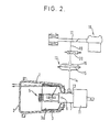
- reference 1 designates a body made of a synthetic resin.
- a lens 2 is mounted across a front opening of the body 1.
- Two reflectors 3 and 4 are contained in the body 1. These reflectors 3 and 4 have, respectively, reflective surfaces 3a and 4a comprising parabolic surfaces. These reflective surfaces 3a and 4a have been covered with aluminium, for example by plating or by evaporation.
- a high intensity discharge lamp 5 such as a small metal halide discharge lamp, is disposed at about the focus of the reflector 3 and is movable by virtue of a pivot pin 6 fixed to a base 7 of the discharge lamp 5.
- an incandescent lamp 8 such as a halogen lamp, is disposed at about the focus of the reflector 4 and is movable by virtue of a pivot pin 9 fixed to a base 10 of the lamp 8.
- Reference 11 designates a starting circuit of the headlamp unit.
- the discharge lamp 5 and the incandescent lamp 8 are operated so as to move together by way of a vacuum operated device 12 including a diaphragm 15. More particularly, the discharge lamp 5 and the lamp 8 are connected by a lever 13 which is attached to bases 7 and 10, the lever 13 being connected to a link 14, and this link 14 being connected to diaphragm 15.
- a chamber 16 in the device 12 is connected to an intake duct 17 of an engine 18 by way of a passage 19.
- the passage 19 can be opened and closed by an electromagnetic valve 20.
- the electromagnetic valve 20 is operated so as to open the passage 19 while the engine 18 is working, the diaphragm 15 is bent as is shown by a phantom line in Figure 2 owing to negative pressure in the chamber 16.
- Reference 30 designates an electric power source
- reference 31 designates a switch for two such headlamp units
- reference 32 designates a control circuit.
- the control circuit 32 includes a stepping-up circuit 33 and a ballast circuit 34.
- the stepping-up circuit 33 operates so as to raise the 12 V of the power source 30 to about 200 V which is necessary for the discharge lamps 5 of the headlamp units to light.
- the ballast circuit 34 operates so as to stabilise the voltage during the lighting of the discharge lamps 5.
- the control circuit 32 also includes a timer 35 which automatically stops the current supply to the lamps 8 when the discharge lamps 5 are lit stably.
- the starting circuits 11 operate so as to generate constitutional- age pulses of about 1,000 V to 10,000 V for starting the discharge lamps 5.
- the switch 31 When the switch 31 is turned on, voltage is supplied to the two discharge lamps 5 by way of the control circuit 32 and the two starting circuits 11, and also to the two lamps 8.
- the discharge lamps 5 and the lamps 8, therefore, begin to light. After starting of the discharge lamps 5, initially there is not a sufficient light output from them for driving because they are not stably lit. However, the lamps 8 begin to light stably from the start, as is known. Therefore, the lack of stable light output from the discharge lamps 5 for the initial period after lighting is compensated for by the lamps 8. It is possible, therefore, to drive immediately after switching on the headlamp units by using the light output of the lamps 8. From scores of seconds to several minutes after lighting of the discharge lamps 5, their output becomes stable and of sufficient level.
- the lamps 8 are de-energised via the timer 35 when the discharge lamps 5 have reached stable lighting and thereafter only the lamps 5 work as the light source of the headlamp units.
- lamps 8 operate as the lighting sources of the headlamp units until the discharge lamps 5 have reached stable lighting. Namely, the lamps 8 work so as to compensate for discharge lamps 5 until the latter have reached stable lighting.
- an incandescent lamp 8 can be used for a long time because it is used only during the period until a discharge lamp has reached stable lighting.
- a metal halide discharge lamp has essentially 3 - 5 times longer life compared to a halogen lamp, so using such a lamp there is provided a long life headlamp unit.
- a high beam and a low beam of the headlamp unit can be obtained freely by moving lamps 5 and 8.
- a high beam and a low beam can be obtained by moving case body 1 containing lamps 5 and 8 instead of lamps 5 and 8 themselves. More particularly it can be obtained by connecting link 14 of device 12 to case body 1 instead of lamp bases 7 and 10.
- solenoid means or oil pressure means etc.
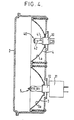
- FIG. 4 shows a further embodiment of the present invention.
- a high beam and a low beam can be obtained without moving mechanically lamps or case body.
- a high intensity discharge lamp 5 such as a small metal halide discharge lamp, is disposed at about the focus of a reflector 3 so as to have always a low beam.
- the discharge lamp 5 is connected to a starting circuit 11 by way of a base 7.
- An incandescent lamp 40 such as a halogen lamp 40, having two filaments, i.e. a low beam filament 41 and a high beam filament 42, is disposed at about the focus of a reflector 4.
- the lighting of the discharge lamp 5 and the lamp 40 is controlled by the lighting circuit shown in Figure 5.
- the lighting circuit is similar to that of the first embodiment.
- the low beam filaments 41 of two such lamps 40 (each being in a respective headlamp unit) are connected to a timer 35 and the high beam filaments 42 of the two lamps 40 are connected to an electric power source 30 by way of a switch 43 for a high beam.
- the discharge lamps 5 come to be used in place of the lamps 40 as a low beam illumination after the discharge lamps 5 are fit stably.
- a light sensor for switching off the lamps.
- a discharge lamp a small high pressure mercury lamp or a small high pressure sodium lamp could be used and the incandescent lamp could be of any suitable type, not necessarily a halogen lamp.
Landscapes
- Engineering & Computer Science (AREA)
- General Engineering & Computer Science (AREA)
- Non-Portable Lighting Devices Or Systems Thereof (AREA)
- Lighting Device Outwards From Vehicle And Optical Signal (AREA)
Claims (3)
Applications Claiming Priority (4)
| Application Number | Priority Date | Filing Date | Title |
|---|---|---|---|
| JP58006989A JPS59134022A (ja) | 1983-01-19 | 1983-01-19 | 車輌用前照灯装置 |
| JP6989/83 | 1983-01-19 | ||
| JP6988/83 | 1983-01-19 | ||
| JP58006988A JPS59134020A (ja) | 1983-01-19 | 1983-01-19 | 車輛用前照灯装置 |
Publications (4)
| Publication Number | Publication Date |
|---|---|
| EP0114742A2 EP0114742A2 (de) | 1984-08-01 |
| EP0114742A3 EP0114742A3 (en) | 1984-08-15 |
| EP0114742B1 EP0114742B1 (de) | 1986-12-30 |
| EP0114742B2 true EP0114742B2 (de) | 1989-12-27 |
Family
ID=26341210
Family Applications (1)
| Application Number | Title | Priority Date | Filing Date |
|---|---|---|---|
| EP84300284A Expired EP0114742B2 (de) | 1983-01-19 | 1984-01-18 | Scheinwerfer |
Country Status (3)
| Country | Link |
|---|---|
| US (1) | US4513357A (de) |
| EP (1) | EP0114742B2 (de) |
| DE (1) | DE3461859D1 (de) |
Families Citing this family (33)
| Publication number | Priority date | Publication date | Assignee | Title |
|---|---|---|---|---|
| FR2579721B1 (fr) * | 1985-03-26 | 1988-10-14 | Cibie Projecteurs | Ensemble d'eclairage de route a deux projecteurs pour vehicule automobile |
| DE3519611A1 (de) * | 1985-05-31 | 1986-12-04 | Patent-Treuhand-Gesellschaft für elektrische Glühlampen mbH, 8000 München | Kraftfahrzeugscheinwerfereinheit |
| JPS6293802A (ja) * | 1985-10-18 | 1987-04-30 | 東芝ライテック株式会社 | 車両用前照灯 |
| NL8600226A (nl) * | 1985-11-19 | 1987-06-16 | Philips Nv | Gesokkelde voertuig-koplamp. |
| JPS62198046A (ja) * | 1986-02-25 | 1987-09-01 | Nissan Motor Co Ltd | 車両用前照灯 |
| JP2691712B2 (ja) * | 1987-06-17 | 1997-12-17 | 日産自動車 株式会社 | プロジェクタ型の自動車用前照灯 |
| US4868458A (en) * | 1988-02-18 | 1989-09-19 | General Electric Company | Xenon lamp particularly suited for automotive applications |
| JPH0760603B2 (ja) * | 1989-07-19 | 1995-06-28 | 株式会社小糸製作所 | 車輌用前照灯 |
| DE3930746A1 (de) * | 1989-09-14 | 1991-03-28 | Hella Kg Hueck & Co | Scheinwerfer, insbesondere fuer kraftfahrzeuge |
| JPH03136938A (ja) * | 1989-10-23 | 1991-06-11 | Nissan Motor Co Ltd | 車両用放電灯ヘッドランプ装置 |
| JPH0793050B2 (ja) * | 1989-12-12 | 1995-10-09 | 株式会社小糸製作所 | 放電ランプ装置 |
| JP2592005B2 (ja) * | 1990-05-18 | 1997-03-19 | 株式会社小糸製作所 | 車輌用前照灯 |
| JPH0487846A (ja) * | 1990-07-31 | 1992-03-19 | Nissan Motor Co Ltd | 車両用ヘッドランプ装置 |
| FR2710131B1 (fr) * | 1993-09-15 | 1995-12-08 | Valeo Vision | Ensemble connecteur et générateur à haute tension pour une lampe à décharge de véhicule automobile. |
| JP3193604B2 (ja) * | 1995-12-25 | 2001-07-30 | 株式会社小糸製作所 | 放電バルブを有する車両用灯具 |
| DE19634750A1 (de) | 1996-08-28 | 1998-03-05 | Hella Kg Hueck & Co | Scheinwerfersystem für Kraftfahrzeuge |
| DE19710632A1 (de) * | 1997-03-14 | 1998-09-17 | Bosch Gmbh Robert | Scheinwerfer für Abblendlicht und Fernlicht für Fahrzeuge |
| JP3866383B2 (ja) * | 1997-07-30 | 2007-01-10 | 本田技研工業株式会社 | 自動二輪車の前照灯装置 |
| US6278382B1 (en) * | 1998-11-06 | 2001-08-21 | Demarco Ralph Anthony | Recognition/anti-collision light for aircraft |
| DE19956456A1 (de) * | 1999-11-24 | 2001-05-31 | Volkswagen Ag | Frontscheinwerfereinheit für Fahrzeuge |
| US6536918B1 (en) * | 2000-08-23 | 2003-03-25 | General Electric Company | Lighting system for generating pre-determined beam-pattern |
| JP3928691B2 (ja) * | 2000-12-06 | 2007-06-13 | 株式会社小糸製作所 | 車輌用前照灯 |
| JP3988466B2 (ja) * | 2002-01-17 | 2007-10-10 | スズキ株式会社 | 自動二輪車の2灯式ヘッドライト装置 |
| FR2836714B1 (fr) * | 2002-03-01 | 2004-10-22 | Holophane | Projecteur comprenant une lentille en verre et un support de lentille en matiere plastique et outil de surmoulage du support sur la lentille |
| US7553035B2 (en) * | 2002-05-07 | 2009-06-30 | Wright Greg J | Method and apparatus for constructing a perfect trough parabolic reflector |
| US7147348B2 (en) * | 2004-05-24 | 2006-12-12 | Hubbell Incorporated | Emergency lighting fixture having adjustable reflector and lamp assembly |
| US7093957B2 (en) * | 2004-05-24 | 2006-08-22 | Hubbell Incorporated | Adjustable double-arcuate reflector for an emergency lighting fixture |
| CN100478610C (zh) * | 2004-06-04 | 2009-04-15 | 吴国峰 | 节能灯具 |
| US20060077675A1 (en) * | 2004-10-12 | 2006-04-13 | Fleming Breton J | Automatic re-aim of headlights to improve beam patterns |
| JP2006216251A (ja) * | 2005-02-01 | 2006-08-17 | Koito Mfg Co Ltd | 車両用前照灯装置 |
| US20090251811A1 (en) * | 2005-06-21 | 2009-10-08 | Greg Wright | Method and Apparatus for Constructing a Perfect Trough Parabolic Reflector |
| CZ302547B6 (cs) * | 2005-07-04 | 2011-07-07 | Visteon Global Technologies, Inc. | Systém adaptivního predního osvetlení motorových vozidel |
| US11122652B2 (en) * | 2016-12-28 | 2021-09-14 | Lyle A. Simshaw | Windshield heating system |
Family Cites Families (19)
| Publication number | Priority date | Publication date | Assignee | Title |
|---|---|---|---|---|
| GB268046A (en) * | 1925-12-28 | 1927-03-28 | Eugene Victor Hayes Gratze | Improvements in fog penetrating lamps or lights for illuminating or signalling purposes |
| CH145553A (de) * | 1929-08-31 | 1931-02-28 | Inc Claude Neon Lights | Scheinwerfer. |
| US1950445A (en) * | 1930-10-21 | 1934-03-13 | Chester H Braselton | Lighting and ignition system for automobiles |
| US2259107A (en) * | 1938-08-13 | 1941-10-14 | Gen Electric | Luminaire |
| US2343822A (en) * | 1942-04-23 | 1944-03-07 | Holophane Co Inc | Lighting system and lighting unit for use therein |
| US2749482A (en) * | 1952-01-02 | 1956-06-05 | Fruengel Frank | Electric impulse lamp as transmitter for light-flash signaling system |
| CH347080A (it) * | 1956-03-10 | 1960-06-15 | Duilio Prof Torres | Impianto d'illuminazione di un automezzo, comprendente almeno un faro anabbagliante |
| CH349700A (de) * | 1956-08-10 | 1960-10-31 | B A G Bronzewarenfabrik Ag Tur | Elektrische Beleuchtungsarmatur |
| US3234421A (en) * | 1961-01-23 | 1966-02-08 | Gen Electric | Metallic halide electric discharge lamps |
| FR1295992A (fr) * | 1961-05-03 | 1962-06-15 | Projecteur d'éclairage émettant une lumière non éblouissante et éventuellement anti-brouillard | |
| GB1221946A (en) * | 1967-08-16 | 1971-02-10 | Lucas Industries Ltd | Sealed beam lamps |
| US3710097A (en) * | 1970-01-23 | 1973-01-09 | Lucas Industries Ltd | Headlamp assemblies |
| US3953726A (en) * | 1974-12-06 | 1976-04-27 | Scarritt Sr Frank M | Infinitely adjustable level light |
| US4029983A (en) * | 1976-03-25 | 1977-06-14 | Westinghouse Electric Corporation | Metal-halide discharge lamp having a light output with incandescent characteristics |
| JPS52157144U (de) * | 1976-05-24 | 1977-11-29 | ||
| US4345178A (en) | 1977-12-29 | 1982-08-17 | Gte Products Corporation | High intensity reflector lamp |
| JPS5559032A (en) * | 1978-10-20 | 1980-05-02 | Nippon Denso Co Ltd | Headlight optical axis controller for automobile |
| US4377841A (en) * | 1979-12-11 | 1983-03-22 | International Harvester Co. | High intensity discharge lighting system |
| NL8104948A (nl) * | 1981-11-02 | 1982-01-04 | Philips Nv | Halogeengloeilamp. |
-
1984
- 1984-01-17 US US06/571,492 patent/US4513357A/en not_active Expired - Lifetime
- 1984-01-18 DE DE8484300284T patent/DE3461859D1/de not_active Expired
- 1984-01-18 EP EP84300284A patent/EP0114742B2/de not_active Expired
Also Published As
| Publication number | Publication date |
|---|---|
| EP0114742B1 (de) | 1986-12-30 |
| US4513357A (en) | 1985-04-23 |
| DE3461859D1 (en) | 1987-02-05 |
| EP0114742A2 (de) | 1984-08-01 |
| EP0114742A3 (en) | 1984-08-15 |
Similar Documents
| Publication | Publication Date | Title |
|---|---|---|
| EP0114742B2 (de) | Scheinwerfer | |
| EP2684743B1 (de) | Fahrzeuglampe | |
| JP2001138799A (ja) | 車輌用照明装置 | |
| US4894585A (en) | Combination lamp | |
| JPH049692B2 (de) | ||
| JPH0338441A (ja) | 車輌用前照灯装置 | |
| US6913367B2 (en) | Vehicle headlamp | |
| KR20130138257A (ko) | 자동차 전조등의 광원을 직류로 구동하기 위한 방법 및 전기적 회로, 및 이러한 회로를 포함한 자동차 전조등의 광 모듈 및 이러한 광 모듈을 포함한 자동차 전조등 | |
| JP2019117724A (ja) | 車両用灯具 | |
| JPS59134022A (ja) | 車輌用前照灯装置 | |
| JPH0487846A (ja) | 車両用ヘッドランプ装置 | |
| US6260992B1 (en) | Vehicle headlamp device | |
| JP2004303634A (ja) | ヘッドランプ装置 | |
| JPS62292548A (ja) | 車輌用前照灯 | |
| US6715895B2 (en) | Luminaire body for a medical light, and the use thereof | |
| CA1244388A (en) | Headlamp unit | |
| JPS62292549A (ja) | 車輌用前照灯 | |
| KR200273368Y1 (ko) | 기계식과 전자식을 겸비한 긴급차량의 경광등 | |
| KR200309225Y1 (ko) | 차량용 전조등 | |
| KR200158507Y1 (ko) | 자동차의 헤드램프구조 | |
| KR19990005667U (ko) | 차량의 헤드라이트 자동 소등 장치 | |
| JPH0238846Y2 (de) | ||
| SU853283A1 (ru) | Лампа-фара | |
| JP2533311Y2 (ja) | 車輌用前照灯 | |
| JPH01289003A (ja) | 円筒状放電灯を光源とする自動車用灯具 |
Legal Events
| Date | Code | Title | Description |
|---|---|---|---|
| PUAI | Public reference made under article 153(3) epc to a published international application that has entered the european phase |
Free format text: ORIGINAL CODE: 0009012 |
|
| PUAL | Search report despatched |
Free format text: ORIGINAL CODE: 0009013 |
|
| 17P | Request for examination filed |
Effective date: 19840207 |
|
| AK | Designated contracting states |
Designated state(s): DE FR GB IT SE |
|
| AK | Designated contracting states |
Designated state(s): DE FR GB IT SE |
|
| RAP1 | Party data changed (applicant data changed or rights of an application transferred) |
Owner name: KABUSHIKI KAISHA TOSHIBA |
|
| GRAA | (expected) grant |
Free format text: ORIGINAL CODE: 0009210 |
|
| AK | Designated contracting states |
Kind code of ref document: B1 Designated state(s): DE FR GB IT SE |
|
| REF | Corresponds to: |
Ref document number: 3461859 Country of ref document: DE Date of ref document: 19870205 |
|
| ITF | It: translation for a ep patent filed | ||
| ET | Fr: translation filed | ||
| PLBI | Opposition filed |
Free format text: ORIGINAL CODE: 0009260 |
|
| 26 | Opposition filed |
Opponent name: N.V. PHILIPS' GLOEILAMPENFABRIEKEN Effective date: 19870928 |
|
| ITF | It: translation for a ep patent filed | ||
| PUAH | Patent maintained in amended form |
Free format text: ORIGINAL CODE: 0009272 |
|
| STAA | Information on the status of an ep patent application or granted ep patent |
Free format text: STATUS: PATENT MAINTAINED AS AMENDED |
|
| 27A | Patent maintained in amended form |
Effective date: 19891227 |
|
| AK | Designated contracting states |
Kind code of ref document: B2 Designated state(s): DE FR GB IT SE |
|
| ET3 | Fr: translation filed ** decision concerning opposition | ||
| ITTA | It: last paid annual fee | ||
| PGFP | Annual fee paid to national office [announced via postgrant information from national office to epo] |
Ref country code: GB Payment date: 19940110 Year of fee payment: 11 |
|
| PGFP | Annual fee paid to national office [announced via postgrant information from national office to epo] |
Ref country code: SE Payment date: 19940117 Year of fee payment: 11 |
|
| PG25 | Lapsed in a contracting state [announced via postgrant information from national office to epo] |
Ref country code: GB Effective date: 19950118 |
|
| PG25 | Lapsed in a contracting state [announced via postgrant information from national office to epo] |
Ref country code: SE Effective date: 19950119 |
|
| EAL | Se: european patent in force in sweden |
Ref document number: 84300284.1 |
|
| GBPC | Gb: european patent ceased through non-payment of renewal fee |
Effective date: 19950118 |
|
| EUG | Se: european patent has lapsed |
Ref document number: 84300284.1 |
|
| PGFP | Annual fee paid to national office [announced via postgrant information from national office to epo] |
Ref country code: DE Payment date: 19991231 Year of fee payment: 17 |
|
| PGFP | Annual fee paid to national office [announced via postgrant information from national office to epo] |
Ref country code: FR Payment date: 20000112 Year of fee payment: 17 |
|
| PG25 | Lapsed in a contracting state [announced via postgrant information from national office to epo] |
Ref country code: FR Free format text: LAPSE BECAUSE OF NON-PAYMENT OF DUE FEES Effective date: 20010928 |
|
| PG25 | Lapsed in a contracting state [announced via postgrant information from national office to epo] |
Ref country code: DE Free format text: LAPSE BECAUSE OF NON-PAYMENT OF DUE FEES Effective date: 20011101 |
|
| REG | Reference to a national code |
Ref country code: FR Ref legal event code: ST |