EP0114742B2 - A headlamp unit - Google Patents
A headlamp unit Download PDFInfo
- Publication number
- EP0114742B2 EP0114742B2 EP84300284A EP84300284A EP0114742B2 EP 0114742 B2 EP0114742 B2 EP 0114742B2 EP 84300284 A EP84300284 A EP 84300284A EP 84300284 A EP84300284 A EP 84300284A EP 0114742 B2 EP0114742 B2 EP 0114742B2
- Authority
- EP
- European Patent Office
- Prior art keywords
- lamps
- lamp
- low beam
- discharge
- lighting
- Prior art date
- Legal status (The legal status is an assumption and is not a legal conclusion. Google has not performed a legal analysis and makes no representation as to the accuracy of the status listed.)
- Expired
Links
- 229910052736 halogen Inorganic materials 0.000 description 5
- 150000002367 halogens Chemical class 0.000 description 5
- 238000005286 illumination Methods 0.000 description 5
- 229910001507 metal halide Inorganic materials 0.000 description 4
- 150000005309 metal halides Chemical class 0.000 description 4
- 238000010276 construction Methods 0.000 description 2
- 238000010586 diagram Methods 0.000 description 2
- QSHDDOUJBYECFT-UHFFFAOYSA-N mercury Chemical compound [Hg] QSHDDOUJBYECFT-UHFFFAOYSA-N 0.000 description 2
- 229910052753 mercury Inorganic materials 0.000 description 2
- DGAQECJNVWCQMB-PUAWFVPOSA-M Ilexoside XXIX Chemical compound C[C@@H]1CC[C@@]2(CC[C@@]3(C(=CC[C@H]4[C@]3(CC[C@@H]5[C@@]4(CC[C@@H](C5(C)C)OS(=O)(=O)[O-])C)C)[C@@H]2[C@]1(C)O)C)C(=O)O[C@H]6[C@@H]([C@H]([C@@H]([C@H](O6)CO)O)O)O.[Na+] DGAQECJNVWCQMB-PUAWFVPOSA-M 0.000 description 1
- 239000004411 aluminium Substances 0.000 description 1
- 229910052782 aluminium Inorganic materials 0.000 description 1
- XAGFODPZIPBFFR-UHFFFAOYSA-N aluminium Chemical compound [Al] XAGFODPZIPBFFR-UHFFFAOYSA-N 0.000 description 1
- 238000010891 electric arc Methods 0.000 description 1
- 230000008020 evaporation Effects 0.000 description 1
- 238000001704 evaporation Methods 0.000 description 1
- 238000007747 plating Methods 0.000 description 1
- 229910052708 sodium Inorganic materials 0.000 description 1
- 239000011734 sodium Substances 0.000 description 1
- 229920003002 synthetic resin Polymers 0.000 description 1
- 239000000057 synthetic resin Substances 0.000 description 1
- WFKWXMTUELFFGS-UHFFFAOYSA-N tungsten Chemical compound [W] WFKWXMTUELFFGS-UHFFFAOYSA-N 0.000 description 1
Images


Classifications
-
- F—MECHANICAL ENGINEERING; LIGHTING; HEATING; WEAPONS; BLASTING
- F21—LIGHTING
- F21S—NON-PORTABLE LIGHTING DEVICES; SYSTEMS THEREOF; VEHICLE LIGHTING DEVICES SPECIALLY ADAPTED FOR VEHICLE EXTERIORS
- F21S41/00—Illuminating devices specially adapted for vehicle exteriors, e.g. headlamps
- F21S41/60—Illuminating devices specially adapted for vehicle exteriors, e.g. headlamps characterised by a variable light distribution
- F21S41/65—Illuminating devices specially adapted for vehicle exteriors, e.g. headlamps characterised by a variable light distribution by acting on light sources
- F21S41/657—Illuminating devices specially adapted for vehicle exteriors, e.g. headlamps characterised by a variable light distribution by acting on light sources by moving light sources
-
- F—MECHANICAL ENGINEERING; LIGHTING; HEATING; WEAPONS; BLASTING
- F21—LIGHTING
- F21S—NON-PORTABLE LIGHTING DEVICES; SYSTEMS THEREOF; VEHICLE LIGHTING DEVICES SPECIALLY ADAPTED FOR VEHICLE EXTERIORS
- F21S41/00—Illuminating devices specially adapted for vehicle exteriors, e.g. headlamps
- F21S41/10—Illuminating devices specially adapted for vehicle exteriors, e.g. headlamps characterised by the light source
- F21S41/14—Illuminating devices specially adapted for vehicle exteriors, e.g. headlamps characterised by the light source characterised by the type of light source
- F21S41/17—Discharge light sources
- F21S41/172—High-intensity discharge light sources
-
- F—MECHANICAL ENGINEERING; LIGHTING; HEATING; WEAPONS; BLASTING
- F21—LIGHTING
- F21S—NON-PORTABLE LIGHTING DEVICES; SYSTEMS THEREOF; VEHICLE LIGHTING DEVICES SPECIALLY ADAPTED FOR VEHICLE EXTERIORS
- F21S41/00—Illuminating devices specially adapted for vehicle exteriors, e.g. headlamps
- F21S41/10—Illuminating devices specially adapted for vehicle exteriors, e.g. headlamps characterised by the light source
- F21S41/19—Attachment of light sources or lamp holders
- F21S41/192—Details of lamp holders, terminals or connectors
-
- Y—GENERAL TAGGING OF NEW TECHNOLOGICAL DEVELOPMENTS; GENERAL TAGGING OF CROSS-SECTIONAL TECHNOLOGIES SPANNING OVER SEVERAL SECTIONS OF THE IPC; TECHNICAL SUBJECTS COVERED BY FORMER USPC CROSS-REFERENCE ART COLLECTIONS [XRACs] AND DIGESTS
- Y10—TECHNICAL SUBJECTS COVERED BY FORMER USPC
- Y10S—TECHNICAL SUBJECTS COVERED BY FORMER USPC CROSS-REFERENCE ART COLLECTIONS [XRACs] AND DIGESTS
- Y10S362/00—Illumination
- Y10S362/802—Position or condition responsive switch
Definitions
- the present invention generally relates to a vehicle headlamp unit.
- Incandescent lamps including halogen lamps, having a filament made of a tungsten wire, are widely used as light sources in headlamp units for automobiles. These lamps, however, are of low efficiency and of short life. The filaments are easily broken due to vibration, and it is troublesome to change lamps frequently. Moreover, there is a demand for a headlamp unit having a higher light output.
- An object of the present invention is to provide a headlamp unit compensating for a lack of light output of a high intensity discharge lamp after lighting by using an incandescent lamp.
- a vehicle headlamp unit comprising the features of claim 1.
- Particular embodiments of the invention are given in claims 2 and 3.
- reference 1 designates a body made of a synthetic resin.
- a lens 2 is mounted across a front opening of the body 1.
- Two reflectors 3 and 4 are contained in the body 1. These reflectors 3 and 4 have, respectively, reflective surfaces 3a and 4a comprising parabolic surfaces. These reflective surfaces 3a and 4a have been covered with aluminium, for example by plating or by evaporation.
- a high intensity discharge lamp 5 such as a small metal halide discharge lamp, is disposed at about the focus of the reflector 3 and is movable by virtue of a pivot pin 6 fixed to a base 7 of the discharge lamp 5.
- an incandescent lamp 8 such as a halogen lamp, is disposed at about the focus of the reflector 4 and is movable by virtue of a pivot pin 9 fixed to a base 10 of the lamp 8.
- Reference 11 designates a starting circuit of the headlamp unit.
- the discharge lamp 5 and the incandescent lamp 8 are operated so as to move together by way of a vacuum operated device 12 including a diaphragm 15. More particularly, the discharge lamp 5 and the lamp 8 are connected by a lever 13 which is attached to bases 7 and 10, the lever 13 being connected to a link 14, and this link 14 being connected to diaphragm 15.
- a chamber 16 in the device 12 is connected to an intake duct 17 of an engine 18 by way of a passage 19.
- the passage 19 can be opened and closed by an electromagnetic valve 20.
- the electromagnetic valve 20 is operated so as to open the passage 19 while the engine 18 is working, the diaphragm 15 is bent as is shown by a phantom line in Figure 2 owing to negative pressure in the chamber 16.
- Reference 30 designates an electric power source
- reference 31 designates a switch for two such headlamp units
- reference 32 designates a control circuit.
- the control circuit 32 includes a stepping-up circuit 33 and a ballast circuit 34.
- the stepping-up circuit 33 operates so as to raise the 12 V of the power source 30 to about 200 V which is necessary for the discharge lamps 5 of the headlamp units to light.
- the ballast circuit 34 operates so as to stabilise the voltage during the lighting of the discharge lamps 5.
- the control circuit 32 also includes a timer 35 which automatically stops the current supply to the lamps 8 when the discharge lamps 5 are lit stably.
- the starting circuits 11 operate so as to generate constitutional- age pulses of about 1,000 V to 10,000 V for starting the discharge lamps 5.
- the switch 31 When the switch 31 is turned on, voltage is supplied to the two discharge lamps 5 by way of the control circuit 32 and the two starting circuits 11, and also to the two lamps 8.
- the discharge lamps 5 and the lamps 8, therefore, begin to light. After starting of the discharge lamps 5, initially there is not a sufficient light output from them for driving because they are not stably lit. However, the lamps 8 begin to light stably from the start, as is known. Therefore, the lack of stable light output from the discharge lamps 5 for the initial period after lighting is compensated for by the lamps 8. It is possible, therefore, to drive immediately after switching on the headlamp units by using the light output of the lamps 8. From scores of seconds to several minutes after lighting of the discharge lamps 5, their output becomes stable and of sufficient level.
- the lamps 8 are de-energised via the timer 35 when the discharge lamps 5 have reached stable lighting and thereafter only the lamps 5 work as the light source of the headlamp units.
- lamps 8 operate as the lighting sources of the headlamp units until the discharge lamps 5 have reached stable lighting. Namely, the lamps 8 work so as to compensate for discharge lamps 5 until the latter have reached stable lighting.
- an incandescent lamp 8 can be used for a long time because it is used only during the period until a discharge lamp has reached stable lighting.
- a metal halide discharge lamp has essentially 3 - 5 times longer life compared to a halogen lamp, so using such a lamp there is provided a long life headlamp unit.
- a high beam and a low beam of the headlamp unit can be obtained freely by moving lamps 5 and 8.
- a high beam and a low beam can be obtained by moving case body 1 containing lamps 5 and 8 instead of lamps 5 and 8 themselves. More particularly it can be obtained by connecting link 14 of device 12 to case body 1 instead of lamp bases 7 and 10.
- solenoid means or oil pressure means etc.
- FIG. 4 shows a further embodiment of the present invention.
- a high beam and a low beam can be obtained without moving mechanically lamps or case body.
- a high intensity discharge lamp 5 such as a small metal halide discharge lamp, is disposed at about the focus of a reflector 3 so as to have always a low beam.
- the discharge lamp 5 is connected to a starting circuit 11 by way of a base 7.
- An incandescent lamp 40 such as a halogen lamp 40, having two filaments, i.e. a low beam filament 41 and a high beam filament 42, is disposed at about the focus of a reflector 4.
- the lighting of the discharge lamp 5 and the lamp 40 is controlled by the lighting circuit shown in Figure 5.
- the lighting circuit is similar to that of the first embodiment.
- the low beam filaments 41 of two such lamps 40 (each being in a respective headlamp unit) are connected to a timer 35 and the high beam filaments 42 of the two lamps 40 are connected to an electric power source 30 by way of a switch 43 for a high beam.
- the discharge lamps 5 come to be used in place of the lamps 40 as a low beam illumination after the discharge lamps 5 are fit stably.
- a light sensor for switching off the lamps.
- a discharge lamp a small high pressure mercury lamp or a small high pressure sodium lamp could be used and the incandescent lamp could be of any suitable type, not necessarily a halogen lamp.
Landscapes
- Engineering & Computer Science (AREA)
- General Engineering & Computer Science (AREA)
- Lighting Device Outwards From Vehicle And Optical Signal (AREA)
- Non-Portable Lighting Devices Or Systems Thereof (AREA)
Description
- The present invention generally relates to a vehicle headlamp unit.
- Incandescent lamps (including halogen lamps), having a filament made of a tungsten wire, are widely used as light sources in headlamp units for automobiles. These lamps, however, are of low efficiency and of short life. The filaments are easily broken due to vibration, and it is troublesome to change lamps frequently. Moreover, there is a demand for a headlamp unit having a higher light output.
- It has been considered, therefore to use high intensity discharge lamps, e.g. small metal halide discharge lamps, having high lumen efficiency and long life compared with incandescent lamps (see, for instance, DE-C-889 806). However, it is well known that it takes a long time, from about scores of seconds to several minutes, for such a high intensity discharge lamp to achieve stable lighting. This starting problem is known from DE-U-1 792 675 and US-A-2 259 107 with reference to mercury discharge lamps.
- It is known for commercial aircraft for landings at night to use high intensity lamps using an arc discharge as shown in United States Patent No. 4 345 178. It is easy to use such lamps only for general lighting.
- However, if such high intensity discharge lamps are used on motor vehicles, especially automobiles, there cannot be obtained sufficient light output for safety immediately after lighting such a lamp. It is necessary to wait more than scores of seconds for safety after lighting when only such lamps are used.
- Moreover, as is known, it is necessary for two kinds of beams to be available in a headlamp, i. e. a high beam and a low (dipped) beam. It is therefore, necessary to be able to change freely these two beams as occasion calls.
- As prior art there can also be mentioned US-A-1 950 445 and GB-A-268 046.
- An object of the present invention is to provide a headlamp unit compensating for a lack of light output of a high intensity discharge lamp after lighting by using an incandescent lamp.
- According to the present invention, there is provided a vehicle headlamp unit comprising the features of claim 1. Particular embodiments of the invention are given in
claims - The present invention will now be described, by way of example, with reference to the accompanying drawings, in which:
- Figure 1 is a transverse sectional view of a headlamp unit;
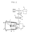
- Figure 2 is a sectional view taken on the line 11-11 of Figure 1;
- Figure 3 is a schematic diagram of a circuit using the headlamp unit of Figure 1;
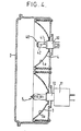
- Figure 4 is a transverse sectional view of an alternative embodiment to that of Figure 1; and
- Figure 5 is a schematic diagram of a circuit using the headlamp unit of Figure 4.
- Throughout the drawings, like reference numerals designate identical or corresponding parts throughout the several views.
- Referring first to Figures 1, 2 and 3, reference 1 designates a body made of a synthetic resin. A
lens 2 is mounted across a front opening of the body 1. Tworeflectors reflectors reflective surfaces 3a and 4a comprising parabolic surfaces. Thesereflective surfaces 3a and 4a have been covered with aluminium, for example by plating or by evaporation. In thereflector 3, a high intensity discharge lamp 5, such as a small metal halide discharge lamp, is disposed at about the focus of thereflector 3 and is movable by virtue of a pivot pin 6 fixed to a base 7 of the discharge lamp 5. In thereflector 4, an incandescent lamp 8, such as a halogen lamp, is disposed at about the focus of thereflector 4 and is movable by virtue of a pivot pin 9 fixed to abase 10 of the lamp 8.Reference 11 designates a starting circuit of the headlamp unit. - The discharge lamp 5 and the incandescent lamp 8 are operated so as to move together by way of a vacuum operated
device 12 including adiaphragm 15. More particularly, the discharge lamp 5 and the lamp 8 are connected by alever 13 which is attached tobases 7 and 10, thelever 13 being connected to alink 14, and thislink 14 being connected todiaphragm 15. Achamber 16 in thedevice 12 is connected to an intake duct 17 of anengine 18 by way of apassage 19. Thepassage 19 can be opened and closed by anelectromagnetic valve 20. When theelectromagnetic valve 20 is operated so as to open thepassage 19 while theengine 18 is working, thediaphragm 15 is bent as is shown by a phantom line in Figure 2 owing to negative pressure in thechamber 16. Thelever 13, therefore, is lifted up by way of thelink 14, so that the discharge lamp 5 and the lamp 8 are tilted a little about the pivot pins 6 and 9 respectively. As is shown in phantom lines in Figure 2, the reflected beam of the discharge lamp 5 becomes a high beam. The lamp 8 moves with the lamp 5 so, the reflected beams of both lamps 5 and 8 are directed in the same direction, i.e. both can provide a high beam and both can provide a low beam. - The lighting situation with the above construction is controlled by the lighting circuit shown in Figure 3.
Reference 30 designates an electric power source,reference 31 designates a switch for two such headlamp units andreference 32 designates a control circuit. Thecontrol circuit 32 includes a stepping-upcircuit 33 and aballast circuit 34. The stepping-upcircuit 33 operates so as to raise the 12 V of thepower source 30 to about 200 V which is necessary for the discharge lamps 5 of the headlamp units to light. Theballast circuit 34 operates so as to stabilise the voltage during the lighting of the discharge lamps 5. Thecontrol circuit 32 also includes atimer 35 which automatically stops the current supply to the lamps 8 when the discharge lamps 5 are lit stably. Thestarting circuits 11 operate so as to generate voit- age pulses of about 1,000 V to 10,000 V for starting the discharge lamps 5. - When the
switch 31 is turned on, voltage is supplied to the two discharge lamps 5 by way of thecontrol circuit 32 and the twostarting circuits 11, and also to the two lamps 8. The discharge lamps 5 and the lamps 8, therefore, begin to light. After starting of the discharge lamps 5, initially there is not a sufficient light output from them for driving because they are not stably lit. However, the lamps 8 begin to light stably from the start, as is known. Therefore, the lack of stable light output from the discharge lamps 5 for the initial period after lighting is compensated for by the lamps 8. It is possible, therefore, to drive immediately after switching on the headlamp units by using the light output of the lamps 8. From scores of seconds to several minutes after lighting of the discharge lamps 5, their output becomes stable and of sufficient level. The lamps 8 are de-energised via thetimer 35 when the discharge lamps 5 have reached stable lighting and thereafter only the lamps 5 work as the light source of the headlamp units. - When it is necessary to have a low beam immediately after lighting, it can be obtained by closing the
passage 19 by theelectromagnetic valve 20. When it is necessary to have a high beam (as is shown in phantom lines in Figure 2) immediately after lighting, it can be obtained by achieving a negative pressure in thechamber 16, as aforementioned, by opening thepassage 19 by theelectromagnetic valve 20. In both cases, lamps 8 operate as the lighting sources of the headlamp units until the discharge lamps 5 have reached stable lighting. Namely, the lamps 8 work so as to compensate for discharge lamps 5 until the latter have reached stable lighting. - According to the above embodiment, an incandescent lamp 8 can be used for a long time because it is used only during the period until a discharge lamp has reached stable lighting. A metal halide discharge lamp has essentially 3 - 5 times longer life compared to a halogen lamp, so using such a lamp there is provided a long life headlamp unit. Moreover a high beam and a low beam of the headlamp unit can be obtained freely by moving lamps 5 and 8.
- There could be used one reflector body having two reflectors instead of two independent reflectors. Moreover, a high beam and a low beam can be obtained by moving case body 1 containing lamps 5 and 8 instead of lamps 5 and 8 themselves. More particularly it can be obtained by connecting
link 14 ofdevice 12 to case body 1 instead oflamp bases 7 and 10. As an alternative means for moving lamps or a case body, there may be used solenoid means or oil pressure means, etc. - Figure 4 shows a further embodiment of the present invention. In this embodiment, a high beam and a low beam can be obtained without moving mechanically lamps or case body. A high intensity discharge lamp 5 such as a small metal halide discharge lamp, is disposed at about the focus of a
reflector 3 so as to have always a low beam. The discharge lamp 5 is connected to a startingcircuit 11 by way of a base 7. Anincandescent lamp 40, such as ahalogen lamp 40, having two filaments, i.e. alow beam filament 41 and ahigh beam filament 42, is disposed at about the focus of areflector 4. - The lighting of the discharge lamp 5 and the
lamp 40 is controlled by the lighting circuit shown in Figure 5. The lighting circuit is similar to that of the first embodiment. Thelow beam filaments 41 of two such lamps 40 (each being in a respective headlamp unit) are connected to atimer 35 and thehigh beam filaments 42 of the twolamps 40 are connected to anelectric power source 30 by way of aswitch 43 for a high beam. - In such a construction, when a low beam is necessary the discharge lamps 5 begin to light and the
low beam filaments 41 of thelamps 40 light by turning on theswitch 31. A sufficiently bright low beam cannot be obtained after lighting only with the discharge lamps 5, but thelow beam filaments 41, however, light immediately after turning on theswitch 31 and a sufficiently bright low beam is obtained for driving. When the discharge lamps 5 are lit stably (i.e. with a sufficiently bright and stable low beam for driving), thefilaments 41 are de-energised by thetimer 35. After that, the discharge lamps 5 work for a low beam only. When it is necessaryto have a high beam in this situation, it can be obtained by usinghigh beam filaments 42 of thelamps 40, more particularly by adding to the low beam illumination of the discharge lamps 5 a high beam illumination from thelamps 40. - Moreover, when it is necessary to have a high beam immediately after lighting, it can be obtained by using only the
lamps 40 without the discharge lamps 5, more particularly by adding to the low beam illumination of the low beam filaments 41 a high beam illumination from thehigh beam filaments 42. The discharge lamps 5 come to be used in place of thelamps 40 as a low beam illumination after the discharge lamps 5 are fit stably. - There could be used a light sensor for switching off the lamps. Moreover, as a discharge lamp a small high pressure mercury lamp or a small high pressure sodium lamp could be used and the incandescent lamp could be of any suitable type, not necessarily a halogen lamp.
Claims (3)
Applications Claiming Priority (4)
| Application Number | Priority Date | Filing Date | Title |
|---|---|---|---|
| JP58006989A JPS59134022A (en) | 1983-01-19 | 1983-01-19 | Headlight device for vehicle |
| JP6989/83 | 1983-01-19 | ||
| JP6988/83 | 1983-01-19 | ||
| JP58006988A JPS59134020A (en) | 1983-01-19 | 1983-01-19 | Vehicle headlight device |
Publications (4)
| Publication Number | Publication Date |
|---|---|
| EP0114742A2 EP0114742A2 (en) | 1984-08-01 |
| EP0114742A3 EP0114742A3 (en) | 1984-08-15 |
| EP0114742B1 EP0114742B1 (en) | 1986-12-30 |
| EP0114742B2 true EP0114742B2 (en) | 1989-12-27 |
Family
ID=26341210
Family Applications (1)
| Application Number | Title | Priority Date | Filing Date |
|---|---|---|---|
| EP84300284A Expired EP0114742B2 (en) | 1983-01-19 | 1984-01-18 | A headlamp unit |
Country Status (3)
| Country | Link |
|---|---|
| US (1) | US4513357A (en) |
| EP (1) | EP0114742B2 (en) |
| DE (1) | DE3461859D1 (en) |
Families Citing this family (33)
| Publication number | Priority date | Publication date | Assignee | Title |
|---|---|---|---|---|
| FR2579721B1 (en) * | 1985-03-26 | 1988-10-14 | Cibie Projecteurs | TWO PROJECTOR ROAD LIGHTING ASSEMBLY FOR MOTOR VEHICLE |
| DE3519611A1 (en) * | 1985-05-31 | 1986-12-04 | Patent-Treuhand-Gesellschaft für elektrische Glühlampen mbH, 8000 München | MOTOR VEHICLE HEADLAMP UNIT |
| JPS6293802A (en) * | 1985-10-18 | 1987-04-30 | 東芝ライテック株式会社 | Head lamp for vehicle |
| NL8600226A (en) * | 1985-11-19 | 1987-06-16 | Philips Nv | DOCKED VEHICLE HEADLIGHT. |
| JPS62198046A (en) * | 1986-02-25 | 1987-09-01 | Nissan Motor Co Ltd | Head light for vehicle |
| JP2691712B2 (en) * | 1987-06-17 | 1997-12-17 | 日産自動車 株式会社 | Projector type vehicle headlight |
| US4868458A (en) * | 1988-02-18 | 1989-09-19 | General Electric Company | Xenon lamp particularly suited for automotive applications |
| JPH0760603B2 (en) * | 1989-07-19 | 1995-06-28 | 株式会社小糸製作所 | Vehicle headlights |
| DE3930746A1 (en) * | 1989-09-14 | 1991-03-28 | Hella Kg Hueck & Co | HEADLIGHTS, ESPECIALLY FOR MOTOR VEHICLES |
| JPH03136938A (en) * | 1989-10-23 | 1991-06-11 | Nissan Motor Co Ltd | Discharge lamp head lamp device for vehicle |
| JPH0793050B2 (en) * | 1989-12-12 | 1995-10-09 | 株式会社小糸製作所 | Discharge lamp device |
| JP2592005B2 (en) * | 1990-05-18 | 1997-03-19 | 株式会社小糸製作所 | Vehicle headlights |
| JPH0487846A (en) * | 1990-07-31 | 1992-03-19 | Nissan Motor Co Ltd | Head lamp device for vehicle |
| FR2710131B1 (en) * | 1993-09-15 | 1995-12-08 | Valeo Vision | High voltage connector and generator assembly for a motor vehicle discharge lamp. |
| JP3193604B2 (en) * | 1995-12-25 | 2001-07-30 | 株式会社小糸製作所 | Vehicle lamp having a discharge bulb |
| DE19634750A1 (en) | 1996-08-28 | 1998-03-05 | Hella Kg Hueck & Co | Headlight system for motor vehicles |
| DE19710632A1 (en) * | 1997-03-14 | 1998-09-17 | Bosch Gmbh Robert | Vehicle headlamp for full beam and dipped beam |
| JP3866383B2 (en) | 1997-07-30 | 2007-01-10 | 本田技研工業株式会社 | Motorcycle headlamp device |
| US6278382B1 (en) * | 1998-11-06 | 2001-08-21 | Demarco Ralph Anthony | Recognition/anti-collision light for aircraft |
| DE19956456A1 (en) * | 1999-11-24 | 2001-05-31 | Volkswagen Ag | Headlight unit for vehicles comprises a second headlight incorporating a transparent element which has a light source at its rear end and is housed in a hollow component with a second light source |
| US6536918B1 (en) * | 2000-08-23 | 2003-03-25 | General Electric Company | Lighting system for generating pre-determined beam-pattern |
| JP3928691B2 (en) * | 2000-12-06 | 2007-06-13 | 株式会社小糸製作所 | Vehicle headlamp |
| JP3988466B2 (en) * | 2002-01-17 | 2007-10-10 | スズキ株式会社 | Two-light headlight device for motorcycles |
| FR2836714B1 (en) * | 2002-03-01 | 2004-10-22 | Holophane | HEADLIGHT COMPRISING A GLASS LENS AND A PLASTIC LENS SUPPORT AND TOOL FOR OVERMOLDING THE SUPPORT ON THE LENS |
| US7553035B2 (en) * | 2002-05-07 | 2009-06-30 | Wright Greg J | Method and apparatus for constructing a perfect trough parabolic reflector |
| US7147348B2 (en) * | 2004-05-24 | 2006-12-12 | Hubbell Incorporated | Emergency lighting fixture having adjustable reflector and lamp assembly |
| US7093957B2 (en) * | 2004-05-24 | 2006-08-22 | Hubbell Incorporated | Adjustable double-arcuate reflector for an emergency lighting fixture |
| CN100478610C (en) * | 2004-06-04 | 2009-04-15 | 吴国峰 | Energy-saving lamp |
| US20060077675A1 (en) * | 2004-10-12 | 2006-04-13 | Fleming Breton J | Automatic re-aim of headlights to improve beam patterns |
| JP2006216251A (en) * | 2005-02-01 | 2006-08-17 | Koito Mfg Co Ltd | Vehicle headlamp device |
| US20090251811A1 (en) * | 2005-06-21 | 2009-10-08 | Greg Wright | Method and Apparatus for Constructing a Perfect Trough Parabolic Reflector |
| CZ302547B6 (en) * | 2005-07-04 | 2011-07-07 | Visteon Global Technologies, Inc. | Adaptive headlight system of motor vehicles |
| US11122652B2 (en) * | 2016-12-28 | 2021-09-14 | Lyle A. Simshaw | Windshield heating system |
Family Cites Families (19)
| Publication number | Priority date | Publication date | Assignee | Title |
|---|---|---|---|---|
| GB268046A (en) * | 1925-12-28 | 1927-03-28 | Eugene Victor Hayes Gratze | Improvements in fog penetrating lamps or lights for illuminating or signalling purposes |
| CH145553A (en) * | 1929-08-31 | 1931-02-28 | Inc Claude Neon Lights | Headlights. |
| US1950445A (en) * | 1930-10-21 | 1934-03-13 | Chester H Braselton | Lighting and ignition system for automobiles |
| US2259107A (en) * | 1938-08-13 | 1941-10-14 | Gen Electric | Luminaire |
| US2343822A (en) * | 1942-04-23 | 1944-03-07 | Holophane Co Inc | Lighting system and lighting unit for use therein |
| US2749482A (en) * | 1952-01-02 | 1956-06-05 | Fruengel Frank | Electric impulse lamp as transmitter for light-flash signaling system |
| CH347080A (en) * | 1956-03-10 | 1960-06-15 | Duilio Prof Torres | Lighting system of a motor vehicle, comprising at least one dipped beam headlight |
| CH349700A (en) * | 1956-08-10 | 1960-10-31 | B A G Bronzewarenfabrik Ag Tur | Electric lighting fixture |
| US3234421A (en) * | 1961-01-23 | 1966-02-08 | Gen Electric | Metallic halide electric discharge lamps |
| FR1295992A (en) * | 1961-05-03 | 1962-06-15 | Lighting projector emitting a glare-free light and possibly anti-fog | |
| GB1221946A (en) * | 1967-08-16 | 1971-02-10 | Lucas Industries Ltd | Sealed beam lamps |
| US3710097A (en) * | 1970-01-23 | 1973-01-09 | Lucas Industries Ltd | Headlamp assemblies |
| US3953726A (en) * | 1974-12-06 | 1976-04-27 | Scarritt Sr Frank M | Infinitely adjustable level light |
| US4029983A (en) * | 1976-03-25 | 1977-06-14 | Westinghouse Electric Corporation | Metal-halide discharge lamp having a light output with incandescent characteristics |
| JPS52157144U (en) * | 1976-05-24 | 1977-11-29 | ||
| US4345178A (en) | 1977-12-29 | 1982-08-17 | Gte Products Corporation | High intensity reflector lamp |
| JPS5559032A (en) * | 1978-10-20 | 1980-05-02 | Nippon Denso Co Ltd | Headlight optical axis controller for automobile |
| US4377841A (en) * | 1979-12-11 | 1983-03-22 | International Harvester Co. | High intensity discharge lighting system |
| NL8104948A (en) * | 1981-11-02 | 1982-01-04 | Philips Nv | Halogen filled double filament lamp - has three support wires within quartz glass envelope, each connected to current supply foil and terminal wire |
-
1984
- 1984-01-17 US US06/571,492 patent/US4513357A/en not_active Expired - Lifetime
- 1984-01-18 EP EP84300284A patent/EP0114742B2/en not_active Expired
- 1984-01-18 DE DE8484300284T patent/DE3461859D1/en not_active Expired
Also Published As
| Publication number | Publication date |
|---|---|
| EP0114742B1 (en) | 1986-12-30 |
| EP0114742A2 (en) | 1984-08-01 |
| DE3461859D1 (en) | 1987-02-05 |
| EP0114742A3 (en) | 1984-08-15 |
| US4513357A (en) | 1985-04-23 |
Similar Documents
| Publication | Publication Date | Title |
|---|---|---|
| EP0114742B2 (en) | A headlamp unit | |
| EP2684743B1 (en) | Vehicle lamp | |
| JP2001135109A (en) | Incandescent lamp | |
| US4894585A (en) | Combination lamp | |
| JPS59134020A (en) | Vehicle headlight device | |
| JPH0338441A (en) | Head lamp for vehicle | |
| US6913367B2 (en) | Vehicle headlamp | |
| KR20130138257A (en) | Method and electrical circuit for operating a light source of a motor vehicle headlight with direct current, and light module of a motor vehicle headlight comprising such a circuit and motor vehicle headlight comprising such a light module | |
| JP2019117724A (en) | Vehicular lighting fixture | |
| JPS59134022A (en) | Headlight device for vehicle | |
| JPH0487846A (en) | Head lamp device for vehicle | |
| HU186083B (en) | System of automobile headlights | |
| US6260992B1 (en) | Vehicle headlamp device | |
| JP2004303634A (en) | Headlamp device | |
| JPS62292548A (en) | Headlight for vehicle | |
| US6715895B2 (en) | Luminaire body for a medical light, and the use thereof | |
| CA1244388A (en) | Headlamp unit | |
| JPS62292549A (en) | vehicle headlights | |
| KR200273368Y1 (en) | An emergency lamp for an ambulance which includes a analog system and a digital system | |
| KR200309225Y1 (en) | Head light of vehicle | |
| KR200158507Y1 (en) | Head lamp structure of a car | |
| KR19990005667U (en) | Vehicle headlight auto-off | |
| KR910001125Y1 (en) | Headlights for vehicles | |
| JPH0238846Y2 (en) | ||
| SU853283A1 (en) | Lamp-headlight |
Legal Events
| Date | Code | Title | Description |
|---|---|---|---|
| PUAI | Public reference made under article 153(3) epc to a published international application that has entered the european phase |
Free format text: ORIGINAL CODE: 0009012 |
|
| PUAL | Search report despatched |
Free format text: ORIGINAL CODE: 0009013 |
|
| 17P | Request for examination filed |
Effective date: 19840207 |
|
| AK | Designated contracting states |
Designated state(s): DE FR GB IT SE |
|
| AK | Designated contracting states |
Designated state(s): DE FR GB IT SE |
|
| RAP1 | Party data changed (applicant data changed or rights of an application transferred) |
Owner name: KABUSHIKI KAISHA TOSHIBA |
|
| GRAA | (expected) grant |
Free format text: ORIGINAL CODE: 0009210 |
|
| AK | Designated contracting states |
Kind code of ref document: B1 Designated state(s): DE FR GB IT SE |
|
| REF | Corresponds to: |
Ref document number: 3461859 Country of ref document: DE Date of ref document: 19870205 |
|
| ITF | It: translation for a ep patent filed | ||
| ET | Fr: translation filed | ||
| PLBI | Opposition filed |
Free format text: ORIGINAL CODE: 0009260 |
|
| 26 | Opposition filed |
Opponent name: N.V. PHILIPS' GLOEILAMPENFABRIEKEN Effective date: 19870928 |
|
| ITF | It: translation for a ep patent filed | ||
| PUAH | Patent maintained in amended form |
Free format text: ORIGINAL CODE: 0009272 |
|
| STAA | Information on the status of an ep patent application or granted ep patent |
Free format text: STATUS: PATENT MAINTAINED AS AMENDED |
|
| 27A | Patent maintained in amended form |
Effective date: 19891227 |
|
| AK | Designated contracting states |
Kind code of ref document: B2 Designated state(s): DE FR GB IT SE |
|
| ET3 | Fr: translation filed ** decision concerning opposition | ||
| ITTA | It: last paid annual fee | ||
| PGFP | Annual fee paid to national office [announced via postgrant information from national office to epo] |
Ref country code: GB Payment date: 19940110 Year of fee payment: 11 |
|
| PGFP | Annual fee paid to national office [announced via postgrant information from national office to epo] |
Ref country code: SE Payment date: 19940117 Year of fee payment: 11 |
|
| PG25 | Lapsed in a contracting state [announced via postgrant information from national office to epo] |
Ref country code: GB Effective date: 19950118 |
|
| PG25 | Lapsed in a contracting state [announced via postgrant information from national office to epo] |
Ref country code: SE Effective date: 19950119 |
|
| EAL | Se: european patent in force in sweden |
Ref document number: 84300284.1 |
|
| GBPC | Gb: european patent ceased through non-payment of renewal fee |
Effective date: 19950118 |
|
| EUG | Se: european patent has lapsed |
Ref document number: 84300284.1 |
|
| PGFP | Annual fee paid to national office [announced via postgrant information from national office to epo] |
Ref country code: DE Payment date: 19991231 Year of fee payment: 17 |
|
| PGFP | Annual fee paid to national office [announced via postgrant information from national office to epo] |
Ref country code: FR Payment date: 20000112 Year of fee payment: 17 |
|
| PG25 | Lapsed in a contracting state [announced via postgrant information from national office to epo] |
Ref country code: FR Free format text: LAPSE BECAUSE OF NON-PAYMENT OF DUE FEES Effective date: 20010928 |
|
| PG25 | Lapsed in a contracting state [announced via postgrant information from national office to epo] |
Ref country code: DE Free format text: LAPSE BECAUSE OF NON-PAYMENT OF DUE FEES Effective date: 20011101 |
|
| REG | Reference to a national code |
Ref country code: FR Ref legal event code: ST |