JP2019117724A - Vehicular lighting fixture - Google Patents
Vehicular lighting fixture Download PDFInfo
- Publication number
- JP2019117724A JP2019117724A JP2017250930A JP2017250930A JP2019117724A JP 2019117724 A JP2019117724 A JP 2019117724A JP 2017250930 A JP2017250930 A JP 2017250930A JP 2017250930 A JP2017250930 A JP 2017250930A JP 2019117724 A JP2019117724 A JP 2019117724A
- Authority
- JP
- Japan
- Prior art keywords
- light
- leds
- low beam
- light distribution
- headlight
- Prior art date
- Legal status (The legal status is an assumption and is not a legal conclusion. Google has not performed a legal analysis and makes no representation as to the accuracy of the status listed.)
- Granted
Links
- 230000004313 glare Effects 0.000 abstract description 4
- 239000000758 substrate Substances 0.000 description 12
- 230000001678 irradiating effect Effects 0.000 description 4
- 229920003002 synthetic resin Polymers 0.000 description 3
- 239000000057 synthetic resin Substances 0.000 description 3
- 230000003247 decreasing effect Effects 0.000 description 2
- 238000010586 diagram Methods 0.000 description 2
- 239000000463 material Substances 0.000 description 2
- BQCADISMDOOEFD-UHFFFAOYSA-N Silver Chemical compound [Ag] BQCADISMDOOEFD-UHFFFAOYSA-N 0.000 description 1
- XAGFODPZIPBFFR-UHFFFAOYSA-N aluminium Chemical compound [Al] XAGFODPZIPBFFR-UHFFFAOYSA-N 0.000 description 1
- 229910052782 aluminium Inorganic materials 0.000 description 1
- 239000011248 coating agent Substances 0.000 description 1
- 238000000576 coating method Methods 0.000 description 1
- 239000012141 concentrate Substances 0.000 description 1
- 230000008021 deposition Effects 0.000 description 1
- 230000000694 effects Effects 0.000 description 1
- 229910052736 halogen Inorganic materials 0.000 description 1
- 150000002367 halogens Chemical class 0.000 description 1
- 230000017525 heat dissipation Effects 0.000 description 1
- 238000005286 illumination Methods 0.000 description 1
- 230000004048 modification Effects 0.000 description 1
- 238000012986 modification Methods 0.000 description 1
- 238000004904 shortening Methods 0.000 description 1
- 229910052709 silver Inorganic materials 0.000 description 1
- 239000004332 silver Substances 0.000 description 1
Images


Abstract
Description
本発明は、車両の前方に光を照射する車両用灯具に関する。 The present invention relates to a vehicular lamp that emits light in front of a vehicle.
光源からの光をリフレクタで反射させて車両の前方に光を照射する車両用灯具は、走行用前照灯(いわゆるハイビーム)と、すれ違い用前照灯(いわゆるロービーム)とで切り替えられる。そして、ロービーム照射時には、低い領域に照射される配光とは別に、オーバーヘッドサイン(頭上標識)を照らすための配光が必要である。ロービーム照射時に、リフレクタの一部の反射面で反射させた光を、オーバーヘッドサイン用の配光に利用するものが知られている(例えば、特許文献1参照)。 A vehicular lamp which reflects light from a light source with a reflector and illuminates the front of the vehicle is switched between a traveling headlamp (so-called high beam) and a passing headlamp (so-called low beam). And at the time of low beam irradiation, light distribution for illuminating an overhead sign (overhead sign) is required separately from light distribution irradiated to a low region. It is known to use light reflected by a part of the reflecting surface of the reflector at the time of low beam irradiation for light distribution for overhead signs (see, for example, Patent Document 1).
しかしながら、リフレクタの一部の反射面で反射させた光をオーバーヘッドサイン用の配光に利用する場合、ロービーム用の光源からの光の一部が用いられることになり、ロービームの低い領域(以下では、「低領域」とする)の配光のための光がその分減少するという問題があった。また、オーバーヘッドサイン用の配光は、ロービーム用の光源からの光が狭い範囲で反射されたものなので、輝度が高い光である。したがって、近傍の対向車の運転手に照射された場合、当該運転手が眩しさを感じるという問題もあった。 However, when the light reflected by a part of the reflecting surface of the reflector is used for the light distribution for the overhead sign, a part of the light from the light source for the low beam is used, and the low region of the low beam (below There is a problem that the light for light distribution in the “lower region” is reduced accordingly. Further, the light distribution for the overhead sign is light with high brightness because the light from the light source for the low beam is reflected in a narrow range. Therefore, when the driver of the oncoming oncoming vehicle is irradiated, there is also a problem that the driver feels glare.
本発明は上記した事情のもとで考え出されたものであって、ロービーム照射時に、低領域の配光のための光を減少させることなく、かつ、対向車の運転手に眩しさを感じさせることを抑制できる車両用灯具を提供することを目的としている。 The present invention has been conceived under the above-mentioned circumstances, and at the time of low beam irradiation, without reducing the light for light distribution in the low region, and feeling dazzling to the driver of the oncoming vehicle It is an object of the present invention to provide a vehicular lamp which can be suppressed.
上記課題を解決するため、本発明では、次の技術的手段を講じている。 In order to solve the above-mentioned subject, in the present invention, the following technical measures are taken.
本発明によって提供される車両用灯具は、第1の前照灯と、前記第1の前照灯より上方に光を照射する第2の前照灯と、ハイビーム用の配光を行う状態とロービーム用の配光を行う状態とを切り替える制御回路とを備えており、前記制御回路は、ロービーム用の配光を行う状態とする場合に、前記第1の前照灯に光の照射を行わせ、かつ、前記第2の前照灯に明るさを低下させた光の照射を行わせることを特徴とする。 The vehicle lamp provided by the present invention includes a first headlamp, a second headlamp for emitting light above the first headlamp, and a state for performing light distribution for high beam. And a control circuit for switching to a state of performing light distribution for low beam, wherein the control circuit is configured to irradiate light to the first headlight when the light distribution for low beam is performed. It is characterized in that the second headlight is made to emit light whose brightness is reduced.
本発明によると、ロービーム用の配光を行う場合に、第1の前照灯より上方に光を照射する第2の前照灯に、明るさを低下させた光の照射を行わせる。したがって、ロービーム用の配光を行う場合に、第2の前照灯にオーバーヘッドサイン用の配光パターンを形成させることができる。第2の前照灯は明るさを低下させた光の照射を行うので、対向車の運転手に眩しさを感じさせることを抑制できる。また、オーバーヘッドサイン用の配光に第2の前照灯の光を利用するので、第1の前照灯の光を減少させない。 According to the present invention, in the case of low-beam light distribution, the second headlight, which emits light above the first headlight, is caused to emit light whose brightness is reduced. Therefore, when light distribution for low beam is performed, it is possible to form a light distribution pattern for overhead sign in the second headlight. The second headlight emits light whose brightness is reduced, so it is possible to suppress the driver of the oncoming vehicle from feeling glare. In addition, since the light of the second headlight is used for the light distribution for the overhead sign, the light of the first headlight is not reduced.
本発明のその他の特徴および利点は、添付図面を参照して以下に行う詳細な説明によって、より明らかとなろう。 Other features and advantages of the present invention will become more apparent from the detailed description given below with reference to the accompanying drawings.
以下、本発明の実施の形態を、図面を参照して具体的に説明する。なお、以下の説明において、前、後、上、下、左、右は、車両用灯具が車両に装着されたときの各方向を示す。 Hereinafter, embodiments of the present invention will be specifically described with reference to the drawings. In the following description, front, rear, upper, lower, left, and right indicate directions when the vehicle lamp is attached to the vehicle.
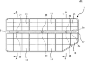
図1〜図3は、本実施形態に係る車両用灯具A1を説明するための図である。図1は、車両用灯具A1の概略正面図である。図2(a)は、図1におけるA−A線断面図である。図2(b)は、図1におけるB−B線断面図である。図3は、車両用灯具A1における制御に関する部分の機能ブロック図である。図1および図2に示す車両用灯具A1は、車両の前方の左側に配置されて、前方に光を照射する前照灯である。なお、車両の前方の右側に配置される前照灯の構造も、車両用灯具A1と同様であり、車両用灯具A1を左右反転させたものになる。 FIGS. 1 to 3 are views for explaining a vehicle lamp A1 according to the present embodiment. FIG. 1 is a schematic front view of a vehicular lamp A1. FIG. 2A is a cross-sectional view taken along the line AA in FIG. FIG. 2B is a cross-sectional view taken along the line B-B in FIG. FIG. 3 is a functional block diagram of a portion related to control in the vehicular lamp A1. The vehicle lamp A1 shown in FIGS. 1 and 2 is a headlight which is disposed on the front left side of the vehicle and emits light to the front. In addition, the structure of the headlight arrange | positioned on the front right side of a vehicle is also the same as that of vehicle lamp A1, and becomes what left-right reversed vehicle lamp A1.
車両用灯具A1は、リフレクタ1、基板2、ロービームLED31〜34、ハイビームLED35,36、駆動回路41〜43、および制御回路5を備えている。なお、実際には、車両用灯具A1は、ハウジングおよびアウターレンズを備えているが、図1および図2においては記載を省略している。ハウジングは、例えば合成樹脂製であり、少なくとも車両前方側に開口が設けられている。アウターレンズは、光を透過する、例えば合成樹脂製であり、ハウジングの開口部分を覆っている。リフレクタ1、基板2、ロービームLED31〜34、ハイビームLED35,36、駆動回路41〜43、および制御回路5は、ハウジングおよびアウターレンズによって形成される灯室に収納されている。ハウジングおよびアウターレンズの形状および材質は、適宜設計される。なお、以下では、ロービームLED31〜34およびハイビームLED35,36をまとめて総称する場合、「LED31〜36」と記載する。
The vehicular lamp A1 includes a
リフレクタ1は、各LED31〜36が発する光を、車両前方に向けて反射させるものであり、図示しない支持部材によってハウジングに固定されている。リフレクタ1は、車両前方側に開口した凹形状をなす。リフレクタ1は、例えば合成樹脂によって一体的に形成されており、少なくとも内側部分の表面にはアルミ蒸着または銀塗装による反射処理が施されている。
The
リフレクタ1は、内側に突出部17を備えている。突出部17は、リフレクタ1の内側を上下方向の中央より上寄りに配置され、リフレクタ1の内側の左右両端まで延びている。突出部17の裏側には、空間17aが設けられている。また、突出部17には、空間17aから上方に開口する3つの孔17bと、下方に開口する3つの孔17cとが形成されている。空間17aには、基板2のLED31〜36が搭載されている端部が挿入されている。孔17bおよび孔17cは、各LED31〜36の位置に合わせて配置されている。
The
リフレクタ1の内側は、突出部17によって上下に分けられ、上側部分と下側部分とは、それぞれ左右方向に3つに分けられている。上側部分の左側には、反射面11が形成されている。下側部分の左側には、反射面12が形成されている。上側部分の中央には、反射面13が形成されている。下側部分の中央には、反射面14が形成されている。上側部分の右側には、反射面15が形成されている。下側部分の右側には、反射面16が形成されている。各反射面11〜16は、それぞれ、LED31〜36を焦点位置とする回転放物面を基準に形成されており、それぞれ複数の面に分割されている。分割された各面の向きによって、配光が制御される。なお、リフレクタ1の形状および材質は限定されない。
The inside of the
基板2は、例えば略四角形の板状であり、各LED31〜36、駆動回路41〜43、および制御回路5を搭載している。基板2は、一部をリフレクタ1の空間17aに挿入された状態で、支持部材によってハウジングに固定されている。基板2は、厚さ方向において互いに反対側を向く上面2aおよび下面2bを備えている。上面2aにはロービームLED31,33およびハイビームLED35が搭載され、下面2bにはロービームLED32,34およびハイビームLED36が搭載されている。また、上面2aには、駆動回路41〜43も搭載されている。なお、駆動回路41〜43は、下面2bに搭載されていてもよい。また、図示していないが、基板2には、制御回路5を実現するための各電子部品、電源回路を構成する各電子部品、各LED31〜36が発する熱を放出するための放熱部材なども搭載されている。
The
ロービームLED31〜34およびハイビームLED35,36は、白色光を発する発光ダイオードである。ロービームLED31,33およびハイビームLED35は、発光面を上に向けて、基板2の上面2aに搭載されている。ロービームLED32,34およびハイビームLED36は、発光面を下に向けて、基板2の下面2bに搭載されている。なお、本実施形態では、各LED31〜36をそれぞれ1つのLEDとしているが、複数のLEDとしてもよい。また、LEDの形状は限定されない。
The
駆動回路41〜43は、電源回路から電力を供給され、制御回路5より入力されるパルス信号に基づいて、各LED31〜36に駆動電流を供給する。駆動回路41はロービームLED31,32に駆動電流を供給し、駆動回路42はロービームLED33,34に駆動電流を供給し、駆動回路43はハイビームLED35,36に駆動電流を供給する。なお、駆動回路42を備えずに、駆動回路41がロービームLED33,34にも同じ駆動電流を供給するようにしてもよい。
The
駆動回路41、ロービームLED31,32、および、リフレクタ1の反射面11,12は、第1のユニットを構成する(図2(a)参照)。駆動回路41から供給される駆動電流に応じて、ロービームLED31,32は発光する。ロービームLED31が発した光は、孔17bを通って、反射面11によって反射され、車両前方に照射される。また、ロービームLED32が発した光は、孔17cを通って、反射面12によって反射され、車両前方に照射される。反射面11,12は、ロービームの配光パターンのうち低領域の広い照射領域に光を拡散させて照射するように設計されている。これにより、第1のユニットは、ロービームの配光パターンのうち低領域の広い照射領域を形成する。
The
駆動回路42、ロービームLED33,34、および、リフレクタ1の反射面13,14は、第2のユニットを構成する。駆動回路42から供給される駆動電流に応じて、ロービームLED33,34は発光する。ロービームLED33が発した光は、孔17bを通って、反射面13によって反射され、車両前方に照射される。また、ロービームLED34が発した光は、孔17cを通って、反射面14によって反射され、車両前方に照射される。反射面13,14は、ロービームの配光パターンのうち、カットオフラインを形成させるための狭い照射領域に光を集中させて照射するように設計されている。これにより、第2のユニットは、ロービームの配光パターンのうち低領域の狭い照射領域を形成する。第1のユニットおよび第2のユニットが、本発明の「第1の前照灯」に相当する。
The
駆動回路43、ハイビームLED35,36、および、リフレクタ1の反射面15,16は、第3のユニットを構成する(図2(b)参照)。駆動回路43から供給される駆動電流に応じて、ハイビームLED35,36は発光する。ハイビームLED35が発した光は、孔17bを通って、反射面15によって反射され、車両前方に照射される。また、ハイビームLED36が発した光は、孔17cを通って、反射面16によって反射され、車両前方に照射される。反射面15,16は、ロービームの低領域の配光パターンより上方に位置する、ハイビームの配光パターンを形成する光を照射するように設計されている。これにより、第3のユニットは、ハイビームの配光パターンを形成する。また、第3のユニットは、ロービームの配光パターンのうち、オーバーヘッドサインを照らすための配光パターンを形成する。第3ユニットが、本発明の「第2の前照灯」に相当する。
The
本実施形態では、リフレクタ1の反射面11,12は、ロービームの配光パターンのうち低領域の広い照射領域にのみ配光を行う。また、リフレクタ1の反射面13,14は、ロービームの配光パターンのうち低領域の狭い照射領域にのみ配光を行う。つまり、ロービーム用のリフレクタである反射面11〜14は、オーバーヘッド用の配光を行わず、ロービームの低領域の配光のみを行う。また、本実施形態では、第3のユニットは、ハイビームの配光パターンを形成し、また、オーバーヘッドサイン用の配光パターンを形成する。したがって、第3のユニットは、法規的には、ハイビーム用の前照灯であり、かつ、ロービーム用の前照灯でもある。
In the present embodiment, the reflection surfaces 11 and 12 of the
制御回路5は、各LED31〜36の発光を制御する回路であり、基板2に搭載されたマイクロコンピュータなどの各電子部品によって実現される。制御回路5は、スイッチ7から入力される操作信号に応じて、各LED31〜36の発光を制御する。スイッチ7は、車内に配置され、運転者によって操作される。スイッチ7は、運転者によって、車両用灯具A1をオフにする場合、車両用灯具A1にロービームを照射させる場合、および、車両用灯具A1にハイビームを照射させる場合とで切り替えられる。スイッチ7は、各場合に対応した操作信号を制御回路5に出力する。制御回路5は、スイッチ7から入力される操作信号に応じて、各LED31〜36の発光状態(点灯または消灯)を切り替える。また、制御回路5は、いわゆるPWM調光によって、ハイビームLED35,36が発する光の明るさを切り替える。
The control circuit 5 is a circuit that controls the light emission of each of the
PWM調光は、LEDに電流を流して点灯させる点灯期間と、電流を遮断して消灯させる消灯期間とを、一定の短い周期で交互に切り替え、1周期における点灯期間の占める割合(デューティ比)を変化させることで、LEDの明るさを変化させる。切り替えの周期を短くする(周波数を高くする)ことで、人の目には点灯と消灯によるちらつきが認識できなくなる。デューティ比が高くなると、点灯期間が長くなるので、LEDが発する光は明るくなり、デューティ比が低くなると、点灯期間が短くなるので、LEDが発する光は暗くなる。 In PWM dimming, a lighting period in which a current is supplied to an LED to light up and a switching-off period in which a current is shut off and switching off are alternately switched in a fixed short cycle, and the ratio of the lighting period in one cycle (duty ratio) Changes the brightness of the LED. By shortening the switching cycle (increasing the frequency), the human eye can not recognize flicker due to lighting and extinguishing. When the duty ratio becomes high, the lighting period becomes long, so that the light emitted from the LED becomes bright. When the duty ratio becomes low, the lighting period becomes short, so the light emitted from the LED becomes dark.
制御回路5は、スイッチ7から車両用灯具A1をオフにする操作信号が入力されている間、各LED31〜36を消灯させる。また、スイッチ7から車両用灯具A1にハイビームを照射させる操作信号が入力されている間、各LED31〜36を最大の明るさで点灯させる。また、スイッチ7から車両用灯具A1にロービームを照射させる操作信号が入力されている間、ロービームLED31〜34を最大の明るさで点灯させ、かつ、ハイビームLED35,36を明るさを低下させた状態で点灯させる。この場合、ハイビームLED35,36が発する光は、オーバーヘッドサインを照らすための配光パターンを形成する。
The control circuit 5 turns off the
制御回路5は、ハイビームLED35,36を最大の明るさで点灯させる場合、点灯期間のデューティ比を所定の第1の値(例えば100%)とするように制御する。また、明るさを低下させた状態で点灯させる場合、点灯期間のデューティ比を所定の第2の値(例えば1%)とするように制御する。本実施形態では、第2の値を第1の値の0.5〜1%としている。これは、デューティ比を第1の値としたときに第3ユニットが発する光の光度(最大光度)が約60000カンデラなので、オーバーヘッドサインを照らすための光として法規で定められている光度の範囲(最大625カンデラ)に合わせるためである。なお、第1の値および第2の値は限定されず、ハイビームLED35,36の規格や照射したい光の光度によって適宜設計される。
When lighting the
図3に示すように、制御回路5は、機能ブロックとして、切替部51、パルス生成部52,53、およびデューティ設定部54を備えている。
As shown in FIG. 3, the control circuit 5 includes a
切替部51は、スイッチ7から入力される操作信号に応じて、パルス生成部52,53、およびデューティ設定部54に指令を出す。具体的には、切替部51は、スイッチ7から車両用灯具A1をオフにする操作信号が入力されている間、パルス生成部52,53にパルス信号を生成しないように指令する。また、スイッチ7から車両用灯具A1にハイビームを照射させる操作信号が入力されている間、デューティ設定部54にデューティ比を第1の値とするように指令し、パルス生成部52,53にパルス信号を生成するように指令する。また、スイッチ7から車両用灯具A1にロービームを照射させる操作信号が入力されている間、デューティ設定部54にデューティ比を第2の値とするように指令し、パルス生成部52,53にパルス信号を生成するように指令する。
The switching
パルス生成部52は、切替部51からの指令に応じて、デューティ比を第1の値とするパルス信号を生成し、駆動回路41,42に出力する。デューティ比を第1の値とするパルス信号を入力された駆動回路41(42)は、当該パルス信号に応じた駆動電流を、ロービームLED31,32(LED33,34)に供給する。これにより、ロービームLED31〜34の点灯期間のデューティ比が第1の値となり、ロービームLED31〜34は、最大の明るさで点灯する。一方、パルス生成部52がパルス信号を生成しない場合、駆動回路41(42)は、駆動電流をロービームLED31,32(LED33,34)に供給しない。したがって、ロービームLED31〜34は消灯する。
The
デューティ設定部54は、切替部51からの指令に応じて、パルス生成部53にデューティ比を設定する。
The
パルス生成部53は、切替部51からの指令に応じてパルス信号を生成し、駆動回路43に出力する。その際、パルス生成部53は、デューティ設定部54によって設定されたデューティ比でパルス信号を生成する。デューティ比を第1の値とするパルス信号を入力された駆動回路43は、当該パルス信号に応じた駆動電流を、ハイビームLED35,36に供給する。これにより、ハイビームLED35,36の点灯期間のデューティ比が第1の値となり、ハイビームLED35,36は、最大の明るさで点灯する。また、デューティ比を第2の値とするパルス信号を入力された駆動回路43は、当該パルス信号に応じた駆動電流を、ハイビームLED35,36に供給する。これにより、ハイビームLED35,36の点灯期間のデューティ比が第2の値となり、ハイビームLED35,36は、明るさを低下させた状態で点灯する。一方、パルス生成部53がパルス信号を生成しない場合、駆動回路43は、駆動電流をハイビームLED35,36に供給しない。したがって、ハイビームLED35,36は消灯する。
The
次に、本実施形態に係る車両用灯具A1の作用および効果について説明する。 Next, the operation and effects of the vehicular lamp A1 according to the present embodiment will be described.
本実施形態によると、制御回路5は、スイッチ7から入力される操作信号に応じて、各LED31〜36の発光を制御する。制御回路5は、スイッチ7からハイビームを照射させる操作信号が入力されている間、各LED31〜36を最大の明るさで点灯させる。したがって、第1〜第3のユニットがいずれも最大の明るさの光を照射する。これにより、第1のユニットおよび第2のユニットがロービームの低領域の配光パターンを形成し、第3のユニットがハイビームの配光パターンを形成する。また、制御回路5は、スイッチ7からロービームを照射させる操作信号が入力されている間、ロービームLED31〜34を最大の明るさで点灯させ、ハイビームLED35,36を明るさを低下させた状態で点灯させる。したがって、第1のユニットおよび第2のユニットは最大の明るさの光を照射し、第3のユニットは明るさを低下させた光を照射する。これにより、第1のユニットおよび第2のユニットがロービームの低領域の配光パターンを形成し、第3のユニットがオーバーヘッドサインを照らすための配光パターンを形成する。
According to the present embodiment, the control circuit 5 controls the light emission of each of the
つまり、車両用灯具A1は、ロービーム照射時に、第3のユニットから明るさを低下させた光を照射させて、この光をオーバーヘッドサイン用の配光に利用する。当該オーバーヘッドサイン用の配光は、明るさを低下させた光なので、対向車の運転手に眩しさを感じさせることを抑制できる。また、当該オーバーヘッドサイン用の配光は、第3のユニットから照射されるので、ロービームの低領域の配光パターンを形成するための第1のユニットおよび第2のユニットの光を減少させない。 That is, at the time of low beam irradiation, the vehicle lamp A1 irradiates the light whose brightness is reduced from the third unit, and uses this light for light distribution for the overhead sign. Since the light distribution for the overhead sign is light whose brightness is lowered, it is possible to suppress the driver of the oncoming vehicle from feeling glare. Further, since the light distribution for the overhead sign is irradiated from the third unit, the light of the first unit and the second unit for forming the low-beam light distribution pattern of the low beam is not reduced.
従来の、リフレクタの一部の反射面で反射させた光をオーバーヘッドサイン用の配光に利用する方式の場合、ロービーム照射時にはハイビーム照射用の前照灯は消灯している。この場合、車両前方から見たときに、車両用灯具のアウターレンズの一部が暗くなる。一方、車両用灯具A1の場合、第3のユニット(ハイビーム照射用の前照灯)は、ロービーム照射時にも、明るさを低下させているが光を照射する。したがって、車両前方から見たときに、車両用灯具A1のアウターレンズ全体が光って見えるので、外観の意匠性を向上させることができる。 In the case of the conventional system in which light reflected by a part of the reflecting surface of the reflector is used for light distribution for overhead sign, the headlight for high beam irradiation is turned off at the time of low beam irradiation. In this case, when viewed from the front of the vehicle, part of the outer lens of the vehicle lamp becomes dark. On the other hand, in the case of the vehicle lamp A1, the third unit (headlight for high beam irradiation) emits light, although the brightness is lowered even at the time of low beam irradiation. Therefore, when viewed from the front of the vehicle, the entire outer lens of the vehicle lamp A1 looks bright, so that the design of the appearance can be improved.
なお、本実施形態では、ハイビームを照射するときに、ロービームも合わせて照射する場合について説明したが、これに限られない。ハイビームを照射するときは、ロービームは照射しないようにしてもよい。具体的には、制御回路5は、スイッチ7からハイビームを照射させる操作信号が入力されている間、各LED31〜34を消灯させてもよい。
In the present embodiment, when the high beam is irradiated, the case where the low beam is also irradiated is described, but the present invention is not limited to this. When the high beam is irradiated, the low beam may not be irradiated. Specifically, the control circuit 5 may turn off the
本実施形態では、制御回路5が、PWM調光によって、ハイビームLED35,36が発する光の明るさを切り替える場合について説明したが、これに限られない。制御回路5は、ハイビームLED35,36に流す電流の大きさを、駆動回路43に変更させることで、ハイビームLED35,36が発する光の明るさを切り替えるようにしてもよい。
In the present embodiment, the control circuit 5 switches the brightness of the light emitted from the
本実施形態では、光源としてLEDが用いられているが、これに限られない。光源は、例えばハロゲンバルブなどであってもよい。ただし、少なくともハイビーム用の光源は明るさが切り替え可能でなければならないので、他の光源を用いる場合、明るさを制御できるようにする必要がある。したがって、ハイビーム用の光源は、容易に明るさを制御できるLEDを用いるのが望ましい。一方、ロービーム用の光源は、明るさを切り替える必要がないので、LED以外の光源を用いてもよい。 In the present embodiment, an LED is used as a light source, but the present invention is not limited to this. The light source may be, for example, a halogen bulb. However, since at least the light source for high beam must be switchable in brightness, it is necessary to be able to control the brightness when using another light source. Therefore, as a light source for high beam, it is desirable to use an LED whose brightness can be easily controlled. On the other hand, since the light source for low beam does not need to switch the brightness, a light source other than the LED may be used.
本実施形態では、スイッチ7によって、車両用灯具A1の照射状態を切り替える場合について説明したが、これに限られない。外の明るさによって、車両用灯具A1の点灯と消灯とを自動的に切り替えるようにしてもよい。また、前方を撮影した画像などに基づいて対向車や前を走る車を識別して、自動的にハイビームとロービームとを切り替えるようにしてもよい。 Although the case where the irradiation state of the vehicle lamp A1 is switched by the switch 7 has been described in the present embodiment, the present invention is not limited thereto. The lighting and extinguishing of the vehicular lamp A1 may be automatically switched depending on the outside brightness. In addition, it is possible to automatically switch between the high beam and the low beam by identifying an oncoming vehicle or a vehicle traveling in the front based on an image obtained by photographing the front.
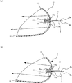
なお、リフレクタ1の形状、反射面の数および配置は限定されない。例えば、LED31,33,35をロービームLEDとし、LED32,34,36をハイビームLEDとして、リフレクタ1の上側の反射面11,13,15がロービームを照射し、下側の反射面12,14,16がハイビームを照射するようにしてもよい。また、図4(a)に示す車両用灯具A2のように、リフレクタ1が反射面12,14,16だけを備え(反射面11,13,15を備えず)、ロービームLED32,34およびハイビームLED36だけを備える(ロービームLED31,33およびハイビームLED35を備えず)ようにしてもよい。また、図4(b)に示す車両用灯具A3のように、リフレクタ1が反射面11,12,15,16だけを備え(反射面13,14を備えず)、ロービームLED31,32およびハイビームLED35,36だけを備える(ロービームLED33,34を備えず)ようにしてもよい。この場合、反射面11,12が、ロービームの低領域の配光パターンのうち、広い照射領域および狭い領域の両方に、光を照射できるように設計される。また、リフレクタ1を一体とせず、各反射面毎のリフレクタを設けるようにしてもよい。
In addition, the shape of the
本発明に係る車両用灯具は、上述した実施形態に限定されるものではない。本発明に係る車両用灯具の各部の具体的な構成は、種々に設計変更自在である。 The vehicular lamp according to the present invention is not limited to the embodiment described above. The specific configuration of each part of the vehicle lamp according to the present invention can be varied in design in many ways.
A1,A2,A3:車両用灯具
1 :リフレクタ
11〜14:反射面
15,16:反射面
17 :突出部
17a :空間
17b,17c:孔
2 :基板
2a :上面
2b :下面
31〜34:ロービームLED
35,36:ハイビームLED
41〜43:駆動回路
5 :制御回路
51 :切替部
52〜53:パルス生成部
54 :デューティ設定部
7 :スイッチ
A1, A2 and A3: Vehicle lamps 1:
35, 36: High beam LED
41 to 43: drive circuit 5: control circuit 51: switching
Claims (1)
前記第1の前照灯より上方に光を照射する第2の前照灯と、
ハイビーム用の配光を行う状態とロービーム用の配光を行う状態とを切り替える制御回路と、
を備えており、
前記制御回路は、ロービーム用の配光を行う状態とする場合に、前記第1の前照灯に光の照射を行わせ、かつ、前記第2の前照灯に明るさを低下させた光の照射を行わせる、
ことを特徴とする車両用灯具。 With the first headlight,
A second headlight that emits light above the first headlight;
A control circuit that switches between a state in which light distribution for high beam is performed and a state in which light distribution for low beam is performed;
Equipped with
The control circuit causes the first headlight to emit light and lowers the brightness of the second headlight when the low beam light distribution is to be performed. Make the irradiation of
A vehicle lamp characterized in that.
Priority Applications (1)
| Application Number | Priority Date | Filing Date | Title |
|---|---|---|---|
| JP2017250930A JP7159515B2 (en) | 2017-12-27 | 2017-12-27 | vehicle lamp |
Applications Claiming Priority (1)
| Application Number | Priority Date | Filing Date | Title |
|---|---|---|---|
| JP2017250930A JP7159515B2 (en) | 2017-12-27 | 2017-12-27 | vehicle lamp |
Publications (2)
| Publication Number | Publication Date |
|---|---|
| JP2019117724A true JP2019117724A (en) | 2019-07-18 |
| JP7159515B2 JP7159515B2 (en) | 2022-10-25 |
Family
ID=67304526
Family Applications (1)
| Application Number | Title | Priority Date | Filing Date |
|---|---|---|---|
| JP2017250930A Active JP7159515B2 (en) | 2017-12-27 | 2017-12-27 | vehicle lamp |
Country Status (1)
| Country | Link |
|---|---|
| JP (1) | JP7159515B2 (en) |
Cited By (1)
| Publication number | Priority date | Publication date | Assignee | Title |
|---|---|---|---|---|
| JP7406357B2 (en) | 2019-11-27 | 2023-12-27 | 株式会社小糸製作所 | Vehicle lights |
Citations (4)
| Publication number | Priority date | Publication date | Assignee | Title |
|---|---|---|---|---|
| JP2009179113A (en) * | 2008-01-29 | 2009-08-13 | Koito Mfg Co Ltd | Head lamp device for vehicle and its control method |
| JP2009214812A (en) * | 2008-03-12 | 2009-09-24 | Koito Mfg Co Ltd | Vehicular headlight device and its control method |
| JP2010163141A (en) * | 2009-01-19 | 2010-07-29 | Koito Mfg Co Ltd | Vehicle headlight device |
| JP2013082390A (en) * | 2011-10-12 | 2013-05-09 | Koito Mfg Co Ltd | Vehicle headlamp control system |
-
2017
- 2017-12-27 JP JP2017250930A patent/JP7159515B2/en active Active
Patent Citations (4)
| Publication number | Priority date | Publication date | Assignee | Title |
|---|---|---|---|---|
| JP2009179113A (en) * | 2008-01-29 | 2009-08-13 | Koito Mfg Co Ltd | Head lamp device for vehicle and its control method |
| JP2009214812A (en) * | 2008-03-12 | 2009-09-24 | Koito Mfg Co Ltd | Vehicular headlight device and its control method |
| JP2010163141A (en) * | 2009-01-19 | 2010-07-29 | Koito Mfg Co Ltd | Vehicle headlight device |
| JP2013082390A (en) * | 2011-10-12 | 2013-05-09 | Koito Mfg Co Ltd | Vehicle headlamp control system |
Cited By (1)
| Publication number | Priority date | Publication date | Assignee | Title |
|---|---|---|---|---|
| JP7406357B2 (en) | 2019-11-27 | 2023-12-27 | 株式会社小糸製作所 | Vehicle lights |
Also Published As
| Publication number | Publication date |
|---|---|
| JP7159515B2 (en) | 2022-10-25 |
Similar Documents
| Publication | Publication Date | Title |
|---|---|---|
| JP5607634B2 (en) | Lighting unit and vehicle headlamp | |
| US8070338B2 (en) | Three-mode integrated headlamp | |
| US8172442B2 (en) | Vehicle lamp | |
| JP2005141917A (en) | Vehicular headlight | |
| US9623792B2 (en) | Vehicle headlight | |
| JP6889588B2 (en) | Vehicle lighting | |
| JP2006216251A (en) | Vehicle head lamp device | |
| JP2010067417A (en) | Headlight device for vehicle | |
| US10393337B2 (en) | Vehicular headlamp | |
| CN109237414B (en) | Optical unit | |
| CN110939913A (en) | Vehicle lamp and control method thereof | |
| JP2023086990A (en) | Vehicular lighting fixture | |
| JP7159515B2 (en) | vehicle lamp | |
| EP2186679A1 (en) | Vehicle lighting fixture | |
| CN109630974B (en) | Vehicle headlamp | |
| JP5316238B2 (en) | Vehicle lighting | |
| KR101614849B1 (en) | Structure of high and low beams head light | |
| CN113795705A (en) | Vehicle lamp | |
| CN111556945A (en) | Vehicle headlamp | |
| WO2020246334A1 (en) | Lamp for two-wheeled vehicle | |
| CN209926250U (en) | Head lamp for vehicle | |
| CN216480754U (en) | Dipped beam auxiliary unit of automobile headlamp | |
| JP5323521B2 (en) | Vehicle headlamp device | |
| KR20170110384A (en) | Head lamp for vehicle | |
| JP2013054831A (en) | Vehicle lamp |
Legal Events
| Date | Code | Title | Description |
|---|---|---|---|
| A621 | Written request for application examination |
Free format text: JAPANESE INTERMEDIATE CODE: A621 Effective date: 20201106 |
|
| A977 | Report on retrieval |
Free format text: JAPANESE INTERMEDIATE CODE: A971007 Effective date: 20210927 |
|
| A131 | Notification of reasons for refusal |
Free format text: JAPANESE INTERMEDIATE CODE: A131 Effective date: 20211019 |
|
| A521 | Request for written amendment filed |
Free format text: JAPANESE INTERMEDIATE CODE: A523 Effective date: 20211203 |
|
| A131 | Notification of reasons for refusal |
Free format text: JAPANESE INTERMEDIATE CODE: A131 Effective date: 20220412 |
|
| A521 | Request for written amendment filed |
Free format text: JAPANESE INTERMEDIATE CODE: A523 Effective date: 20220425 |
|
| TRDD | Decision of grant or rejection written | ||
| A01 | Written decision to grant a patent or to grant a registration (utility model) |
Free format text: JAPANESE INTERMEDIATE CODE: A01 Effective date: 20220913 |
|
| A61 | First payment of annual fees (during grant procedure) |
Free format text: JAPANESE INTERMEDIATE CODE: A61 Effective date: 20220913 |
|
| R150 | Certificate of patent or registration of utility model |
Ref document number: 7159515 Country of ref document: JP Free format text: JAPANESE INTERMEDIATE CODE: R150 |