EP0106224B1 - Massagegerät - Google Patents
Massagegerät Download PDFInfo
- Publication number
- EP0106224B1 EP0106224B1 EP83109662A EP83109662A EP0106224B1 EP 0106224 B1 EP0106224 B1 EP 0106224B1 EP 83109662 A EP83109662 A EP 83109662A EP 83109662 A EP83109662 A EP 83109662A EP 0106224 B1 EP0106224 B1 EP 0106224B1
- Authority
- EP
- European Patent Office
- Prior art keywords
- massage
- massage apparatus
- base
- vessel
- cushion
- Prior art date
- Legal status (The legal status is an assumption and is not a legal conclusion. Google has not performed a legal analysis and makes no representation as to the accuracy of the status listed.)
- Expired
Links
- XLYOFNOQVPJJNP-UHFFFAOYSA-N water Substances O XLYOFNOQVPJJNP-UHFFFAOYSA-N 0.000 claims abstract description 14
- 238000010438 heat treatment Methods 0.000 claims description 10
- 239000013013 elastic material Substances 0.000 claims description 3
- 229920001821 foam rubber Polymers 0.000 claims description 3
- 230000000638 stimulation Effects 0.000 claims description 2
- 210000002683 foot Anatomy 0.000 description 6
- 210000003414 extremity Anatomy 0.000 description 3
- 238000010276 construction Methods 0.000 description 2
- 230000002349 favourable effect Effects 0.000 description 1
- 238000001746 injection moulding Methods 0.000 description 1
- 238000004519 manufacturing process Methods 0.000 description 1
- 239000004033 plastic Substances 0.000 description 1
- 230000004936 stimulating effect Effects 0.000 description 1
- 230000001225 therapeutic effect Effects 0.000 description 1
- 210000003371 toe Anatomy 0.000 description 1
Images

Classifications
-
- A—HUMAN NECESSITIES
- A61—MEDICAL OR VETERINARY SCIENCE; HYGIENE
- A61H—PHYSICAL THERAPY APPARATUS, e.g. DEVICES FOR LOCATING OR STIMULATING REFLEX POINTS IN THE BODY; ARTIFICIAL RESPIRATION; MASSAGE; BATHING DEVICES FOR SPECIAL THERAPEUTIC OR HYGIENIC PURPOSES OR SPECIFIC PARTS OF THE BODY
- A61H23/00—Percussion or vibration massage, e.g. using supersonic vibration; Suction-vibration massage; Massage with moving diaphragms
- A61H23/02—Percussion or vibration massage, e.g. using supersonic vibration; Suction-vibration massage; Massage with moving diaphragms with electric or magnetic drive
-
- A—HUMAN NECESSITIES
- A61—MEDICAL OR VETERINARY SCIENCE; HYGIENE
- A61H—PHYSICAL THERAPY APPARATUS, e.g. DEVICES FOR LOCATING OR STIMULATING REFLEX POINTS IN THE BODY; ARTIFICIAL RESPIRATION; MASSAGE; BATHING DEVICES FOR SPECIAL THERAPEUTIC OR HYGIENIC PURPOSES OR SPECIFIC PARTS OF THE BODY
- A61H35/00—Baths for specific parts of the body
- A61H35/006—Baths for specific parts of the body for the feet
-
- A—HUMAN NECESSITIES
- A61—MEDICAL OR VETERINARY SCIENCE; HYGIENE
- A61H—PHYSICAL THERAPY APPARATUS, e.g. DEVICES FOR LOCATING OR STIMULATING REFLEX POINTS IN THE BODY; ARTIFICIAL RESPIRATION; MASSAGE; BATHING DEVICES FOR SPECIAL THERAPEUTIC OR HYGIENIC PURPOSES OR SPECIFIC PARTS OF THE BODY
- A61H2205/00—Devices for specific parts of the body
- A61H2205/12—Feet
Definitions
- the invention relates to a massage device, in particular for foot care, with at least one support, preferably provided with knobs, serving as a massage surface, which can be set in vibration with a vibration device and forms the bottom of a water-fillable vessel which is formed in one piece with the vibration device.
- Massage devices of this type offer the possibility of massaging tired or overexerted limbs without the use of a massage therapist and thus stimulating the user's circulation. So far, however, they have mostly been relatively complex to set up and often uncomfortable to use.
- a massager with a smooth, i.e. Knoppen-free edition which can be set in vibration with a vibration device having a motor.
- This support forms the relatively deep bottom of a water-filled vessel, which is formed in one piece with the vibration device.
- the massage device known from US-A-4 019 502 is relatively complex in its construction and, moreover, also limited in its applicability, especially since it only allows massages with a non-nubbed massage surface.
- the invention has for its object to provide a massage device that is simple in construction, easy to handle and can also be used universally.
- a massage device in which the back of the vessel bottom is also designed as a massage surface, so that the massage device can also be used in the turned position.
- a massage device designed in this way can be used with or without a water bath and, because it has two massage surfaces, can also be used for massages of different quality after it has been easily turned over by 180 °.
- An additional advantage of the massage device according to the invention is that it has a massage area with the second massage area formed by the back of the vessel bottom, which allows the massage device to rest on body parts and limbs of the user, which is the case with the relatively low-lying massage area of the device US-A-4 019 502 is not the case.
- the vessel base serving as a support can run at an angle, i.e.
- it should preferably be arranged diagonally upward away from the user, which results in several advantages, in particular for the foot massage, which is generally carried out while seated.
- a floor that slopes away from the user increases comfort and, on the other hand, it results in considerable water savings when working with a water bath. The latter is particularly useful because of the energy savings associated with it, when working with a tempered water bath.
- an electrical surface heating element is provided for the base serving as the massage surface, which considerably increases the possible use and effectiveness of the device, since the built-in heating element heats not only the base, but also, if desired, the water in the vessel can be.
- the possible uses of the massage device according to the invention can also be increased by a cushion which can be placed on one and / or the other side of the floor and whose inclination compensates, and which is preferably designed with a nub on at least one side.
- the knobs with the base designed as a massage surface and / or that of the aforementioned cushion can have different heights and can also be designed differently, which also increases the possible uses of the massage device according to the invention.
- the base designed as a massage surface is essentially plate-shaped and the vibration device and preferably also its drive are arranged within this base which can be used on both sides.
- Two separate, preferably staggered vibration devices can be provided for the floor designed as a massage surface, the vibration strength, frequency and / or phase of which can preferably be set separately, with the advantage that the massage can be carried out at intervals and / or with different intensities if desired, for example, by superimposing the vibrations with a slightly different frequency.
- a timer can be provided for the vibrators and / or the heating of the bottom, the actuator of which is preferably provided on the outer wall of the vessel.
- the massage device according to the invention can also be provided with an electrical stimulation device in order to increase its possible uses and its therapeutic effectiveness.
- molded, preferably laterally arranged, bow-like handles are provided, which are designed as support members for the vessel which cause the inclined position of the base.
- an intermediate plate that can be placed on the floor can be provided, which on its support side has depressions corresponding to the knobs of the floor, on the other hand it is preferably flat on the side facing away from the floor.
- Such an intermediate plate has the advantage that the Device users can also perform a foot massage without damaging or soiling the device without taking off their shoes.
- the aforementioned intermediate plate can have a protruding, all-round edge on the side facing away from the floor.
- attachable straps can be provided, by means of which it can be attached to body parts or limbs of the user or other objects, if necessary with the interposition of the wedge-shaped cushion.
- the cushion itself can also be equipped with a vibration device and / or a heater.
- Belts can also be provided on the pillow.
- the aforementioned cushion which can be placed on one and / or the other side of the floor, can consist of elastic material, preferably of foam rubber.
- a remote control can be provided for the vibration device and / or the heating element for more convenient actuation.
- a preferred embodiment of the massage device according to the invention works with battery power, which is supplied by batteries arranged in the device itself.
- the power can also be supplied from outside the device if desired, especially when heated.
- the massage device shown is essentially rectangular in plan view (cf. FIG. 1). Its two long side parts 1, 2, one of which can be seen in FIG. 2 and the other in FIG. 3, each have essentially the shape of a right-angled triangle, the short side of which merges into the front side part 3 of the device. Two switch buttons 4, 5 are arranged on the front part 3 of the device.
- the obliquely to the horizontal sides of the longitudinal side parts 1, 2 merge into a substantially plate-shaped bottom 6, which is attached in the view of FIG. 2 below on the front side part 3 of the device and above on a web 7 connecting the two longitudinal side parts 1, 2 , with which the front side part 3 of the device is connected via two angular brackets 8, 9 which, if desired, can be designed to be removable.
- the bottom 6 is hollow and contains on the one hand an electrical surface heating element which can be controlled via the switch button 4 and on the other hand a centrally arranged vibration device which can be controlled via the switch button 5. Both sides of the bottom 6 are designed as massage surfaces and have knobs 10, only a few of which are shown in the drawing.
- the edge regions of the base 6 are each corrugated, as shown schematically, so that the base 6 can easily take over the vibrations generated by the centrally arranged vibration device.
- a substantially wedge-shaped cushion 11 can be placed on the floor 6, which is shown in broken lines in FIG. 2.
- the height of the cushion 11 is preferably such that the brackets 8, 9 do not touch the floor when the device is placed on the floor according to the view in FIG. 2.
- the two long side parts 1, 2, the front side part 3 and the bottom 6 define a water-fillable vessel, the bottom of which extends obliquely upwards away from the front side part 3 and thus for one in front of the Front side part 3 seated person forms a comfortable footrest, on which the heels can be arranged lower than the toes, which accommodates a comfortable sitting position. If the user's feet have taken up this position, the surface heating element arranged in the bottom 6 and / or the vibrating device likewise arranged in the bottom 6 can be actuated by actuating the front control buttons 4, 5 and the foot massage in the water bath can thus be started.
- the massage device shown offers two options for this, which result from the fact that the bottom 6 can be used on both sides as a massage surface and the device can also be used in a turned position.
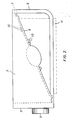
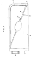
- the two positions in which the massage device can work are each shown schematically in FIGS. 2 and 3.
- the position according to FIG. 2 it is possible to work both with and without a water bath. 3 only without a water bath.
- the bottom 6 runs obliquely from the bottom upward as seen by the user.
- the switch buttons point to the user, while in the position according to FIG. 3 they are on the side of the device facing away from the user.
- the brackets 8, 9 ensure that the bottom of the massage device also assumes the inclined position which is favorable for the user in the position according to FIG. 2 and can also be used as handles. It is also possible to use these Brackets 8, 9 to attach a tether by means of which the device can be attached, for example, to the back of a patient, so that the vibrations generated by the vibrating device can be transmitted from the floor 6 via the cushion 11 to the patient's back without the patient It would be necessary to keep the device in the desired position at all times.
- the current required for the operation of the vibration device and the heating element can be supplied by batteries arranged in the front side part 3 or by a power supply unit for which a connection socket (not shown) is provided on the front side part 3.
- the two longitudinal side parts 1, 2, the front side part 3, the bottom 6 and the two brackets 8, 9 can be made in one piece from plastic, the production preferably being carried out by injection molding. Since only one side of the base 6, namely the side of the base 5 pointing upwards in FIG. 2, comes into contact with water, it is possible to provide a closure cover on the other side of the base 6, through which the interior of the base 6 is accessible is.
- the massage device according to the invention forms a compact, easily transportable and universally usable massage device with which it is possible to work both with and without a water bath.
Landscapes
- Health & Medical Sciences (AREA)
- Epidemiology (AREA)
- Pain & Pain Management (AREA)
- Physical Education & Sports Medicine (AREA)
- Rehabilitation Therapy (AREA)
- Life Sciences & Earth Sciences (AREA)
- Animal Behavior & Ethology (AREA)
- General Health & Medical Sciences (AREA)
- Public Health (AREA)
- Veterinary Medicine (AREA)
- Percussion Or Vibration Massage (AREA)
- Massaging Devices (AREA)
Description
- Die Erfindung betrifft ein Massagegerät, insbesondere zur Fußpflege, mit wenigstens einer vorzugsweise mit Noppen versehenen, als Massagefläche dienenden Auflage, die mit einer Vibrationseinrichtung in Vibration versetzbar ist und den Boden eines mit Wasser füllbaren Gefäßes bildet, das mit der Vibrationseinrichtung einstückig ausgebildet ist.
- Derartige Massagegeräte bieten die Möglichkeit, ermüdete bzw. überanstrengte Gliedmaßen ohne Inanspruchnahme eines Masseurs zu massieren und damit den Kreislauf des Benutzers zu beleben. Sie waren bisher jedoch zumeist relativ aufwendig in ihrem Aufbau und oft auch unbequem in ihrer Handhabung.
- Aus der US-A-4 019 502 ist ein Massagegerät mit einer glatten, d.h. noppenfreien Auflage bekannt, die mit einer einen Motor aufweisenden Vibrationseinrichtung in Vibration versetzbar ist. Diese Auflage bildet den relativ tiefliegenden Boden eines mit Wasser füllbaren Gefäßes, das mit der Vibrationseinrichtung einstückig ausgebildet ist. Das aus der US-A-4 019 502 bekannte Massagegerät ist relativ aufwendig in seinem Aufbau und darüber hinaus auch beschränkt in seiner Anwendbarkeit, zumal es nur Massagen mit einer ungenoppten Massagefläche gestattet.
- Der Erfindung liegt die Aufgabe zugrunde, ein Massagegerät zu schaffen, das einfach in seinem Aufbau ist, sich leicht handhaben läßt und darüber hinaus universell einsetzbar ist.
- Diese Aufgabe wird erfindungsgemäß durch ein Massagegerät gelöst, bei dem die Rückseite des Gefäßbodens ebenfalls als Massagefläche ausgebildet ist, so daß das Massagegerät auch in gewendeter Lage benutzbar ist. Ein so ausgebildetes Massagegerät kann mit oder ohne Wasserbad und zudem, da es über zwei Massageflächen verfügt, nach problemlosem Wenden um 180° auch für Massagen unterschiedlicher Qualität benutzt werden. Als zusätzlicher Vorteil des erfindungsgemäßen Massagegerätes ist zu werten, daß es mit der von der Rückseite des Gefäßbodens gebildeten zweiten Massagefläche über eine Massagefläche verfügt, die eine Auflage des Massagegerätes an Körperstellen und Gliedmaßen des Benutzers gestattet, was bei der relativ tiefliegenden Massagefläche des Gerätes nach der US-A-4 019 502 nicht der Fall ist.
- Der als Auflage dienende Gefäßboden kann schräg verlaufen, d.h. bei Benutzung als Fußmassagegerät vorzugsweise vom Benutzer weg schräg nach oben verlaufend angeordnet sein, wodurch sich mehrere Vorteile ergeben, insbesondere für die Fußmassage, die in aller Regel sitzend vorgenommen wird. Zum einen erhöht ein vom Benutzer weg schräg nach oben verlaufend angeordneter Boden die Bequemlichkeit und zum anderen ergibt er eine nicht unerhebliche Wasserersparnis, wenn mit Wasserbad gearbeitet werden soll. Letzteres ist wegen der damit verbundenen Energieeinsparung besonders dann von Verteil, wenn mit einem temperierten Wasserbad gearbeitet werden soll.
- Bei einer bevorzugten Ausführungsform des erfindungsgemäßen Massagegerätes ist für den als Massagefläche dienenden Boden ein elektrisches Flächenheizelement vorgesehen, wodurch die Einsatzmöglichkeit und die Wirksamkeit des Gerätes beträchtlich erhöht werden, da mit dem eingebauten Heizelement nicht nur der Boden, sondern gewünschtenfalls auch das im Gefäß befindliche Wasser erwärmt werden kann.
- Die Einsatzmöglichkeiten des erfindungsgemäßen Massagegerätes können auch durch ein auf die eine und/oder die andere Seite des Bodens aufsetzbares, dessen Neigung ausgleichendes Kissen erhöht werden, das vorzugsweise mindestens auf einer Seite genoppt ausgebildet ist. Die Noppen mit dem als Massagefläche ausgebildeten Boden und/oder die des vorgenannten Kissens können unterschiedliche Höhe aufweisen und auch sonst unterschiedlich ausgebildet sein, wodurch die Einsatzmöglichkeiten des erfindungsgemäßen Massagegerätes ebenfalls erhöht werden.
- Bei einer bevorzugten Ausführungsform des erfindungsgemäßen Massagegerätes ist der als Massagefläche ausgebildete Boden im wesentlichen plattenförmig ausgebildet und die Vibrationseinrichtung und vorzugsweise auch deren Antrieb sind innerhalb dieses beidseitig benutzbaren Bodens angeordnet.
- Für den als Massagefläche ausgebildeten Boden können zwei getrennte, vorzugsweise versetzt arbeitende Vibrationseinrichtungen vorgesehen sein, deren Schwingungsstärke, Frequenz und/oder Phase vorzugsweise getrennt einstellbar sind, mit dem Vorteil, daß die Massage gewünschtenfalls in Intervallen und/oder mit unterschiedlicher Intensität durchgeführt werden kann, beispielsweise durch Überlagerung der Schwingungen mit geringfügig verschiedener Frequenz.
- Für die Vibratoren und/oder die Heizung des Bodens kann eine Schaltuhr vorgesehen sein, deren Betätigungsglied vorzugsweise an der Gefäßaußenwand vorgesehen ist.
- Das erfindungsgemäße Massagegerät kann zur Erhöhung seiner Einsatzmöglichkeiten und seiner therapeutischen Wirksamkeit auch mit einer Reizstromeinrichtung versehen sein.
- Bei einer bevorzugten Ausführungsform sind angeformte, vorzugsweise seitlich angeordnete, bügelartige Tragegriffe vorgesehen, die als die Schräglage des Bodens bewirkende Stützglieder für das Gefäß ausgebildet sind.
- Beim erfindungsgemäßen Massagegerät kann eine auf den Boden auflegbare Zwischenplatte vorgesehen sein, die auf ihrer Auflageseite den Noppen des Bodens entsprechende Vertiefungen aufweist, auf der dem Boden abgewandten Seite dagegen vorzugsweise eben ausgebildet ist. Eine solche Zwischenplatte bietet den Vorteil, daß der Gerätebenutzer ohne Beschädigung oder Verschmutzung des Gerätes auch eine Fußmassage durchführen kann, ohne hierzu seine Schuhe auszuziehen. Um ein Abrutschen der Schuhe während der Massage zu vermeiden, kann vorgenannte Zwischenplatte auf der dem Boden abgewandten Seite einen vorstehenden, rundumlaufenden Rand auftweisen.
- Für das erfindungsgemäße Massagegerät können an ihm befestigbare Gurte vorgesehen sein, mittels der es an Körperstellen oder an Gliedmaßen des Benutzers oder anderen Gegenständen befestigbar ist, ggf. unter Zwischenlegung des keilförmigen Kissens. Auch kann das Kissen selbst mit einer Vibrationseinrichtung und/oder einer Heizung ausgerüstet sein. Weiterhin können Gurte auch am Kissen vorgesehen sein.
- Das vorerwähnte, auf die eine und/oder die andere Seite des Bodens aufsetzbare Kissen kann aus elastischem Material, vorzugsweise aus Schaumgummi bestehen.
- Für die Vibrationseinrichtung und/oder das Heizelement kann zur bequemeren Betätigung eine Fernsteuerung vorgesehen sein.
- Eine bevorzugte Ausführungsform des erfindungsgemäßen Massagegerätes arbeitet mit Batteriestrom, der von in dem Gerät selbst angeordneten Batterien geliefert wird. Die Stromzufuhr kann jedoch gewünschtenfalls auch von außerhalb des Gerätes erfolgen, insbesondere bei Beheizung.
- Weitere Einzelheiten, Merkmale und Vorteile der Erfindung ergeben sich aus den Ansprüchen und der nachfolgenden Beschreibung einer bevorzugten Ausführungsform im Zusammenhang mit der Zeichnung.
- In der Zeichnung zeigen jeweils schematisch:
- Fig. 1 eine Draufsicht auf ein Massagegerät gemäß der Erfindung,
- Fig. 2 eine Seitenansicht des in Fig. 1 dargestellten Massagegerätes und
- Fig. 3 eine Seitenansicht des in Fig. 1 dargestellten Massagegerätes in gewendeter Lage.
- Das dargestellte Massagegerät ist in Draufsicht (vgl. Fig. 1) im wesentlichen rechteckig ausgebildet. Seine beiden Längsseitenteile 1, 2, von denen das eine in Fig 2 und das andere in Fig. 3 zu sehen ist, weisen jeweils im wesentlichen die Form eines rechtwinkligen Dreieckes auf, dessen kurze Seite in das Frontseitenteil 3 des Gerätes übergeht. Am Frontseitenteil 3 des Gerätes sind zwei Schaltknöpfe 4, 5 angeordnet. Die schräg zur Horizontalen verlaufenden Seiten der Längsseitenteile 1, 2 gehen in einen im wesentlichen plattenförmigen Boden 6 über, der in der Ansicht nach Fig. 2 unten am Frontseitenteil 3 des Gerätes und oben an einem die beiden Längsseitenteile 1, 2 verbindenden Steg 7 befestigt ist, mit dem das Frontseitenteil 3 des Gerätes über zwei winkelförmige Bügel 8, 9 verbunden ist, die gewünschtenfalls abnehmbar ausgebildet sein können. Der Boden 6 ist hohl ausgebildet und beinhaltet einerseits ein elektrisches Flächenheizelement, das über den Schaltknopf 4 regelbar ist, und andererseits eine zentral angeordnete, über den Schaltknopf 5 regelbare Vibrationseinrichtung. Beide Seiten des Bodens 6 sind als Massageflächen ausgebildet und tragen Noppen 10, von denen in der Zeichnung jeweils nur einige dargestellt sind. Die Randbereiche des Bodens 6 sind jeweils, wie schematisch dargestellt, gewellt ausgebildet, so daß der Boden 6 die von der zentral angeordneten Vibrationseinrichtung erzeugten Vibrationen problemlos übernehmen kann.
- Auf den Boden 6 kann ein im wesentlichen keilförmig ausgebildetes Kissen 11 aufgelegt werden, das in Fig. 2 strichpunktiert dargestellt ist. Die Höhe des Kissens 11 ist vorzugsweise so bemessen, daß die Bügel 8, 9 den Boden nicht berühren, wenn das Gerät entsprechend der Ansicht nach Fig. 2 auf dem Boden aufgesetzt wird. Das vorzugsweise aus einem elastischen Material, beispielsweise aus Schaumgummi gefertigte Kissen 11 verhindert so, daß die von der Vibrationseinrichtung erzeugten Vibrationen auf den Boden übertragen werden.
- Ist das Massagegerät entsprechend der Ansicht nach Fig. 2 aufgestellt, so begrenzen die beiden Längsseitenteile 1, 2, das Frontseitenteil 3 und der Boden 6 ein mit Wasser füllbares Gefäß, dessen Boden vom Frontseitenteil 3 weg schräg nach oben verläuft und somit für eine vor dem Frontseitenteil 3 sitzenden Person eine bequeme Fußauflagefläche bildet, auf der die Fersen jeweils tiefer als die Zehen angeordnet werden können, was einer bequemen Sitzposition entgegenkommt. Haben die Füße des Benutzers diese Position eingenommen, so kann durch Betätigung der frontseitigen Schaltknöpfe 4, 5 das in dem Boden 6 angeordnete Flächenheizelement und/oder die ebenfalls in dem Boden 6 angeordnete Vibrationseinrichtung betätigt und damit mit der Fußmassage im Wasserbad begonnen werden.
- Ist eine Massage ohne Wasserbad erwünscht, so bietet das dargestellte Massagegerät hierzu zwei Möglichkeiten, die sich aus der Tatsache ergeben, daß der Boden 6 beidseitig als Massagefläche und das Gerät auch in gewendeter Lage benutzbar ist. Die beiden Positionen, in denen das Massagegerät arbeiten kann, sind in den Figuren 2 und 3 jeweils schematisch dargestellt. In der Position nach Fig. 2 kann sowohl mit als auch ohne Wasserbad gearbeitet werden. In der Position nach Fig. 3 nur ohne Wasserbad. In beiden Positionen verläuft der Boden 6 vom Benutzer aus gesehen schräg von unten nach oben. In der Position nach Fig. 2 weisen jedoch die Schaltknöpfe zum Benutzer hin, während sie in der Position nach Fig. 3 auf der vom Benutzer abgewandten Geräteseite liegen.
- Die Bügel 8, 9 stellen sicher, daß der Boden des Massagegerätes auch in der Position nach Fig. 2 die für den Benutzer günstige Schräglage einnimmt und können zudem als Tragegriffe benutzt werden. Zudem ist es möglich, an diesen Bügeln 8, 9 einen Haltegurt zu befestigen, mittels dem das Gerät beispielsweise am Rücken eines Patienten befestigbar ist, so daß die von der Vibrationseinrichtung erzeugten Vibrationen von dem Boden 6 über das Kissen 11 auf den Rücken des Patienten übertragen werden können, ohne daß der Patient genötigt wäre, das Gerät ständig in der gewünschten Position zu halten.
- Der für den Betrieb der Vibrationseinrichtung und des Heizelementes erforderliche Strom kann von im Frontseitenteil 3 angeordneten Batterien oder von einem Netzgerät geliefert werden, für das am Frontseitenteil 3 eine nicht dargestellte Anschlußbuchse vorgesehen ist.
- Die beiden Längsseitenteile 1, 2, das Frontseitenteil 3, der Boden 6 und die beiden Bügel 8, 9 können einstückig aus Kunststoff gefertigt sein, wobei die Herstellung vorzugsweise im Spritzgußverfahren erfolgt. Da nur eine Seite des Bodens 6, nämlich die in Fig. 2 nach oben weisende Seite des Bodens 5 mit Wasser in Berührung kommt, ist es möglich, auf der anderen Seite des Bodens 6 einen Verschlußdeckel vorzusehen, über den das Innere des Bodens 6 zugänglich ist.
- Das erfindungsgemäß Massagegerät bildet in der dargestellten Ausführungsform ein kompaktes, leicht transportables und universell einsetzbares Massagegerät, mit dem sowohl mit Wasserbad als auch ohne Wasserbad gearbeitet werden kann.
Claims (15)
Priority Applications (1)
| Application Number | Priority Date | Filing Date | Title |
|---|---|---|---|
| AT83109662T ATE31018T1 (de) | 1982-10-12 | 1983-09-28 | Massagegeraet. |
Applications Claiming Priority (2)
| Application Number | Priority Date | Filing Date | Title |
|---|---|---|---|
| DE19823237696 DE3237696A1 (de) | 1982-10-12 | 1982-10-12 | Massagegeraet |
| DE3237696 | 1982-10-12 |
Publications (2)
| Publication Number | Publication Date |
|---|---|
| EP0106224A1 EP0106224A1 (de) | 1984-04-25 |
| EP0106224B1 true EP0106224B1 (de) | 1987-11-25 |
Family
ID=6175483
Family Applications (1)
| Application Number | Title | Priority Date | Filing Date |
|---|---|---|---|
| EP83109662A Expired EP0106224B1 (de) | 1982-10-12 | 1983-09-28 | Massagegerät |
Country Status (5)
| Country | Link |
|---|---|
| US (1) | US4569337A (de) |
| EP (1) | EP0106224B1 (de) |
| JP (1) | JPS5988150A (de) |
| AT (1) | ATE31018T1 (de) |
| DE (2) | DE3237696A1 (de) |
Families Citing this family (20)
| Publication number | Priority date | Publication date | Assignee | Title |
|---|---|---|---|---|
| GB2141938B (en) * | 1983-06-22 | 1986-11-12 | Arthur Michael Newsam Gardner | Medical appliance |
| DE3802244C1 (en) * | 1986-12-11 | 1989-04-06 | Mag Walter Frenkel Medizinische Apparate Und Geraete, 7483 Inzigkofen, De | Foot reflex zone massage stool with accessories |
| DE3642338C1 (en) * | 1986-12-11 | 1988-05-05 | Frenkel Walter Med App | Foot reflex zone massaging stool with accessories |
| DE3735944A1 (de) * | 1987-10-23 | 1989-05-03 | Heddernheimer Metallwarenfab | Massagegeraet |
| US4878335A (en) * | 1988-08-31 | 1989-11-07 | Hardy Donald J | Methods and apparatus for inserting objects within balloons |
| US4936292A (en) * | 1988-11-28 | 1990-06-26 | Nishiguchi Hidetsugu | Massage device |
| DE9002224U1 (de) * | 1990-02-24 | 1990-10-25 | Mayer, Herbert, 8940 Memmingen | Fußmassagegerät |
| DE20101271U1 (de) | 2001-01-24 | 2001-04-05 | Wik Far East Ltd., North Point | Einlage für ein Fußbad |
| US6568000B1 (en) | 2002-04-19 | 2003-05-27 | Homedics, Inc. | Bath apparatus with therapy centers |
| DK1484963T3 (da) * | 2002-04-30 | 2005-12-05 | Margot Bestelmeyer | Fremgangsmåde og apparat til rengöring og pleje af hunde, især af hundepoter |
| US20060059618A1 (en) * | 2004-09-23 | 2006-03-23 | Homedics, Inc. | Bath apparatus |
| US20100239435A1 (en) * | 2009-03-17 | 2010-09-23 | Le Kevin D | System and method for magnetic coupling jet with air control |
| US8622027B1 (en) * | 2010-09-14 | 2014-01-07 | Diane Gadison | Animal paw massager and dirt remover |
| US20120311777A1 (en) | 2011-06-08 | 2012-12-13 | Kevin Le | System and Method for Multifunctional Magnetic Coupling Jet |
| US9926933B2 (en) | 2013-06-20 | 2018-03-27 | Luraco, Inc. | Bearing and shaft assembly for jet assemblies |
| US10302088B2 (en) | 2013-06-20 | 2019-05-28 | Luraco, Inc. | Pump having a contactless, fluid sensor for dispensing a fluid to a setting |
| US11698079B2 (en) | 2017-09-09 | 2023-07-11 | Luraco, Inc. | Fluid sealing member and fluid pump and motor having fluid sealing member |
| US10278894B1 (en) | 2018-02-05 | 2019-05-07 | Luraco, Inc. | Jet assembly having a friction-reducing member |
| WO2022061101A1 (en) * | 2020-09-17 | 2022-03-24 | Tama Research Corporation | Multi-mode microcurrent stimulus system and associated methods |
| WO2025238414A1 (en) * | 2024-05-15 | 2025-11-20 | Sanotize Research And Development Corp. | Foot bath trays and systems |
Family Cites Families (30)
| Publication number | Priority date | Publication date | Assignee | Title |
|---|---|---|---|---|
| DE1869086U (de) * | 1958-06-06 | 1963-03-21 | Kurt Stoll K G Maschinenfabrik | Geraet zum massieren der fusssohlen. |
| US3055357A (en) * | 1959-11-04 | 1962-09-25 | Henry R Redka | Footbath |
| US3260413A (en) * | 1964-08-31 | 1966-07-12 | Scientific Industries | Automatic chemical analyzer |
| DE1887408U (de) * | 1963-11-04 | 1964-02-13 | Kurt Schmidt | Vibrations-massagekissen mit behaelter fuer unterwassermassage. |
| US3457910A (en) * | 1966-10-31 | 1969-07-29 | Luigi Vecchio | Therapeutic vibratory pad |
| DE1808556A1 (de) * | 1968-11-13 | 1970-06-04 | Nemectron Gmbh | Wannenbad mit einer Unterwasser-Massageeinrichtung |
| DE2056959A1 (de) * | 1970-11-19 | 1972-05-25 | Hubert Lehmann | Massagegeraet mit Vibrationsvorrichtung |
| US3765407A (en) * | 1971-01-29 | 1973-10-16 | C Prince | Exercise stand |
| US3683896A (en) * | 1971-04-19 | 1972-08-15 | Lakewood Mfg Co | Vibrating foot drying and treating apparatus |
| JPS4945109U (de) * | 1972-07-22 | 1974-04-20 | ||
| DE2406648A1 (de) * | 1972-08-04 | 1975-08-21 | Rene Simon | Vorrichtung zur koerperbehandlung unter schwitzen |
| US3837334A (en) * | 1973-01-26 | 1974-09-24 | Raymond Lee Organization Inc | Footspa cabinet |
| US3896796A (en) * | 1973-07-26 | 1975-07-29 | Daniel W Soderblom | Back vibrator and washer |
| US3965495A (en) * | 1975-06-02 | 1976-06-29 | Dazey Products Company | Hydrotherapy foot tub having heating and massaging means |
| DE2529840A1 (de) * | 1975-07-04 | 1977-01-27 | Arnholdt | Einrichtung zur fusspflege |
| DE7601645U1 (de) * | 1976-01-22 | 1977-02-10 | Tono Ag, Zuerich (Schweiz) | Vibrationsmassagegeraet |
| DE7606278U1 (de) * | 1976-03-02 | 1976-09-23 | Meszarek, Emmerich, 7600 Offenburg | Massagegeraet mit vibrator |
| US4019502A (en) * | 1976-03-22 | 1977-04-26 | Teledyne Water Pik | Hydrotherapy devices |
| US4057053A (en) * | 1976-05-04 | 1977-11-08 | Clairol Incorporated | Foot bath massager |
| US4086921A (en) * | 1976-10-14 | 1978-05-02 | David Gonzales | Therapeutic footrest |
| DE7700935U1 (de) * | 1977-01-14 | 1977-06-02 | Frenkel, Walter, 7483 Inzigkofen | Zusatzteil fuer massagekissen, insbesondere fuer reflexzonenmassage der fussohlen |
| US4184488A (en) * | 1978-03-16 | 1980-01-22 | Bielich Guillermo J | Hydrotherapeutic foot massager |
| FR2439584A1 (fr) * | 1978-10-25 | 1980-05-23 | Skovajsa Joseph | Appareil de massage, notamment pour pieds |
| DE2938488A1 (de) * | 1979-09-22 | 1981-04-09 | Hans 4650 Gelsenkirchen Kämper | Elektrokreislauftherapiegeraet |
| DE2945866A1 (de) * | 1979-11-14 | 1981-05-27 | Walter 7483 Inzigkofen Frenkel | Fussbehandlungsgeraet mit luftpumpe und vibration |
| JPS5839711Y2 (ja) * | 1980-06-25 | 1983-09-07 | 天昇電気工業株式会社 | バイブレ−タ付足専用浴槽 |
| DE3032017A1 (de) * | 1980-08-25 | 1982-04-22 | Peter Kreuzlingen Baumann | Massagegeraet fuer trocken- und nassmassage |
| JPS57139342A (en) * | 1981-02-20 | 1982-08-28 | Tensho Electric Ind Co | Bath tub for foot only |
| US4429687A (en) * | 1981-12-29 | 1984-02-07 | Save-Way Industries, Inc. | Apparatus for treating the feet |
| DE8206080U1 (de) * | 1982-03-05 | 1982-07-22 | Frenkel, Walter, 7483 Inzigkofen | Vibrationsfussbadewanne mit integrierten reflexzonenbehandlungsbereichen |
-
1982
- 1982-10-12 DE DE19823237696 patent/DE3237696A1/de not_active Withdrawn
-
1983
- 1983-09-28 EP EP83109662A patent/EP0106224B1/de not_active Expired
- 1983-09-28 AT AT83109662T patent/ATE31018T1/de not_active IP Right Cessation
- 1983-09-28 DE DE8383109662T patent/DE3374657D1/de not_active Expired
- 1983-10-11 US US06/540,833 patent/US4569337A/en not_active Expired - Lifetime
- 1983-10-11 JP JP58188574A patent/JPS5988150A/ja active Granted
Also Published As
| Publication number | Publication date |
|---|---|
| JPS5988150A (ja) | 1984-05-22 |
| DE3374657D1 (en) | 1988-01-07 |
| ATE31018T1 (de) | 1987-12-15 |
| JPH0322182B2 (de) | 1991-03-26 |
| DE3237696A1 (de) | 1984-04-12 |
| EP0106224A1 (de) | 1984-04-25 |
| US4569337A (en) | 1986-02-11 |
Similar Documents
| Publication | Publication Date | Title |
|---|---|---|
| EP0106224A1 (de) | Massagegerät | |
| US3055357A (en) | Footbath | |
| DE19808950B4 (de) | Massagevorrichtung und Verfahren zur Steuerung des Betriebs derselben | |
| US6568000B1 (en) | Bath apparatus with therapy centers | |
| DE69526870T2 (de) | Gerät zum massieren der füsse | |
| DE3222467A1 (de) | Massagegeraet | |
| DE69212480T2 (de) | Dampfgerät zur therapeutischen behandlung der haut | |
| US3292614A (en) | Roller massaging device with means for spraying water between the rollers | |
| US4075457A (en) | Pedicure treatment unit | |
| WO1986003119A1 (fr) | Appareil de massage | |
| DE102013105158B4 (de) | Massageliege | |
| DE3410999C1 (de) | Fußsprudelbadegerät mit Antrieb im Wannendeckel | |
| DE69816480T2 (de) | Badewanne | |
| DE19639477A1 (de) | Therapievorrichtung | |
| DE202024104044U1 (de) | Massagegerät mit Schrumpfstruktur | |
| DE20312552U1 (de) | Massagegerät | |
| US2589322A (en) | Massaging machine | |
| DE9010520U1 (de) | Gerät zur Ultraschall-Behandlung bei Erkrankungen | |
| DE3542422A1 (de) | Massagegeraet | |
| EP1744654B1 (de) | Körperpflegebürste | |
| US2538231A (en) | Platform for reducing machines | |
| DE3637543C1 (en) | Water treading and reflex zone massaging device | |
| DE3642338C1 (en) | Foot reflex zone massaging stool with accessories | |
| DE3443894A1 (de) | Massagekissen | |
| EP0774246A2 (de) | Massagevorrichtung |
Legal Events
| Date | Code | Title | Description |
|---|---|---|---|
| PUAI | Public reference made under article 153(3) epc to a published international application that has entered the european phase |
Free format text: ORIGINAL CODE: 0009012 |
|
| AK | Designated contracting states |
Designated state(s): AT BE CH DE FR GB IT LI LU NL SE |
|
| 17P | Request for examination filed |
Effective date: 19840901 |
|
| GRAA | (expected) grant |
Free format text: ORIGINAL CODE: 0009210 |
|
| AK | Designated contracting states |
Kind code of ref document: B1 Designated state(s): AT BE CH DE FR GB IT LI LU NL SE |
|
| REF | Corresponds to: |
Ref document number: 31018 Country of ref document: AT Date of ref document: 19871215 Kind code of ref document: T |
|
| GBT | Gb: translation of ep patent filed (gb section 77(6)(a)/1977) | ||
| REF | Corresponds to: |
Ref document number: 3374657 Country of ref document: DE Date of ref document: 19880107 |
|
| ITF | It: translation for a ep patent filed | ||
| ET | Fr: translation filed | ||
| PLBE | No opposition filed within time limit |
Free format text: ORIGINAL CODE: 0009261 |
|
| STAA | Information on the status of an ep patent application or granted ep patent |
Free format text: STATUS: NO OPPOSITION FILED WITHIN TIME LIMIT |
|
| 26N | No opposition filed | ||
| ITTA | It: last paid annual fee | ||
| PGFP | Annual fee paid to national office [announced via postgrant information from national office to epo] |
Ref country code: LU Payment date: 19920924 Year of fee payment: 10 Ref country code: AT Payment date: 19920924 Year of fee payment: 10 |
|
| PGFP | Annual fee paid to national office [announced via postgrant information from national office to epo] |
Ref country code: BE Payment date: 19921002 Year of fee payment: 10 |
|
| EPTA | Lu: last paid annual fee | ||
| PG25 | Lapsed in a contracting state [announced via postgrant information from national office to epo] |
Ref country code: LU Free format text: LAPSE BECAUSE OF NON-PAYMENT OF DUE FEES Effective date: 19930928 Ref country code: AT Effective date: 19930928 |
|
| PG25 | Lapsed in a contracting state [announced via postgrant information from national office to epo] |
Ref country code: BE Effective date: 19930930 |
|
| BERE | Be: lapsed |
Owner name: BELTRON G.M.B.H. Effective date: 19930930 |
|
| EAL | Se: european patent in force in sweden |
Ref document number: 83109662.3 |
|
| PGFP | Annual fee paid to national office [announced via postgrant information from national office to epo] |
Ref country code: SE Payment date: 19960919 Year of fee payment: 14 |
|
| PGFP | Annual fee paid to national office [announced via postgrant information from national office to epo] |
Ref country code: NL Payment date: 19960930 Year of fee payment: 14 |
|
| PG25 | Lapsed in a contracting state [announced via postgrant information from national office to epo] |
Ref country code: SE Free format text: LAPSE BECAUSE OF NON-PAYMENT OF DUE FEES Effective date: 19970929 |
|
| PG25 | Lapsed in a contracting state [announced via postgrant information from national office to epo] |
Ref country code: NL Free format text: LAPSE BECAUSE OF NON-PAYMENT OF DUE FEES Effective date: 19980401 |
|
| NLV4 | Nl: lapsed or anulled due to non-payment of the annual fee |
Effective date: 19980401 |
|
| EUG | Se: european patent has lapsed |
Ref document number: 83109662.3 |
|
| PGFP | Annual fee paid to national office [announced via postgrant information from national office to epo] |
Ref country code: CH Payment date: 19980929 Year of fee payment: 16 |
|
| PGFP | Annual fee paid to national office [announced via postgrant information from national office to epo] |
Ref country code: GB Payment date: 19990913 Year of fee payment: 17 |
|
| PGFP | Annual fee paid to national office [announced via postgrant information from national office to epo] |
Ref country code: FR Payment date: 19990917 Year of fee payment: 17 |
|
| PG25 | Lapsed in a contracting state [announced via postgrant information from national office to epo] |
Ref country code: LI Free format text: LAPSE BECAUSE OF NON-PAYMENT OF DUE FEES Effective date: 19990930 Ref country code: CH Free format text: LAPSE BECAUSE OF NON-PAYMENT OF DUE FEES Effective date: 19990930 |
|
| PGFP | Annual fee paid to national office [announced via postgrant information from national office to epo] |
Ref country code: DE Payment date: 19991123 Year of fee payment: 17 |
|
| REG | Reference to a national code |
Ref country code: CH Ref legal event code: PL |
|
| PG25 | Lapsed in a contracting state [announced via postgrant information from national office to epo] |
Ref country code: GB Free format text: LAPSE BECAUSE OF NON-PAYMENT OF DUE FEES Effective date: 20000928 |
|
| GBPC | Gb: european patent ceased through non-payment of renewal fee |
Effective date: 20000928 |
|
| PG25 | Lapsed in a contracting state [announced via postgrant information from national office to epo] |
Ref country code: FR Free format text: LAPSE BECAUSE OF NON-PAYMENT OF DUE FEES Effective date: 20010531 |
|
| PG25 | Lapsed in a contracting state [announced via postgrant information from national office to epo] |
Ref country code: DE Free format text: LAPSE BECAUSE OF NON-PAYMENT OF DUE FEES Effective date: 20010601 |
|
| REG | Reference to a national code |
Ref country code: FR Ref legal event code: ST |