EP0090974B1 - Bremseinrichtung für eine Kabeltrommel - Google Patents
Bremseinrichtung für eine Kabeltrommel Download PDFInfo
- Publication number
- EP0090974B1 EP0090974B1 EP83102610A EP83102610A EP0090974B1 EP 0090974 B1 EP0090974 B1 EP 0090974B1 EP 83102610 A EP83102610 A EP 83102610A EP 83102610 A EP83102610 A EP 83102610A EP 0090974 B1 EP0090974 B1 EP 0090974B1
- Authority
- EP
- European Patent Office
- Prior art keywords
- braking device
- flange wall
- leaf spring
- cable reel
- strip
- Prior art date
- Legal status (The legal status is an assumption and is not a legal conclusion. Google has not performed a legal analysis and makes no representation as to the accuracy of the status listed.)
- Expired
Links
Images
Classifications
-
- A—HUMAN NECESSITIES
- A47—FURNITURE; DOMESTIC ARTICLES OR APPLIANCES; COFFEE MILLS; SPICE MILLS; SUCTION CLEANERS IN GENERAL
- A47L—DOMESTIC WASHING OR CLEANING; SUCTION CLEANERS IN GENERAL
- A47L9/00—Details or accessories of suction cleaners, e.g. mechanical means for controlling the suction or for effecting pulsating action; Storing devices specially adapted to suction cleaners or parts thereof; Carrying-vehicles specially adapted for suction cleaners
- A47L9/26—Incorporation of winding devices for electric cables
-
- B—PERFORMING OPERATIONS; TRANSPORTING
- B65—CONVEYING; PACKING; STORING; HANDLING THIN OR FILAMENTARY MATERIAL
- B65H—HANDLING THIN OR FILAMENTARY MATERIAL, e.g. SHEETS, WEBS, CABLES
- B65H75/00—Storing webs, tapes, or filamentary material, e.g. on reels
- B65H75/02—Cores, formers, supports, or holders for coiled, wound, or folded material, e.g. reels, spindles, bobbins, cop tubes, cans, mandrels or chucks
- B65H75/34—Cores, formers, supports, or holders for coiled, wound, or folded material, e.g. reels, spindles, bobbins, cop tubes, cans, mandrels or chucks specially adapted or mounted for storing and repeatedly paying-out and re-storing lengths of material provided for particular purposes, e.g. anchored hoses, power cables
- B65H75/38—Cores, formers, supports, or holders for coiled, wound, or folded material, e.g. reels, spindles, bobbins, cop tubes, cans, mandrels or chucks specially adapted or mounted for storing and repeatedly paying-out and re-storing lengths of material provided for particular purposes, e.g. anchored hoses, power cables involving the use of a core or former internal to, and supporting, a stored package of material
- B65H75/44—Constructional details
- B65H75/4418—Arrangements for stopping winding or unwinding; Arrangements for releasing the stop means
- B65H75/4428—Arrangements for stopping winding or unwinding; Arrangements for releasing the stop means acting on the reel or on a reel blocking mechanism
- B65H75/4431—Manual stop or release button
Definitions
- the invention relates to a braking device for a cable drum, which is rotatably mounted on a fixed flange wall and can be driven in the winding direction by a spiral spring, in which braking device a braking element is provided which acts directly on the peripheral edge of one of the cable drum walls.
- Such a braking device is known from DE-AS 2641 800.
- a pivotably arranged support element which has two spring legs tapering in the winding direction of the cable drum.
- the two spring legs lie on both sides of an axially outwardly formed edge formed on one cable drum wall.
- the spring legs together with the edge form two wedge-shaped spaces, in each of which a hollow roller is arranged.
- a disc pivoted in the winding direction by a leaf spring engages with two pins in the cavities of the rolls and also pulls them in the winding direction.
- the hollow rollers are clamped between the tapered spring legs and the edge of the cable drum, so that the cable drum is prevented from rotating in the winding direction against the force of the spiral spring.
- the disk can be pivoted against the force of the leaf spring by means of a release button.
- the hollow rolls are also carried in the opposite direction and release the cable drum for a rotary movement in the winding direction.
- the known braking device consists of a variety of elements, the assembly of which takes a lot of time.
- the invention has for its object to provide a braking device which consists of only a few parts and is therefore easier and faster to assemble.
- a braking element is provided with one end attached to the flange wall, which at least partially wraps around the peripheral edge and the other end is connected to a tension spring also attached to the flange wall.
- a tension spring also attached to the flange wall.
- a further simplification of the braking device is achieved according to one embodiment of the invention in that the band consists of an arcuate steel sheet strip on which an arcuate leaf spring is integrally formed.
- the braking device thus consists of only a single component.
- the leaf spring is curved radially outwards and with its end connected to the sheet steel strip rests on an axial projection of the flange wall and that a release button which can be pressed against it is also arranged above the curvature.
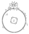
- a cable drum 1 with a cable drum is designated, which is rotatably mounted on a journal 3 connected to a fixed flange wall 2.
- a band 5 consisting of a sheet steel strip.
- the band 5 has a loop 6, with which the band 5 is fastened to a first pin 7 connected to the flange wall 2.
- the band 5 is integrally connected to an arcuate leaf spring 8.
- the leaf spring 8 also has a loop 9 at its free end, with which it is attached to a second pin 10 connected to the flange wall 2.
- the end 11 of the leaf spring 8 connected to the band 5 rests on an axial projection 12 provided on the flange wall 2.
- a release button 13 is attached over the curvature of the leaf spring 8. The release button 13 is pushed back into its rest position either by the force of the leaf spring 8 or by an additionally provided coil spring 14.
- the braking device described consists of only a single component, which by up put on the provided on the flange wall 2 pins 7 and 10 is already functional mounted.
Landscapes
- Engineering & Computer Science (AREA)
- Mechanical Engineering (AREA)
- Braking Arrangements (AREA)
- Unwinding Of Filamentary Materials (AREA)
- Tension Adjustment In Filamentary Materials (AREA)
- Storage Of Web-Like Or Filamentary Materials (AREA)
Description
- Die Erfindung betrifft eine Bremseinrichtung für eine Kabeltrommel, die an einer feststehenden Flanschwand drehbar gelagert und durch eine Spiralfeder in Aufwickelrichtung antreibbar ist, bei welcher Bremseinrichtung ein Bremselement vorgesehen ist, das direkt auf den Umfangsrand einer der Kabeltrommelwände wirkt.
- Eine solche Bremseinrichtung ist durch die DE-AS 2641 800 bekannt. Bei dieser bekannten Einrichtung ist ein schwenkbar angeordnetes Tragelement vorgesehen, welches zwei sich in Aufwickelrichtung der Kabeltrommel verjüngende Federschenkel aufweist. Die beiden Federschenkel liegen zu beiden Seiten eines an der einen Kabeltrommelwand angeformten, axial nach außen gerichteten Randes. Die Federschenkel bilden zusammen mit dem Rand zwei keilförmige Räume, in denen jeweils eine Hohlrolle angeordnet ist. Eine durch eine Blattfeder in Aufwickelrichtung verschwenkte Scheibe greift mit zwei Stiften in die Hohlräume der Rollen und zieht diese ebenfalls in Aufwickelrichtung. Dabei werden die Hohlrollen zwischen den sich verjüngenden Federschenkeln und dem Rand der Kabeltrommel festgeklemmt, so daß die Kabeltrommel entgegen der Kraft der Spiralfeder an einer Drehbewegung in Aufwickelrichtung gehindert wird. Zum Lösen der Bremseinrichtung kann die Scheibe mittels einer Lösetaste entgegen der Kraft der Blattfeder verschwenkt werden. Hierdurch werden die Hohlrollen ebenfalls in entgegengesetzter Richtung mitgenommen und geben die Kabeltrommel für eine Drehbewegung in Aufwickelrichtung frei. Die bekannte Bremseinrichtung besteht aus einer Vielzahl von Elementen, deren Montage viel Zeit beansprucht.
- Der Erfindung liegt die Aufgabe zugrunde, eine Bremseinrichtung zu schaffen, die nur aus wenigen Teilen besteht und dadurch leichter und schneller zu montieren ist.
- Die Lösung der gestellten Aufgabe gelingt nach der Erfindung dadurch, daß als Bremselement ein mit seinem einen Ende an der Flanschwand befestigtes Band vorgesehen ist, welches den Umfangsrand zumindest teilweise umschlingt und dessen anderes Ende mit einer ebenfalls an der Flanschwand befestigten Zugfeder verbunden ist. Ein solches Band läßt sich in einfacher Weise um die Kabeltrommel legen, wobei die Befestigung am Ende und die Verbindung der Zugfeder durch bloßes Einhängen mittels Schlaufen und Haken erfolgen kann. Zum Lösen der Bremse wird die Zugfeder mit Hilfe einer Lösetaste entspannt. Dadurch liegt das Band nur noch locker auf der Kabeltrommelwand auf und die Kabeltrommel kann durch die Spiralfeder in Aufwickelrichtung gedreht werden.
- Eine weitere Vereinfachung der Bremseinrichtung gelingt nach einer Ausgestaltung der Erfindung dadurch, daß das Band aus einem kreisbogenförmig gebogenen Stahlblechstreifen besteht, an dem einstückig eine bogenförmige Blattfeder angeformt ist. Die Bremseinrichtung besteht damit nur noch aus einem einzigen Bauteil.
- Für das Lösen der Bremseinrichtung kommt man dadurch ohne besonderen konstruktiven Aufwand aus, daß die Blattfeder radial nach außen gewölbt ist und mit ihrem mit dem Stahlblechstreifen verbundenen Ende auf einem Axialvorsprung der Flanschwand aufliegt und daß ferner über der Wölbung eine gegen diese drückbare Lösetaste angeordnet ist.
- Anhand eines in der Zeichnung dargestellten Ausführungsbeispiels wird der Anmeldungsgegenstand nachfolgend näher beschrieben.
- Mit 1 ist eine Kabeltrommel bezeichnet, die auf einem mit einer feststehenden Flanschwand 2 verbundenen Lagerzapfen 3 drehbar gelagert ist. Um den Umfangsrand 4 der einen Kabeltrommelwand ist ein aus einem Stahlblechstreifen bestehendes Band 5 geschlungen. An seinem einen Ende weist das Band 5 eine Schlaufe 6 auf, mit der das Band 5 an einem ersten mit der Flanschwand 2 verbundenen Zapfen 7 befestigt ist. Mit seinem anderen Ende ist das Band 5 einstückig mit einer bogenförmigen Blattfeder 8 verbunden. Die Blattfeder 8 weist an ihrem freien Ende ebenfalls eine Schlaufe 9 auf, mit der sie an einem zweiten mit der Flanschwand 2 verbundenen Zapfen 10 befestigt ist. Das mit dem Band 5 verbundene Ende 11 der Blattfeder 8 ruht auf einem an der Flanschwand 2 vorgesehenen Axialvorsprung 12 auf. Über der Wölbung der Blattfeder 8 ist eine Lösetaste 13 angebracht. Die Lösetaste 13 wird entweder durch die Kraft der Blattfeder 8 oder durch eine zusätzlich vorgesehene Schraubenfeder 14 wieder in ihre Ruhelage gedrängt.
- Die Bremseinrichtung arbeitet wie folgt:
- Durch die Blattfeder 8, welche eine Zugkraft auf das Band 5 ausübt, legt sich das Band 5 gegen den Umfangsrand 4 der betreffenden Kabeltrommelwand. Dadurch wird die Kabeltrommel an einer Drehbewegung in der durch einen Pfeil 15 gekennzeichneten Drehrichtung gehindert. Bei einer Drehbewegung in Richtung des Pfeils 15 wird das Band 5 durch die Reibungskräfte sogar noch fester an den Umfangsrand der Kabeltrommelwand angepreßt. Um eine Drehbewegung der Kabeltrommel in Richtung des Pfeiles 15 zu ermöglichen, wird die Lösetaste 13 in Richtung des Pfeiles 16 gedrückt. Durch den Druck auf die Wölbung der Blattfeder 8 gleitet deren mit dem Band 5 verbundenes Ende 11 auf dem Axialvorsprung 12 entlang. Hierdurch wird das Band 5 gegenüber dem Umfangsrand 4 gelokkert, so daß sich nunmehr die Kabeltrommel 1 in der durch den Pfeil 15 gekennzeichneten Richtung drehen kann. Nach dem Loslassen der Lösetaste 13 wölbt sich die Blattfeder 8 wieder nach außen und zieht hierbei das Band 5 wieder gegen den Umfangsrand 4 der Kabeltrommel 1.
- Die beschriebene Bremseinrichtung besteht aus nur einem einzigen Bauteil, das durch Aufstecken auf die an der Flanschwand 2 vorgesehenen Zapfen 7 und 10 bereits funktionsfähig montiert ist.
Claims (4)
Priority Applications (1)
| Application Number | Priority Date | Filing Date | Title |
|---|---|---|---|
| AT83102610T ATE14517T1 (de) | 1982-03-29 | 1983-03-16 | Bremseinrichtung fuer eine kabeltrommel. |
Applications Claiming Priority (2)
| Application Number | Priority Date | Filing Date | Title |
|---|---|---|---|
| DE3211577A DE3211577C2 (de) | 1982-03-29 | 1982-03-29 | Bremseinrichtung für eine Kabeltrommel |
| DE3211577 | 1982-03-29 |
Publications (2)
| Publication Number | Publication Date |
|---|---|
| EP0090974A1 EP0090974A1 (de) | 1983-10-12 |
| EP0090974B1 true EP0090974B1 (de) | 1985-07-31 |
Family
ID=6159628
Family Applications (1)
| Application Number | Title | Priority Date | Filing Date |
|---|---|---|---|
| EP83102610A Expired EP0090974B1 (de) | 1982-03-29 | 1983-03-16 | Bremseinrichtung für eine Kabeltrommel |
Country Status (3)
| Country | Link |
|---|---|
| EP (1) | EP0090974B1 (de) |
| AT (1) | ATE14517T1 (de) |
| DE (2) | DE3211577C2 (de) |
Families Citing this family (4)
| Publication number | Priority date | Publication date | Assignee | Title |
|---|---|---|---|---|
| DE3316977A1 (de) * | 1983-05-09 | 1984-11-15 | Siemens AG, 1000 Berlin und 8000 München | Aufwickelvorrichtung fuer strangfoermiges wickelgut |
| GB2273753B (en) * | 1992-12-17 | 1996-03-27 | Goblin Ltd | Safety mechanism for power tool |
| DE19705016A1 (de) * | 1997-02-10 | 1998-08-13 | Bosch Siemens Hausgeraete | Bremseinrichtung für eine Kabeltrommel |
| CN110194396B (zh) * | 2019-05-28 | 2024-12-10 | 青岛电气工程安装有限公司送变电分公司 | 一种带有剪式千斤顶结构的线缆盘制动装置 |
Family Cites Families (4)
| Publication number | Priority date | Publication date | Assignee | Title |
|---|---|---|---|---|
| US2283784A (en) * | 1941-01-21 | 1942-05-19 | Roy O Billings | Tag-line reel |
| DE1574382B1 (de) * | 1967-10-14 | 1971-08-26 | Licentia Gmbh | Bremsvorrichtung |
| BE795831A (fr) * | 1972-03-04 | 1973-06-18 | Vorwerk & Co Elektrowerke Kg | Dispositif d'enroulement pour le cable, plus particulierement des aspirateurs |
| NL7511418A (nl) * | 1975-09-29 | 1977-03-31 | Philips Nv | Reminrichting voor kabeltrommel. |
-
1982
- 1982-03-29 DE DE3211577A patent/DE3211577C2/de not_active Expired
-
1983
- 1983-03-16 DE DE8383102610T patent/DE3360457D1/de not_active Expired
- 1983-03-16 EP EP83102610A patent/EP0090974B1/de not_active Expired
- 1983-03-16 AT AT83102610T patent/ATE14517T1/de not_active IP Right Cessation
Also Published As
| Publication number | Publication date |
|---|---|
| ATE14517T1 (de) | 1985-08-15 |
| DE3211577C2 (de) | 1984-12-13 |
| DE3211577A1 (de) | 1983-10-13 |
| EP0090974A1 (de) | 1983-10-12 |
| DE3360457D1 (en) | 1985-09-05 |
Similar Documents
| Publication | Publication Date | Title |
|---|---|---|
| DE2517359C2 (de) | Kurbelbetätigtes Bandmaß | |
| DE2818944C2 (de) | Vorrichtung zum Verklemmen und Lösen eines frei drehbaren Rotors | |
| DE1575787B1 (de) | In beiden Drehrichtungen wirkende Klemmrollen-Freilaufkupplung | |
| EP0090974B1 (de) | Bremseinrichtung für eine Kabeltrommel | |
| DE2641800C3 (de) | Bremsvorrichtung für eine Kabeltrommel | |
| DE2539281B2 (de) | ||
| DE3204652C2 (de) | ||
| DE825793C (de) | Entwicklungsspule fuer photographische Filmbaender | |
| DE19831098A1 (de) | Freilaufkupplung | |
| DE69025835T2 (de) | Plattenaufwicklungsvorrichtung | |
| CH651898A5 (de) | Halter fuer einen rollenfoermigen nockenfolger einer trommelbremse. | |
| DE2249872C3 (de) | Vorrichtung zum Anlegen des vorderen Bandendes bandförmigen Wickelgutes an den Kern einer Aufwickelspule | |
| DE2110408C2 (de) | Spiralfedergetriebene Wickelvorrichtung | |
| EP0124823A1 (de) | Aufwickelvorrichtung für strangförmiges Wickelgut | |
| DE1425207B2 (de) | Scheibenreibungskupplung | |
| DE2308755A1 (de) | Huelsenspannkupplung fuer die achslose aufnahme von zylindrischen rotationskoerpern | |
| DE8208914U1 (de) | Kabelaufrollvorrichtung mit einer Bremseinrichtung für die Kabeltrommel | |
| DE3829704A1 (de) | Spann- und fuehrungsvorrichtung fuer wickelhuelsen | |
| DE2626796B2 (de) | Antriebseinrichtung fuer ein kassetten-bandgeraet | |
| AT167554B (de) | Klinkengesperre | |
| DE8133765U1 (de) | Bremsvorrichtung fuer eine drehbar in oder an einem gehaeuse angeordnete kabeltrommel | |
| DE2706101C2 (de) | Halterung für den Spulenkern einer Etikettenbandrolle | |
| AT242512B (de) | Projektionsgerät mit automatischer Filmeinlegung | |
| DE1921344C (de) | Kerneinspannvorrichtung | |
| DE2613788A1 (de) | Zentrifugalkupplung |
Legal Events
| Date | Code | Title | Description |
|---|---|---|---|
| PUAI | Public reference made under article 153(3) epc to a published international application that has entered the european phase |
Free format text: ORIGINAL CODE: 0009012 |
|
| AK | Designated contracting states |
Designated state(s): AT DE FR NL SE |
|
| 17P | Request for examination filed |
Effective date: 19831026 |
|
| GRAA | (expected) grant |
Free format text: ORIGINAL CODE: 0009210 |
|
| AK | Designated contracting states |
Designated state(s): AT DE FR NL SE |
|
| REF | Corresponds to: |
Ref document number: 14517 Country of ref document: AT Date of ref document: 19850815 Kind code of ref document: T |
|
| REF | Corresponds to: |
Ref document number: 3360457 Country of ref document: DE Date of ref document: 19850905 |
|
| ET | Fr: translation filed | ||
| PLBE | No opposition filed within time limit |
Free format text: ORIGINAL CODE: 0009261 |
|
| STAA | Information on the status of an ep patent application or granted ep patent |
Free format text: STATUS: NO OPPOSITION FILED WITHIN TIME LIMIT |
|
| 26N | No opposition filed | ||
| PGFP | Annual fee paid to national office [announced via postgrant information from national office to epo] |
Ref country code: AT Payment date: 19890224 Year of fee payment: 7 |
|
| PGFP | Annual fee paid to national office [announced via postgrant information from national office to epo] |
Ref country code: FR Payment date: 19890322 Year of fee payment: 7 |
|
| PGFP | Annual fee paid to national office [announced via postgrant information from national office to epo] |
Ref country code: SE Payment date: 19890330 Year of fee payment: 7 |
|
| PGFP | Annual fee paid to national office [announced via postgrant information from national office to epo] |
Ref country code: NL Payment date: 19890331 Year of fee payment: 7 |
|
| PG25 | Lapsed in a contracting state [announced via postgrant information from national office to epo] |
Ref country code: DE Effective date: 19891201 |
|
| PG25 | Lapsed in a contracting state [announced via postgrant information from national office to epo] |
Ref country code: AT Effective date: 19900316 |
|
| PG25 | Lapsed in a contracting state [announced via postgrant information from national office to epo] |
Ref country code: SE Effective date: 19900317 |
|
| PG25 | Lapsed in a contracting state [announced via postgrant information from national office to epo] |
Ref country code: NL Effective date: 19901001 |
|
| NLV4 | Nl: lapsed or anulled due to non-payment of the annual fee | ||
| PG25 | Lapsed in a contracting state [announced via postgrant information from national office to epo] |
Ref country code: FR Effective date: 19901130 |
|
| REG | Reference to a national code |
Ref country code: FR Ref legal event code: ST |
|
| EUG | Se: european patent has lapsed |
Ref document number: 83102610.9 Effective date: 19910110 |