EP0090346A2 - Anordnung einer Aufhängungslagerung - Google Patents
Anordnung einer Aufhängungslagerung Download PDFInfo
- Publication number
- EP0090346A2 EP0090346A2 EP83102901A EP83102901A EP0090346A2 EP 0090346 A2 EP0090346 A2 EP 0090346A2 EP 83102901 A EP83102901 A EP 83102901A EP 83102901 A EP83102901 A EP 83102901A EP 0090346 A2 EP0090346 A2 EP 0090346A2
- Authority
- EP
- European Patent Office
- Prior art keywords
- brackets
- pair
- transverse
- tension rod
- supporting assembly
- Prior art date
- Legal status (The legal status is an assumption and is not a legal conclusion. Google has not performed a legal analysis and makes no representation as to the accuracy of the status listed.)
- Withdrawn
Links
Images
Classifications
-
- B—PERFORMING OPERATIONS; TRANSPORTING
- B60—VEHICLES IN GENERAL
- B60G—VEHICLE SUSPENSION ARRANGEMENTS
- B60G21/00—Interconnection systems for two or more resiliently-suspended wheels, e.g. for stabilising a vehicle body with respect to acceleration, deceleration or centrifugal forces
- B60G21/02—Interconnection systems for two or more resiliently-suspended wheels, e.g. for stabilising a vehicle body with respect to acceleration, deceleration or centrifugal forces permanently interconnected
- B60G21/04—Interconnection systems for two or more resiliently-suspended wheels, e.g. for stabilising a vehicle body with respect to acceleration, deceleration or centrifugal forces permanently interconnected mechanically
- B60G21/05—Interconnection systems for two or more resiliently-suspended wheels, e.g. for stabilising a vehicle body with respect to acceleration, deceleration or centrifugal forces permanently interconnected mechanically between wheels on the same axle but on different sides of the vehicle, i.e. the left and right wheel suspensions being interconnected
- B60G21/055—Stabiliser bars
- B60G21/0551—Mounting means therefor
-
- B—PERFORMING OPERATIONS; TRANSPORTING
- B60—VEHICLES IN GENERAL
- B60G—VEHICLE SUSPENSION ARRANGEMENTS
- B60G21/00—Interconnection systems for two or more resiliently-suspended wheels, e.g. for stabilising a vehicle body with respect to acceleration, deceleration or centrifugal forces
- B60G21/02—Interconnection systems for two or more resiliently-suspended wheels, e.g. for stabilising a vehicle body with respect to acceleration, deceleration or centrifugal forces permanently interconnected
- B60G21/04—Interconnection systems for two or more resiliently-suspended wheels, e.g. for stabilising a vehicle body with respect to acceleration, deceleration or centrifugal forces permanently interconnected mechanically
- B60G21/05—Interconnection systems for two or more resiliently-suspended wheels, e.g. for stabilising a vehicle body with respect to acceleration, deceleration or centrifugal forces permanently interconnected mechanically between wheels on the same axle but on different sides of the vehicle, i.e. the left and right wheel suspensions being interconnected
- B60G21/055—Stabiliser bars
-
- B—PERFORMING OPERATIONS; TRANSPORTING
- B60—VEHICLES IN GENERAL
- B60G—VEHICLE SUSPENSION ARRANGEMENTS
- B60G3/00—Resilient suspensions for a single wheel
- B60G3/02—Resilient suspensions for a single wheel with a single pivoted arm
- B60G3/04—Resilient suspensions for a single wheel with a single pivoted arm the arm being essentially transverse to the longitudinal axis of the vehicle
- B60G3/06—Resilient suspensions for a single wheel with a single pivoted arm the arm being essentially transverse to the longitudinal axis of the vehicle the arm being rigid
-
- B—PERFORMING OPERATIONS; TRANSPORTING
- B60—VEHICLES IN GENERAL
- B60G—VEHICLE SUSPENSION ARRANGEMENTS
- B60G99/00—Subject matter not provided for in other groups of this subclass
-
- B—PERFORMING OPERATIONS; TRANSPORTING
- B62—LAND VEHICLES FOR TRAVELLING OTHERWISE THAN ON RAILS
- B62D—MOTOR VEHICLES; TRAILERS
- B62D21/00—Understructures, i.e. chassis frame on which a vehicle body may be mounted
- B62D21/11—Understructures, i.e. chassis frame on which a vehicle body may be mounted with resilient means for suspension, e.g. of wheels or engine; sub-frames for mounting engine or suspensions
-
- B—PERFORMING OPERATIONS; TRANSPORTING
- B60—VEHICLES IN GENERAL
- B60G—VEHICLE SUSPENSION ARRANGEMENTS
- B60G2202/00—Indexing codes relating to the type of spring, damper or actuator
- B60G2202/10—Type of spring
- B60G2202/13—Torsion spring
- B60G2202/135—Stabiliser bar and/or tube
-
- B—PERFORMING OPERATIONS; TRANSPORTING
- B60—VEHICLES IN GENERAL
- B60G—VEHICLE SUSPENSION ARRANGEMENTS
- B60G2204/00—Indexing codes related to suspensions per se or to auxiliary parts
- B60G2204/10—Mounting of suspension elements
- B60G2204/12—Mounting of springs or dampers
- B60G2204/122—Mounting of torsion springs
- B60G2204/1222—Middle mounts of stabiliser on vehicle body or chassis
-
- B—PERFORMING OPERATIONS; TRANSPORTING
- B60—VEHICLES IN GENERAL
- B60G—VEHICLE SUSPENSION ARRANGEMENTS
- B60G2204/00—Indexing codes related to suspensions per se or to auxiliary parts
- B60G2204/10—Mounting of suspension elements
- B60G2204/15—Mounting of subframes
-
- B—PERFORMING OPERATIONS; TRANSPORTING
- B60—VEHICLES IN GENERAL
- B60G—VEHICLE SUSPENSION ARRANGEMENTS
- B60G2206/00—Indexing codes related to the manufacturing of suspensions: constructional features, the materials used, procedures or tools
- B60G2206/01—Constructional features of suspension elements, e.g. arms, dampers, springs
- B60G2206/60—Subframe construction
- B60G2206/605—Flexible constructions
Definitions
- the present invention relates to a supporting assembly for a suspension to suspend the wheels of a vehicle, and more particularly to a compact and light suspension by which the vibration of the wheels can be absorbed while the vehicle is driving.
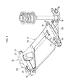
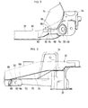
- FIG. 1 illustrates an example of a conventional supporting assembly 11, wherein a pair of tension rod brackets 15 are attached respectivery at one end thereof to the opposite ends of a transverse member 13.
- the supporting assembly 11 is placed under and elastically mounted to a body (not shown) through insultoars 17.
- a pair of tension rods 23 are attached at one end thereof to the outer ends of wheel supporting members 19 of transverse links 21.
- the tension rods 23 are supported at the other end therof by the other ends of the tension rod brackets 15.
- a wheel is rotatably mounted through each of the wheel supporting members 19 to the body.
- an improved supporting assembly for a suspension which comprises: a transverse member attached in a transverse direction to a vehicle body; a pair of tension rod brackets which are attached in the longitudinal direction of the body to the opposite ends of said transverse member; insulators which are mounted to the pair of tension rod brackets and through which said supporting assembly is elastically mounted under the body; a pair of tension rods each having one end thereof connected to each of the other ends of said tension rod brackets; a pair of transverse links extending outwardly from said transverse member, said tension rods being attached at the other end thereof to said transverse links, respectively; a stick-like reinforcing member the opposite ends of which are connected to said pair of tension rod brackets at positions spaced from said transverse member.
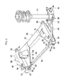
- FIG. 2 there is generally indicated by numeral 30 an embodiment of a supporting assembly for the suspension of an automobile comprising a transverse member 32 and a pair of tension rod brackets 34 which are attached to the opposite ends of a transverse member 32 in an automobile body.
- the support assembly is connected to the engine of the automobile through bed seats 74.
- a stabilizers 76 is mounted to the support assembly.
- the transverse member 32 is disposed perpendicularly to the longitudinal direction of the body (not shown).
- the pair of tension rod brackets 34 are welded and fixed respectively at one end thereof to the opposite ends of the transverse member 32 so that they extend in the longitudinal direction of the body.
- the supporting assembly 30 is elastically mounted to the body through insulators 36 which are attached to the opposite ends of the tension rod brackets 34.
- a wheel supporting members 38 is fixed to the outer edge of the respective transverse link 40.
- the transverse links 40 are swingingly attached to the opposite ends of the transverse member 32 through insulators (not shown).
- the wheel supporting member 38 comprises a spindle 64 for rotatably supporting a wheel (not shown) and a member for supporting the bottom portion of a hub and a suspension strut 44 affixed thereto.
- the upper end of the suspension strut 44 is fixed to the body not shown.
- a pair of rod receiving brackets 46 are mounted to the other ends of the tension rod brackets 34 remote from the transverse member 32, respectively.
- a pair of tension rods 48 are supported respectively atone end thereof by the rod receiving brackets 46 through insulators 50.
- the other end of each of the tension rods 48 is disposed outwardly from the tension rod bracket 34 in the transverse direction of the body and connected to the outer edge of the transverse link 40.
- a reinforcing member 60 extends between both of the opposed tension rod brackets 34.
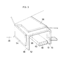
- This reinforcing member 60 is of a stick-like shape and has a circular cross section with the opposite end potions 62 and 64 thereof formed into a plate-like shape.
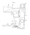
- a reinforcing brackets 52 is mounted to the inside of each of the tension rod brackets 34 at the other end thereof, that is to say, near the rod receiving bracket 46.
- the reinforcing bracket 52 comprises a top plate 66, a front side plate 68 and rear side plate 70.
- the top plate 66 is bonded, e.g. by welding, to the lower surface of a shelf plate 56 overhanging inwardly from the tension rod bracket 34.
- the front side plate 68 is bonded to the inner surface of a receiving bracket 54.
- the bracket 54 is attached to and extends inwardly from the rod receiving bracket 46.
- the rear side plate 70 is bonded to the inner surface of a falling portion 72 of the shelf plate 56.
- the reinforcing bracket 52 is surrounded and strongly supported by the shelf plate 56, the falling portion 72 and the receiving bracket 54.
- the afore-mentioned plate-like end portions 62 and 64 of the reinforcing member 60 are thus bonded to the top plates 66 and the front side plate 68 of the reinforcing brackets 52, respectively.
- shock force When braking suddenly during driving, shock force will be exerted in the front and rear directions to the transverse links 40 through the spindles 42 from the wheels (not shown).
- the shock forces are transmitted to the other ends of the tension rod bracket 34 through the tension rods 48, the insulators 36 and the rod receiving brackets 46.
- the shock forces are further transmitted from the tension rod brackets 34 securely to the reinforcing brackets 52, and received by the stick-like reinforcing member 60 at the opposite ends thereof substantially equally in the opposed directions.
- the shock forces transmitted to the other ends of the tension rod brackets 34 are offset through the member 60. Therefore, no large bending moment occurs in the transverse member 32.
- the shock forces applied from the tension rods 48 to the rod receiving bracket 46 are securely transmitted to the reinforcing member 60 through the receiving brackets 54 integrally connected to the rod receiving brackets 46.
- the reinforcing member 60 may be formed by a channel material or angle material, etc. in place of the stick-like member having a circular cross section used in the above mentioned enbodiment.
- the reinforcing member 60 is attached to the tension rod brackets 34 through the reinforcing brackets 52, it may be attached directly to the brackets 34. It is not always necessary to provide the receiving brackets 54 for assuring the transmission of the shock forces to the reinforcing member 60.
- the end portions 62 of the reinforcing member 60 are connected to the bracket 34 at positions close to the rod receiving brackets 46 which support the tension rods 48 in the present embodiment. However, it is possible to dispose the end portions 62 at any suitable locations.
- the shock forces transmitted from the wheels through the tension rods to the tension rod brackets can be received and supported by the reinforcing member. Accordingly, the tension rod brackets do not deform so largely, so that any large bending moment in the transverse member which would otherwise be caused by the tension rod brackets can be avoided. Therefore, it is possible to prevent the degradation in noise and vibration absorbing property caused by the deformation of the supporting assembly while maintaining the supporting assembly as well as the transverse member compact and light, thereby providing the supporting assembly at a low price and with an increased engine oil pan capacity and it is also possible to keep the supporting assembly sufficiently high from the ground.
- the shock forces from the tension rods can be securely received by the reinforcing member which is provided between the tension rod branckets at the ends thereof remote from the transverse member. It is possible to make the reinforcing member light in weight by using a stick-like reinforcing member.
- the shock forces from the tension rods can be securely transmitted to the reinforcing member which is connected to the reinforcing brackets for reinforcing the tension rod brackets.
- the shock forces can be securely transmitted to the reinforcing member which is connected to the receiving brackets affixed to the reinforcing brackets.
Landscapes
- Engineering & Computer Science (AREA)
- Mechanical Engineering (AREA)
- Chemical & Material Sciences (AREA)
- Combustion & Propulsion (AREA)
- Transportation (AREA)
- Body Structure For Vehicles (AREA)
- Vehicle Body Suspensions (AREA)
Applications Claiming Priority (2)
| Application Number | Priority Date | Filing Date | Title |
|---|---|---|---|
| JP57051188A JPS58170607A (ja) | 1982-03-31 | 1982-03-31 | 懸架装置の支持メンバ |
| JP51188/82 | 1982-03-31 |
Publications (2)
| Publication Number | Publication Date |
|---|---|
| EP0090346A2 true EP0090346A2 (de) | 1983-10-05 |
| EP0090346A3 EP0090346A3 (de) | 1986-03-12 |
Family
ID=12879886
Family Applications (1)
| Application Number | Title | Priority Date | Filing Date |
|---|---|---|---|
| EP83102901A Withdrawn EP0090346A3 (de) | 1982-03-31 | 1983-03-23 | Anordnung einer Aufhängungslagerung |
Country Status (3)
| Country | Link |
|---|---|
| US (1) | US4501436A (de) |
| EP (1) | EP0090346A3 (de) |
| JP (1) | JPS58170607A (de) |
Cited By (4)
| Publication number | Priority date | Publication date | Assignee | Title |
|---|---|---|---|---|
| US4501436A (en) * | 1982-03-31 | 1985-02-26 | Nissan Motor Company, Limited | Supporting assembly for a suspension |
| FR2606333A1 (fr) * | 1986-11-07 | 1988-05-13 | Renault | Structure de train pour suspensions a roues independantes |
| DE19961669A1 (de) * | 1999-12-21 | 2001-06-28 | Man Nutzfahrzeuge Ag | Längslenkerbock in Nutzfahrzeugen |
| CN102092380A (zh) * | 2011-01-04 | 2011-06-15 | 安徽福马车桥有限公司 | 汽车驱动桥制动气室和推力杆的组合式支架 |
Families Citing this family (19)
| Publication number | Priority date | Publication date | Assignee | Title |
|---|---|---|---|---|
| JPS62105709A (ja) * | 1985-11-05 | 1987-05-16 | Toyota Motor Corp | 車両のサスペンシヨン |
| JPH01126881U (de) * | 1988-02-23 | 1989-08-30 | ||
| JP2601866Y2 (ja) * | 1988-06-02 | 1999-12-06 | 本田技研工業株式会社 | 車体のサブフレーム |
| JP3788175B2 (ja) * | 2000-03-13 | 2006-06-21 | スズキ株式会社 | サスペンションフレーム構造 |
| DE10153272B4 (de) * | 2000-11-01 | 2009-04-16 | Honda Giken Kogyo K.K. | Druckguss-Hilfsrahmen |
| JP3861587B2 (ja) * | 2000-11-07 | 2006-12-20 | スズキ株式会社 | フロントサスペンションのサブフレーム構造 |
| KR100488598B1 (ko) * | 2002-04-11 | 2005-05-11 | 기아자동차주식회사 | 텐션로드를 구비한 차량의 서스펜션 |
| TWI231283B (en) * | 2002-12-25 | 2005-04-21 | Mitsubishi Motors Corp | Suspension cross member |
| US7429054B1 (en) * | 2005-12-14 | 2008-09-30 | Heckethorn Products, Inc. | Non-drop torsion bar bracket and assembly |
| US7748727B2 (en) * | 2006-06-13 | 2010-07-06 | Nissan Motor Co., Ltd. | Suspension structure |
| JP4970895B2 (ja) * | 2006-10-25 | 2012-07-11 | ヤマハ発動機株式会社 | 車体用振動減衰装置の取付構造 |
| DE102009020305A1 (de) * | 2008-05-26 | 2009-12-03 | Ksm Castings Gmbh | Achsträger für Kraftfahrzeuge |
| JP5084883B2 (ja) * | 2009-12-28 | 2012-11-28 | 株式会社ヨロズ | サスペンションのサブフレーム |
| FR2959450B1 (fr) * | 2010-04-29 | 2013-03-08 | Peugeot Citroen Automobiles Sa | Dispositif de support de suspension |
| DE102012020612A1 (de) * | 2012-10-19 | 2014-04-24 | Audi Ag | Achsträger für ein Kraftfahrzeug |
| US8875834B1 (en) * | 2013-04-12 | 2014-11-04 | GM Global Technology Operations LLC | Increased stiffness underbody panel |
| DE102013020565B3 (de) * | 2013-12-09 | 2014-11-27 | Audi Ag | Hilfsrahmenanordnung für ein Fahrzeug |
| DE102017218276A1 (de) * | 2017-10-12 | 2019-04-18 | Bayerische Motoren Werke Aktiengesellschaft | Achsträger eines Fahrzeugs mit einem Lagerteil für einen Querstabilisator |
| JP7400238B2 (ja) * | 2019-07-24 | 2023-12-19 | マツダ株式会社 | サブフレーム構造 |
Citations (6)
| Publication number | Priority date | Publication date | Assignee | Title |
|---|---|---|---|---|
| FR2150479A1 (de) * | 1971-08-25 | 1973-04-06 | Daimler Benz Ag | |
| US3913696A (en) * | 1974-05-08 | 1975-10-21 | Ford Motor Co | Chassis construction for a motor vehicle |
| DE2659081A1 (de) * | 1976-12-27 | 1978-07-06 | Volkswagenwerk Ag | Hilfsrahmen |
| US4258820A (en) * | 1978-09-04 | 1981-03-31 | Honda Giken Kogyo Kabushiki Kaisha | Sub-frame supporting apparatus for an automobile |
| GB2089744A (en) * | 1980-12-23 | 1982-06-30 | Daimler Benz Ag | A sub-frame for a motor vehicle |
| US4392545A (en) * | 1980-04-12 | 1983-07-12 | Toyo Kogyo Co., Ltd. | Engine mounting structure for an automobile body |
Family Cites Families (4)
| Publication number | Priority date | Publication date | Assignee | Title |
|---|---|---|---|---|
| US3037762A (en) * | 1960-08-29 | 1962-06-05 | Gen Motors Corp | Trailing arm torsion bar suspension |
| US3218053A (en) * | 1962-10-26 | 1965-11-16 | Russell L Shreve | Vehicle suspension including anti-roll bar assembly |
| JPS5434150Y2 (de) * | 1975-03-24 | 1979-10-19 | ||
| JPS58170607A (ja) * | 1982-03-31 | 1983-10-07 | Nissan Motor Co Ltd | 懸架装置の支持メンバ |
-
1982
- 1982-03-31 JP JP57051188A patent/JPS58170607A/ja active Granted
-
1983
- 1983-03-23 EP EP83102901A patent/EP0090346A3/de not_active Withdrawn
- 1983-03-28 US US06/479,516 patent/US4501436A/en not_active Expired - Lifetime
Patent Citations (6)
| Publication number | Priority date | Publication date | Assignee | Title |
|---|---|---|---|---|
| FR2150479A1 (de) * | 1971-08-25 | 1973-04-06 | Daimler Benz Ag | |
| US3913696A (en) * | 1974-05-08 | 1975-10-21 | Ford Motor Co | Chassis construction for a motor vehicle |
| DE2659081A1 (de) * | 1976-12-27 | 1978-07-06 | Volkswagenwerk Ag | Hilfsrahmen |
| US4258820A (en) * | 1978-09-04 | 1981-03-31 | Honda Giken Kogyo Kabushiki Kaisha | Sub-frame supporting apparatus for an automobile |
| US4392545A (en) * | 1980-04-12 | 1983-07-12 | Toyo Kogyo Co., Ltd. | Engine mounting structure for an automobile body |
| GB2089744A (en) * | 1980-12-23 | 1982-06-30 | Daimler Benz Ag | A sub-frame for a motor vehicle |
Cited By (5)
| Publication number | Priority date | Publication date | Assignee | Title |
|---|---|---|---|---|
| US4501436A (en) * | 1982-03-31 | 1985-02-26 | Nissan Motor Company, Limited | Supporting assembly for a suspension |
| FR2606333A1 (fr) * | 1986-11-07 | 1988-05-13 | Renault | Structure de train pour suspensions a roues independantes |
| EP0270406A1 (de) * | 1986-11-07 | 1988-06-08 | Regie Nationale Des Usines Renault | Achsanordnung für unabhängige Radaufhängung |
| DE19961669A1 (de) * | 1999-12-21 | 2001-06-28 | Man Nutzfahrzeuge Ag | Längslenkerbock in Nutzfahrzeugen |
| CN102092380A (zh) * | 2011-01-04 | 2011-06-15 | 安徽福马车桥有限公司 | 汽车驱动桥制动气室和推力杆的组合式支架 |
Also Published As
| Publication number | Publication date |
|---|---|
| JPH021684B2 (de) | 1990-01-12 |
| JPS58170607A (ja) | 1983-10-07 |
| EP0090346A3 (de) | 1986-03-12 |
| US4501436A (en) | 1985-02-26 |
Similar Documents
| Publication | Publication Date | Title |
|---|---|---|
| US4501436A (en) | Supporting assembly for a suspension | |
| EP1037756B1 (de) | Verjüngte gebogene blattfeder für lkw-aufhängungen | |
| US6357772B1 (en) | Rear wheel suspension and subframe for the front or rear wheel suspension of a motor vehicle | |
| EP0794075A2 (de) | Verformbarer Aufhängungslenker für Kraftfahrzeuge | |
| EP0716943A1 (de) | Befestigungsbügel | |
| GB2122555A (en) | An assembly for the vibration isolation attachment of a subframe or component holder to the main frame of a vehicle | |
| US5267623A (en) | Mounting structure for a power unit of an automobile | |
| US5823287A (en) | Mounting assembly for a transmission cross member of a motor vehicle | |
| EP0170220B1 (de) | Hinterradaufhängungssystem für Fahrzeug | |
| GB2300162A (en) | Rear suspension system for vehicle | |
| EP0301782B1 (de) | Aufhängeeinheit für Fahrzeugrad | |
| EP0066858A2 (de) | Aufhängungsaufbau für ein Kraftfahrzeug | |
| GB2131367A (en) | Vehicle differential gear housing supporting apparatus | |
| US3101126A (en) | Vehicle power transmission unit mounting | |
| JP2623864B2 (ja) | 従動輪用リジッドサスペンションのアクスル構造 | |
| JP2993199B2 (ja) | サスペンションアッパサポート構造 | |
| JP3264416B2 (ja) | 液圧緩衝器の取付ブラケット | |
| US3161253A (en) | Drive line support means | |
| US2738985A (en) | Motor vehicle rear wheel suspension mechanism | |
| KR200206928Y1 (ko) | 자동차 현가장치의 로워 컨트롤 아암 | |
| JP2626290B2 (ja) | 鉄道車両用軸箱装置 | |
| US6318709B1 (en) | Upper seat structure for rear coil spring | |
| KR0177456B1 (ko) | 차량 서스펜션의 횡강성 향상 방법 | |
| KR200160496Y1 (ko) | 차량용 추진축의 고정구조 | |
| JPS6323221Y2 (de) |
Legal Events
| Date | Code | Title | Description |
|---|---|---|---|
| PUAI | Public reference made under article 153(3) epc to a published international application that has entered the european phase |
Free format text: ORIGINAL CODE: 0009012 |
|
| 17P | Request for examination filed |
Effective date: 19830323 |
|
| AK | Designated contracting states |
Designated state(s): DE FR GB |
|
| RAP1 | Party data changed (applicant data changed or rights of an application transferred) |
Owner name: NISSAN MOTOR CO., LTD. |
|
| PUAL | Search report despatched |
Free format text: ORIGINAL CODE: 0009013 |
|
| AK | Designated contracting states |
Kind code of ref document: A3 Designated state(s): DE FR GB |
|
| STAA | Information on the status of an ep patent application or granted ep patent |
Free format text: STATUS: THE APPLICATION HAS BEEN WITHDRAWN |
|
| 18W | Application withdrawn |
Withdrawal date: 19870330 |
|
| RIN1 | Information on inventor provided before grant (corrected) |
Inventor name: ISHIDA, TAKASHI |