EP0086484A1 - Aufbewahrungskassette für plattenförmige Informationsträger hoher Speicherdichte - Google Patents
Aufbewahrungskassette für plattenförmige Informationsträger hoher Speicherdichte Download PDFInfo
- Publication number
- EP0086484A1 EP0086484A1 EP83101404A EP83101404A EP0086484A1 EP 0086484 A1 EP0086484 A1 EP 0086484A1 EP 83101404 A EP83101404 A EP 83101404A EP 83101404 A EP83101404 A EP 83101404A EP 0086484 A1 EP0086484 A1 EP 0086484A1
- Authority
- EP
- European Patent Office
- Prior art keywords
- information carrier
- pin
- storage cassette
- cassette according
- cover part
- Prior art date
- Legal status (The legal status is an assumption and is not a legal conclusion. Google has not performed a legal analysis and makes no representation as to the accuracy of the status listed.)
- Granted
Links
- 238000003860 storage Methods 0.000 title claims abstract description 52
- 239000000969 carrier Substances 0.000 title claims abstract description 7
- 229920003023 plastic Polymers 0.000 claims description 4
- 230000000694 effects Effects 0.000 claims 1
- 238000013461 design Methods 0.000 description 13
- 238000004519 manufacturing process Methods 0.000 description 5
- 238000013459 approach Methods 0.000 description 2
- 238000011161 development Methods 0.000 description 2
- 239000000463 material Substances 0.000 description 2
- 238000004806 packaging method and process Methods 0.000 description 2
- 239000004033 plastic Substances 0.000 description 2
- 230000000630 rising effect Effects 0.000 description 2
- 239000000853 adhesive Substances 0.000 description 1
- 230000001070 adhesive effect Effects 0.000 description 1
- 239000013013 elastic material Substances 0.000 description 1
- 239000004744 fabric Substances 0.000 description 1
- 238000010097 foam moulding Methods 0.000 description 1
- 238000001746 injection moulding Methods 0.000 description 1
- 238000003780 insertion Methods 0.000 description 1
- 230000037431 insertion Effects 0.000 description 1
- 238000002372 labelling Methods 0.000 description 1
- 239000013518 molded foam Substances 0.000 description 1
- 239000002985 plastic film Substances 0.000 description 1
- 229920006255 plastic film Polymers 0.000 description 1
- 238000003825 pressing Methods 0.000 description 1
- 239000000243 solution Substances 0.000 description 1
- 230000007704 transition Effects 0.000 description 1
Images


Classifications
-
- G—PHYSICS
- G11—INFORMATION STORAGE
- G11B—INFORMATION STORAGE BASED ON RELATIVE MOVEMENT BETWEEN RECORD CARRIER AND TRANSDUCER
- G11B33/00—Constructional parts, details or accessories not provided for in the other groups of this subclass
- G11B33/02—Cabinets; Cases; Stands; Disposition of apparatus therein or thereon
- G11B33/04—Cabinets; Cases; Stands; Disposition of apparatus therein or thereon modified to store record carriers
- G11B33/0405—Cabinets; Cases; Stands; Disposition of apparatus therein or thereon modified to store record carriers for storing discs
- G11B33/0411—Single disc boxes
- G11B33/0422—Single disc boxes for discs without cartridge
- G11B33/0427—Single disc boxes for discs without cartridge comprising centre hole locking means
-
- B—PERFORMING OPERATIONS; TRANSPORTING
- B65—CONVEYING; PACKING; STORING; HANDLING THIN OR FILAMENTARY MATERIAL
- B65D—CONTAINERS FOR STORAGE OR TRANSPORT OF ARTICLES OR MATERIALS, e.g. BAGS, BARRELS, BOTTLES, BOXES, CANS, CARTONS, CRATES, DRUMS, JARS, TANKS, HOPPERS, FORWARDING CONTAINERS; ACCESSORIES, CLOSURES, OR FITTINGS THEREFOR; PACKAGING ELEMENTS; PACKAGES
- B65D85/00—Containers, packaging elements or packages, specially adapted for particular articles or materials
- B65D85/54—Containers, packaging elements or packages, specially adapted for particular articles or materials for articles of special shape not otherwise provided for
- B65D85/544—Containers, packaging elements or packages, specially adapted for particular articles or materials for articles of special shape not otherwise provided for for gramophone records
-
- G—PHYSICS
- G11—INFORMATION STORAGE
- G11B—INFORMATION STORAGE BASED ON RELATIVE MOVEMENT BETWEEN RECORD CARRIER AND TRANSDUCER
- G11B23/00—Record carriers not specific to the method of recording or reproducing; Accessories, e.g. containers, specially adapted for co-operation with the recording or reproducing apparatus ; Intermediate mediums; Apparatus or processes specially adapted for their manufacture
- G11B23/02—Containers; Storing means both adapted to cooperate with the recording or reproducing means
- G11B23/03—Containers for flat record carriers
- G11B23/032—Containers for flat record carriers for rigid discs
-
- G—PHYSICS
- G11—INFORMATION STORAGE
- G11B—INFORMATION STORAGE BASED ON RELATIVE MOVEMENT BETWEEN RECORD CARRIER AND TRANSDUCER
- G11B33/00—Constructional parts, details or accessories not provided for in the other groups of this subclass
- G11B33/02—Cabinets; Cases; Stands; Disposition of apparatus therein or thereon
- G11B33/04—Cabinets; Cases; Stands; Disposition of apparatus therein or thereon modified to store record carriers
- G11B33/0405—Cabinets; Cases; Stands; Disposition of apparatus therein or thereon modified to store record carriers for storing discs
- G11B33/0461—Disc storage racks
- G11B33/0472—Disc storage racks for discs without cartridge
- G11B33/0477—Disc storage racks for discs without cartridge comprising centre hole locking means
Definitions
- the invention relates to a storage cassette, consisting at least of a flat, box-shaped base part and a removable or hinged cover part closing this base part at the top.
- cassettes made of cardboard or plastic which are preferably provided for the storage of normal records, are generally unsuitable for the storage of disk-shaped information carriers of high storage density, such as those represented by an optically readable video disk or an optically readable digital record.
- disk-shaped information carriers of high storage density such as those represented by an optically readable video disk or an optically readable digital record.
- Such a storage cassette basically offers a certain protection against damage to the contents, adequate protection against delay due to high demands on the freedom from delay cannot be achieved.
- care must also be taken to ensure that any warping of the cassette is not transferred to the disk inserted in the cassette.
- the invention is based on the object of specifying a further solution for a storage cassette of the type mentioned in the introduction, which also makes it possible to store the information carrier in single containers.
- this object is achieved according to the invention in that for storing plate-shaped information carriers with a high storage density, in particular digital records, the bottom of the Bottom part for storage of the information carrier exclusively in the center area free of traces of information has a support which is higher than the actual base surface and has a central pin arrangement which extends over the top of the support and that the pin arrangement adapted to the center hole diameter of the information carrier engages in the center hole of the information carrier when the information carrier is in the stored state.
- the invention is based on the essential finding that optimum security against warping of an information carrier is given by the fact that it is only stored in the central area of the storage cassette, ie the outer plate area, including the area which has the information track spiral, is free-floating.
- the distance of the stored information carrier to the cassette bottom and to the cassette cover in the area outside the support is expediently dimensioned in such a way that contact of the information carrier with the base part and / or the cover part is reliably avoided, taking into account maximum permissible distortion tolerances of both the information carrier and the cassette housing .
- the information carrier stored in the cassette can be fixed by suitable design or by resilient properties of the pin arrangement. Advantageous embodiments of this are given in claims 4 to 8.
- Another advantageous possibility of fixing the stored information carrier in the cassette is to provide a further raised support on the inside of the cover part, which is dimensioned such that the information carrier is clamped in its central region between the two supports in the closed state of the cassette.
- Appropriate configurations for this are specified in claims 9 and 10.
- the base part and the cover part can be separated from one another. In this case, only for their mutual fixation in the assembled state on the bottom part and on the cover part are assigned to each other associated recesses and lugs. For various applications, however, it makes sense to firmly connect the base and cover parts on one side with a hinge.
- the base part and the cover part can represent a pallet which accommodates the information carrier and which, if appropriate, is placed in a box-shaped container together with a booklet or. is inserted. Further advantageous configurations for such a double container cassette are specified in claims 15 and 16.
- the base part and the cover part can be separated from one another and can only be fixed to one another by means of mutually associated recesses and lugs
- the base part with the information carrier stored therein is designed as a stackable pallet.
- the storage cassette shown in section according to FIG. 1 has a bottom part 1, which is supplemented on the upper side with a lid part 2 to form a closed housing.
- the cover part 2 overlaps with its raised edge 3 over the side wall 4 of the base part 1.
- the base part 1 has in its central region an elevated support 5 of circular shape, which in turn merges into a pin 6 in its center.
- the plate-shaped information carrier 7, which represents a digital record, is placed on this raised support 5, in the center hole of which the pin 6 engages.
- the diameter of the circular pin 6 is such that the information carrier 7 is slightly jammed in the pin 6 when it is placed on the support 5 and is thus fixed in its holder.
- the support surface of the raised support 5 is dimensioned such that the plate-shaped information carrier rests on the raised support only with its middle part free of information tracks. No other edition is provided, so that the information carrier in the storage box is free of over the information track area to the outer edge.
- the distances a and b of the information carrier 7 in the non-supporting area between the cover part 2 on the one hand and the floor of the bottom part 1, on the other hand, are chosen so that contact of the information carrier 7 in this non-supporting area with the bottom part and / or the cover part is reliably avoided, taking into account maximum permissible distortion tolerances of both the information carrier and the cassette housing.
- the storage cassette according to FIG. 2 shows a variant of the embodiment according to FIG. 1 in that the information carrier 7 deposited on the raised support 5 of the base part 1 is not fixed in the pin 6 here.
- the fixing is done here in that a further raised support 8 is provided on the inside of the cover part 2, which is adapted to the dimensions of the raised support 5 and has a central recess 9, in which the pin 6 engages in the closed state of the storage cassette.
- the information carrier 7 is clamped between the two raised supports 5 and 8 here.
- the base part 1 and the cover part 2 in FIG. 2 have the same design on the edges and each have a circumferential raised edge 3 'and 4' which directly adjoin one another on the end face. Due to the similar design of the profiles of the base part 1 and the cover part 2, the distances a and b between the information carrier 7 in the non-support area between the cover part 2 on the one hand and the base part 1 on the other hand are the same size.
- this consists of the pin 61 of a suitable one elastic material.
- the pin 61 is embedded in the base part 1, specifically in the raised support 5, and has an annular nose-shaped spring catch profile 10 for fixing the information carrier 7 on the raised support 5. Above the spring locking profile 10, the pin opens into a cone 11.
- the spring catch profile 10 represents a spring catch, over which the information carrier 7 to be deposited snaps into its desired position on the raised support 5.
- the pin arrangement here consists of a pin 62 which tapers conically towards the free upper end and has a vertical slot 12 which receives a spring clip 13 inserted into the base part 1 .
- the spring clip 13 protrudes on both sides of the pin 62 beyond its circumferential surface and in this way forms the spring catch over which the information carrier 7 is fixed on the support 5.
- the pin arrangement in turn consists of a pin 63, which has a barrel-shaped spring catch profile 10 'and, as the top view of FIG. 8 shows, has a cross-shaped cross section perpendicular to the axis. This cross-shaped cross-section increases the spring properties of the material and makes it possible to produce the pin 63 directly with the base part in one production process during the production thereof.
- the pin arrangement 64 here consists of several spring segments 14 in the manner of an axially slotted spring sleeve. For positive engagement of the pin arrangement in the center hole of the information carrier 7, they have a spring catch profile 15 on their outside.
- the pin arrangement 65 here consists of a ring segment arrangement, the central opening 16 of which extends below the support surface of the raised support 5.
- the ring web segments are braced against the inner wall of the center hole of the iniormation carrier 7 deposited on the raised support 5 by means of an expansion cone 17 provided on the inside of the cover part 2, which engages in the central opening of the ring segment arrangement when the receiving cassette is closed.
- the increased support in the base part and possibly also the increased support in the cover part had a circular disk shape.
- the increased support can also be a web or pin pattern limited to a circular area, which is particularly useful where material savings are desired.
- Such a modified embodiment for an increased support in the bottom part 1 and one in the cover part 2 accordingly The embodiment described in connection with FIG. 2 is shown in FIG. 12.
- the raised support 8 ′ on the inside of the cover part 2 consists here only of an annular web.
- the raised support 5 'in the base part 1 in turn has an annular disk-shaped central part with the pin 6 rising above it and an annular web arranged concentrically to it. As in FIG.
- the information carrier 7 is fixed by bracing the information carrier 7 between the cover-side and the bottom-side raised supports 8 'and 5'. It goes without saying that a material-saving design of these increased supports in the cover part and in the base part can also be achieved in the same way by other ring web or pin patterns.
- FIG. 13 shows a perspective view of a pallet embodiment of a storage cassette corresponding to FIG. 2, in which the cover part 2 with the raised annular disk-shaped support 8 and the bottom part 1 with the disk-shaped raised support 5 and the pin 6 rising above them are connected to one another in a mutually connected manner.
- the one-sided connection is designed as a hinge band in the transition region between the base part 1 and the cover part 2.
- the hinge band is realized here, for example, by a T-shaped groove 18.
- both the base part and the cover part have trapezoidal cutouts 19 in the central region, which facilitate the insertion and removal of the information carrier. If necessary, the trapezoidal recesses 19 in the cover part can also be dispensed with.
- the bottom part 1 and the cover part 2 can also be completely separated from one another. In this case, however, measures must be provided in order to ensure that the base part and cover part are mutually fixed when the storage cassette is closed.
- 15 shows a section of a fixation in which the cover part 2, with its outer edge 3, engages over the stepped wall 4 of the base part 1, as is also the case in the embodiment according to FIG. 1.
- spherical recesses 20 can be provided in the end face of the edge 4 'of the base part 1, into which engage on the end face 3 'of the lid part 2 in a corresponding arrangement attached hemispherical lugs 21.
- the pallet embodiment of a storage cassette according to FIG. 13 can be inserted into a box-shaped container 23 surrounded by an additional sheet 22 in order to design a more sophisticated packaging as shown in FIG. 17.
- the box-shaped container 23 can be labeled or printed on all types. However, it can also consist of a transparent plastic which only has lettering in the area of its narrow sides and, moreover, exposes the view of the printed supplementary sheet 22. In the case of labeling or printing on the box-shaped container 23, a printed supplementary sheet can also be dispensed with.
- the base part 1 and the cover part 2 are hinged on one side by a hinge tape 25 representing adhesive strips of plastic film or fabric connected together.
- a hinge tape 25 representing adhesive strips of plastic film or fabric connected together.
- the foldable one-sided connection of the base part 1 and cover part 2 takes place with the aid of two hinges 24.
- the box-shaped container 23 according to FIG. 17 can have a recess 26 or a bore 27 at its rear end, with the aid of which it is possible to secure such a two-container arrangement in an anti-theft manner in a sales stand.
- FIG. 22 A further variant for such an anti-theft device in connection with a box-shaped container 23 is shown in FIG. 22, in which this container has flange-like perforated tabs 28 at one end.
- the supplementary sheet 22 completely wraps around the pallet and also has a rollover, according to FIG. 20, an supplementary sheet 22 'is provided which only surrounds the pallet on three sides.
- the execution of the storage cassette in the form of a two-container arrangement according to FIG. 17 is particularly useful if the information carrier is to be provided with a booklet.
- this booklet 29 is enclosed with the pallet and the pallet and this booklet according to the embodiment according to FIG. 17 are surrounded by an additional sheet 22.
- the package thus formed is then inserted into the box-shaped container 23 according to FIG. 17.
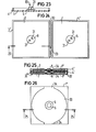
- FIGS. 23 and 24 finally show a further embodiment for a storage cassette or a pallet in which the bottom part 1 and the cover part 2 are firmly connected to one another in a hinge band 30 on one side.
- the pin arrangement 66 here consists of four pin-shaped partial elements 31 with a circular sector cross section, of which two mutually opposite partial elements are arranged on the raised support 5 of the base part 1 and the raised support 8 on the inside of the cover part 2.
- the partial elements 31 of the pin arrangement 66 arranged on the raised support 8 only engage in the center hole of the information carrier stored on the raised support 5 of the base part when the base part 1 and cover part 2 are folded together.
- the information carrier is fixed by clamping between the increased editions.
- base parts 1 and cover parts 2 When using separate base parts 1 and cover parts 2, as shown in FIGS. 25 and 26 in cross-section and in supervision, there is the possibility of designing base parts 1 as stackable and in this way already using them for the purpose of producing information carriers for transport purposes.
- the base parts 1 have for this purpose on the bottom side edge side approaches, which are offset by the width of the side wall 4 ' ⁇ from the edge inwards and engage in the respective underlying bottom part. These approaches 32 are of course designed so that they do not come into contact with the information carrier 7 stored in the bottom part arranged below.
- this base part 1 here practically consists of a plate in which a circular recess 33 is provided for receiving the information carrier 7.
- the recess 33 is interrupted at the edge only in the central area on both sides to create grip openings 34.
- grip openings recessed grips can also be provided in the area of two diagonally opposite corners.
- the base part 1 and the cover part 2, as well as the box-shaped container 23, can be produced in a conventional manner by means of pressing, injection molding, deep-drawing or foam molding of plastics. Cardboard-based production is also possible.
- the design of the base part and the cover part is expediently produced from a soft but inherently rigid molded foam, since here the pallet is inserted into the box-shaped container receives actual protection against damage.
Landscapes
- Engineering & Computer Science (AREA)
- Mechanical Engineering (AREA)
- Packaging For Recording Disks (AREA)
- Packaging Of Annular Or Rod-Shaped Articles, Wearing Apparel, Cassettes, Or The Like (AREA)
- Automatic Disk Changers (AREA)
- Automatic Tape Cassette Changers (AREA)
- Optical Record Carriers And Manufacture Thereof (AREA)
Abstract
Description
- Die Erfindung bezieht sich auf eine Aufbewahrungskassette, bestehend wenigstens aus einem flachen kastenförmigen Bodenteil und einem dieses Bodenteil an der Oberseite abschließenden abnehmbaren bzw. aufklappbaren Deckelteil.
- Solche, vorzugsweise zur Aufbewahrung normaler Schallplatten vorgesehenen Kassetten aus Karton oder Kunststoff sind im allgemeinen ungeeignet zur Aufbewahrung von plattenförmigen Informationsträgern hoher Speicherdichte, wie sie beispielsweise eine optisch auslesbare Videoplatte oder eine optisch auslesbare digitale Schallplatte darstellen. Zwar bietet eine solche Aulbewahrungskassette grundsätzlich einen gewissen Schutz gegen Beschädigung des Inhaltes, doch vermag hiermit ein ausreichender Schutz gegen Verzug aufgrund hoher Anforderungen an die Verzugsfreiheit nicht erfüllt zu werden. Abgesehen davon, daß der Informationsträger in der Kassette plan gelagert werden muß, muß auch dafür gesorgt werden, daß ein eventueller Verzug der Kassette sich nicht auf die in die Kassette eingelegte Platte überträgt.
- Es ist bereits vorgeschlagen (P 31 40 146.5) worden, zur Gewährleistung der zu fordernden Lagereigenschaften für solche plattenförmigen Informationsträger hoher Speicherdichte einen klappbaren Behälter nach Art eines Kassettenaufnahmebehälterns für eine Magnetbandkassette vorzusehen, in den der eigentliche Plattenbehälter einschiebbar ist.
- Der Erfindung liegt die Aufgabe zugrunde, für eine Aufbewahrungskassette der einleitend genannten Art eine weitere Lösung anzugeben, die es auch gestattet, den Informationsträger in Einfachbehältern zu lagern.
- Ausgehend von einer Aufbewahrungskassette,bestehend wenigstens aus einem flachen kastenförmigen Bodenteil und einem dieses Bodenteil an der Oberseite abschließenden, abnehmbaren bzw. aufklappbaren Deckelteil wird diese Aufgabe gemäß der Erfindung dadurch gelöst, daß zur Aufbewahrung von plattenförmigen Informationsträgern hoher Speicherdichte, insbesondere Digitalschallplatten, der Boden des Bodenteils für eine Lagerung des Informationsträgers ausschließlich im von Informationsspuren freien Mittenbereich eine gegenüber der eigentlichen Bodenfläche erhöhte Auflage mit einer zentralen, sich über die Auflagenoberseite erstreckenden Zapfenanordnung aufweist und daß die dem Mittellochdurchmesser des Informationsträgers angepaßte Zapfenanordnung im abgelegten Zustand des Informationsträgers in dessen Mittelloch eingreift.
- Der Erfindung liegt die wesentliche Erkenntnis zugrunde, daß eine optimale Sicherheit gegen Verzug eines Informationsträgers dadurch gegeben ist, daß er lediglich im informationsspurfreien Mittenbereich in der Aufbewahrungskassette gelagert wird, also der äußere Plattenbereich einschließlich des Bereiches, der die Informationsspurenspirale aufweist, frei schwebend ist.
- Zweckmäßig wird der Abstand des abgelegten Informationsträgers zum Kassettenboden und zum Kassettendeckel im Bereich außerhalb der Auflage so bemessen, daß eine Berührung des Informationsträgers mit dem Bodenteil und/ oder dem Deckelteil auch unter Berücksichtigung maximal zulässiger Verzugstoleranzen sowohl des Informationsträgers als auch des Kassettengehäuses mit Sicherheit vermieden ist.
- Die Fixierung des in die Kassette abgelegten Informationsträgers kann durch geeignete Gestaltung bzw. durch federnde Eigenschaften der Zapfenanordnung herbeigeführt werden. Zweckmäßige Ausgestaltungen hiervor sind in den Ansprüchen 4 bis 8 angegeben.
- Eine weitere vorteilhafte Möglichkeit der Fixierung des abgelegten Informationsträgers in der Kassette besteht darin, auf der Innenseite des Deckelteils eine weitere erhöhte Auflage vorzusehen, die so bemessen ist, daß der Informationsträger im geschlossenen Zustand der Kassette in seinem Mittelbereich zwischen beide Auflagen eingespannt ist. Zweckmäßige Ausgestaltungen hierfür sind in den Ansprüchen 9 und 10 angegeben.
- Die erhöhte Auflage im Bodenteil und gegebenenfalls auch im Deckelteil können auf verschiedene Weise gestaltet sein. Zweckmäßige Ausgestaltungen sind in den Ansprüchen 2 und 3 angegeben.
- Grundsätzlich können das Bodenteil und das Deckelteil voneinander getrennt sein. In diesem Falle sind lediglich für ihre gegenseitige Fixierung im zusammengefügten Zustand am Bodenteil und am Deckelteil einander zugeordnete randseitige Ausnehmungen und Ansätze vorzusehen. Für verschiedene Anwendungszwecke ist es jedoch sinnvoll, Boden- und Deckelteil einseitig über ein Scharnier fest miteinander zu verbinden.
- Zum leichteren Handhaben beim Einlegen und Herausnehmen des Informationsträgers aus der Kassette ist es sinnvoll, wenigstens im Bodenteil auf beiden Seiten im Mittenbereich Ausnehmungen zum Greifen des Informationsträgers vorzusehen.
- In Weiterbildung der Erfindung können für eine anspruchsvollere Verpackung das Bodenteil und das Deckelteil eine den Informationsträger in sich aufnehmende Palette darstellen, die gegebenenfalls zusammen mit einem Beiheft in einen kastenförmigen Behälter eingelegt oder . eingeschoben wird. Weitere vorteilhafte Ausgestaltungenfür eine solche Doppelbehälterkassette sind in den Ansprüchen 15 und 16 angegeben.
- In einer anderen Weiterbildung der Erfindung, bei der das Boden- und der Deckelteil voneinander trennbar und lediglich durch einander zugeordnete randseitige Ausnehmungen und Ansätze gegeneinander fixierbar sind, ist das Bodenteil mit dem darin abgelegten Informationsträger als stapelbare Palette gestaltet.
- Anhand von Ausführungsbeispielen soll die Erfindung im folgenden noch näher erläutert werden. In der Zeichnung bedeuten:
- Fig. 1 eine erste Ausführungsform einer Aufbewahrungskassette im Querschnitt,
- Fig. 2 eine zweite Ausführungsform einer Aufbewahrungskassette im Querschnitt,
- Fig. 3,4 eine erste Ausführungsform einer Zapfenanordnung im Querschnitt und in Aufsicht,
- Fig. 5,6 eine zweite Ausführungsform einer Zapfenanordnung im Querschnitt und in Aufsicht,
- Fig. 7,8 eine dritte Ausführungsform einer Zapfenanordnung im Querschnitt und in Aufsicht,
- Fig. 9,10 eine vierte Ausführungsform einer Zapfenanordnung im Querschnitt und in Aufsicht,
- Fig. 11 eine fünfte Ausführungsform einer Zapfenanordnung im Querschnitt mit deckelseitigem Spreizkonus,
- Fig. 12 der Mittelteil einer Aufbewahrungskassette im Querschnitt, bei dem der eingelegte Informationsträger zwischen deckel- und bodenseitiger erhöhter Auflage fixiert ist,
- Fig. 13 eine perspektivisch dargestellte Palettenausführung einer Aufbewahrungskassette für eine Fixierung des eingelegten Informationsträgers zwischen einer erhöhten boden- und deckelseitigen Auflage,
- Fig. 14 die Scharnierausführung der Aufbewahrungskassette nach Fig. 13,
- Fig. 15,16 die ausschnittsweise Darstellung von Fixiermöglichkeiten zwischen Bodenteil und Deckel bei getrennter Ausführung von Bodenteil und Deckelteil,
- Fig. 17 die perspektivische Darstellung einer Aufbewahrungskassette in Doppelbehälterausführung,
- Fig. 18 die perspektivische Darstellung einer Palette der Doppelbehälterausführung nach Fig. 17,
- Fig. 19 ein Ausschnitt einer Palette der Doppelbehälterausführung nach Fig. 17 mit Scharnieren,
- Fig. 20 eine Seitenansicht einer Palette der Doppelbehälterausführung nach Fig. 17 mit einem Beiblatt,
- Fig. 21 eine Seitenansicht einer weiteren Palette der Doppelbehälterausführung nach Fig. 17 mit Beiheft und Beiblattumhüllung,
- Fig. 22 eine Variante des kastenförmigen Behälters der Doppelbehälterausführung nach Fig. 17,
- Fig. 23,24 eine weitere Ausführung einer Aufbewahrungskassette, im Querschnitt und in Aufsicht,
- Fig. 25,26 eine weitere spezielle Ausführung eines stapelbaren Bodenteils für eine Aufbewahrungskassette im Querschnitt und in Aufsicht.
- Die im Schnitt dargestellte Aufbewahrungskassette nach Fig. 1 weist ein Bodenteil 1 auf, das an der Oberseite mit einem Deckelteil 2 zu einem geschlossenen Gehäuse ergänzt ist. Das Deckelteil 2 greift dabei mit seinem erhöhten Rand 3 über die Seitenwandung 4 des Bodenteils 1 über. Das Bodenteil 1 weist in seinem Mittenbereich eine erhöhte Auflage 5 kreisförmiger Gestalt auf, die wiederum in ihrer Mitte in einen Zapfen 6 übergeht. Auf dieser erhöhten Auflage 5 ist der eine digitale Schallplatte darstellende plattenförmige Informationsträger 7 abgelegt, in dessen Mittelloch der Zapfen 6 eingreift. Der kreisförmige Zapfen 6 ist hinsichtlich seines Durchmessers hier so bemessen, daß der Informationsträger 7 im auf die Auflage 5 aufgelegten Zustand leicht im Zapfen 6 verklemmt und damit in seiner Ablage fixiert ist. Die Auflagefläche der erhöhten Auflage 5 ist so bemessen, daß der plattenförmige Informationsträger lediglich mit seinem informationsspurfreien Mittenteil auf der erhöhten Auflage aufliegt. Eine sonstige Auflage ist nicht vorgesehen, so daß der Informationsträger in der Aufbewahrungskasstte über den Informationsspurbereich hinaus bis zum äußeren Rand auflagefrei ist. Die Abstände a und b des Informationsträgers 7 im auflagefreien Bereich zwischen dem Deckelteil 2 einerseits und dem Boden des Bodenteils 1 andererseits sind so gewählt, daß eine Berührung des Informationsträgers 7 in diesem auflagefreien Bereich mit dem Bodenteil und/oder dem Deckelteil auch unter Berücksichtigung maximal zulässiger Verzugstoleranzen sowohl des Informationsträgers als auch des Kassettengehäuses mit Sicherheit vermieden sind.
- Die Aufbewahrungskassette nach Fig. 2, ebenfalls im Schnitt dargestellt, zeigt eine Variante zur Ausführungsform nach Fig. 1 insofern, als hier die Fixierung des auf die erhöhte Auflage 5 des Bodenteils 1 abgelegten Informationsträgers 7 nicht im Zapfen 6 erfolgt. Das Fixieren geschieht hier dadurch, daß auf der Innenseite des Decketeils 2 eine weitere erhöhte Auflage 8 vorgesehen ist, die den Abmessungen der erhöhten Auflage 5 angepaßt ist und eine zentrale Aussparung 9 aufweist, in die im geschlossenen Zustand der Aufbewahrungskassette der Zapfen 6 eingreift. Mit anderen Worten wird hier der Informationsträger 7 zwischen die beiden erhöhten Auflagen 5 und 8 eingeklemmt.
- Im Unterschied zur Ausführungsform nach Fig. 1 sind das Bodenteil 1 und das Deckelteil 2 in Fig. 2 randseitig gleich ausgebildet und weisen jeweils einen umlaufenden erhöhten Rand 3' und 4' auf, die stirnseitig unmittelbar aneinander grenzen. Aufgrund der gleichartigen Ausführung der Profile des Bodenteils 1 und des Deckelteils 2 sind hier die Abstände a und b zwischen dem Informationsträger 7 im auflagefreien Bereich zwischen dem Deckelteil 2 einerseits und dem Bodenteil 1 andererseits gleich groß.
- Bei der in den Fig. 3 und 4 im Schnitt und in Aufsicht dargestellten Ausführungsform einer Zapfenanordnung besteht diese aus dem Zapfen 61 aus einem geeigneten elastischen Material. Der Zapfen 61 ist in das Bodenteil 1, und zwar in die erhöhte Auflage 5, eingelassen und weist zur Fixierung des Informationsträgers 7 auf der erhöhten Auflage 5 ein ringnasenförmiges Federrastprofil 10 auf. Oberhalb des Federrastprofils 10 mündet der Zapfen in einen Konus 11 aus. Das Federrastprofil 10 stellt eine Federrast dar, über die hinweg der abzulegende Informationsträger 7 in seine Sollstellung auf der erhöhten Auflage 5 einrastet.
- Eine weitere Ausführungsform für eine Zapfenanordnung im Querschnitt und in Aufsicht zeigen die Fig. 5 und 6. Die Zapfenanordnung besteht hier aus einem zum freien oberen Ende hin konisch auslaufenden Zapfen 62 mit einem senkrechten Schlitz 12, der einen in das Bodenteil 1 eingelassenen Federbügel 13 aufnimmt. Der Federbügel 13 ragt zu beiden Seiten des Zapfens 62 über dessen Umfangsfläche hinaus und bildet auf diese Weise die Federrast, über die hinweg der Informationsträger 7 auf der Auflage 5 fixiert wird.
- Bei der weiterhin im Querschnitt und in Aufsicht dargestellten Ausführung einer Zapfenanordnung nach den Fig. 7 und 8, bei der der Informationsträger 7 über einen Federeigenschaften aufweisenden Zapfen auf der Auflage 5 fixiert ist, besteht die Zapfenanordnung wiederum aus einem Zapfen 63, der ein tonnenförmiges Federrastprofil 10' hat und, wie die Aufsicht auf Fig. 8 zeigt, senkrecht zur Achse einen kreuzförmigen Querschnitt aufweist. Dieser kreuzförmige Querschnitt erhöht die Federeigenschaften des Materials und ermöglicht es, den Zapfen 63 unmittelbar bei der Herstellung des Bodenteils in einem Fertigungsvorgang mit diesem herzustellen.
- Eine Variante zur Ausführungsform nach den Fig. 7 Und 8 zeigen die Fig. 9 und 10 im Querschnitt und in Aufsicht. Die Zapfenanordnung 64 besteht hier aus mehreren Federsegmenten 14 nach Art einer axial geschlitzten Federhülse. Zum formschlüssigen Eingriff der Zapfenanordnung in das Mittelloch des Informationsträgers 7 weisen sie an ihrer Außenseite ein Federrastprofil 15 auf. Auch hier ist es möglich, das Bodenteil 1 gemeinsam mit der erhöhten Auflage 5 und der Zapfenanordnung 64 in einem Fertigungsvorgang herzustellen.
- Fig. 11 zeigt im Querschnitt eine weitere Möglichkeit für eine Fixierung des abzulegenden Informationsträgers auf der erhöhten Auflage 5 im Bodenteil 1 über die Zapfenanordnung hinweg auf. Die Zapfenanordnung 65 besteht hier aus einer Ringsegmentanordnung, deren zentrale Öffnung 16 unter die Auflagefläche der erhöhten Auflage 5 hinaus nach unten reicht. Das Verspannen der Ringstegsegmente gegen die Innenwandung des Mittelloches des auf die erhöhte Auflage 5 abgelegten Iniormationsträgers 7 erfolgt mittels eines auf der Innenseite des Deckelteils 2 vorgesehenen Spreizkonus 17, der in geschlossenem Zustand der Aufnahmekassette in die zentrale Öffnung der Ringsegmentanordnung eingreift.
- Bei den bisherigen Ausführungsbeispielen hatte die erhöhte Auflage im Bodenteil und gegebenenfalls auch die erhöhte Auflage im Deckelteil eine kreisscheibenförmige Gestalt. Dies ist jedoch nicht zwingend notwendig. Die erhöhte Auflage kann in jedem Fall auch ein auf eine Kreisfläche begrenztes Steg- bzw. Stiftmuster sein, was sich insbesondere da anbietet,.wo Materialeinsparungen erwünscht sind. Eine solche modifizierte Ausführungsform für eine erhöhte Auflage im Bodenteil 1 und eine solche im Deckelteil 2 entsprechend der im Zusammenhang mit Fig. 2 beschriebenen Ausführungsform zeigt Fig. 12. Die erhöhte Auflage 8' auf der Innenseite des Deckelteils 2 besteht hier lediglich aus einem Ringsteg. Die erhöhte Auflage 5' im Bodenteil 1 weist ihrerseits ein ringscheibenförmiges Mittelteil mit dem sich darüber erhebenden Zapfen 6 und einen hierzu konzentrisch angeordneten Ringsteg auf. Die Fixierung des Informationsträgers 7 erfolgt wie bei Fig. 2 durch Verspannen des Informationsträgers 7 zwischen der deckelseitigen und der bodenseitigen erhöhten Auflage 8' und 5'. Es versteht sich von selbst, daß eine materialsparende Gestaltung dieser erhöhten Auflagen im Deckelteil und im Bodenteil in gleicher Weise auch durch andere Ringsteg- oder Stiftmuster verwirklicht werden kann.
- Fig. 13 zeigt eine Palettenausführungsform einer Aufbewahrungskassette entsprechend Fig. 2 in perspektivischer Darstellung, bei der das Deckelteil 2 mit der erhöhten ringscheibenförmigen Auflage 8 und das Bodenteil 1 mit der scheibenförmigen erhöhten Auflage 5 und dem sich darüber erhebenden Zapfen 6 einseitig aneinanderhängend miteinander verbunden sind. Die einseitige Verbindung ist, wie in Fig. 13 angedeutet und in Fig. 14 ausschnittsweise dargestellt, im Übergangsbereich zwischen dem Bodenteil 1 und dem Decktelteil 2 als Scharnierband gestaltet. Das Scharnierband ist hier beispielsweise durch eine T-förmige Nut 18 verwirklicht. Weiterhin weisen sowohl das Bodenteil als auch das Deckelteil im Mittenbereich trapezförmige Aussparungen 19 auf, die das Einlegen und das Herausnehmen des Informationsträgers erleichtern. Gegebenenfalls kann auch auf die trapezförmigen Aussparungen 19 im Deckelteil verzichtet werden.
- Selbstverständlich können auch das Bodenteil 1 und das Deckelteil 2 völlig voneinander getrennt sein. In diesem Fall müssen jedoch Maßnahmen vorgesehen sein, um beim Verschließen der Aufbewahrungskassette eine gegenseitige Fixierung von Bodenteil und Deckelteil gewährleisten zu können. Die Fig. 15 zeigt ausschnittsweise eine Fixierung, bei der das Deckelteil 2 mit seinem äußeren Rand 3 über die nach innen gestufte Wandung 4 des Bodenteils 1, wie das auch bei der Ausführungsform nach Fig. 1 der Fall ist, übergreift. Bei der Ausführungsform entsprechend Fig. 2, bei der die Randteile an Boden- und Deckelteil plan aufeinanderliegen, können zur Fixierung, wie das beispielsweise Fig. 16 zeigt, in der Stirnfläche des Randes 4' des Bodenteils 1 kugelartige Ausnehmungen 20 vorgesehen sein, in die auf der Stirnseite 3' des Deckelteils 2 in entsprechender Anordnung angebrachte halbkugelförmige Ansätze 21 eingreifen.
- Die Paletten-Ausführungsform einer Aufbewahrungskassette nach Fig. 13 kann zur Gestaltung einer anspruchsvolleren Verpackung wie Fig. 17 zeigt umgeben von einem Beiblatt 22 in einen kastenförmigen Behälter 23 eingeschoben sein. Der kastenförmige Behälter 23 kann dabei auf allen Sieten beschriftet oder bedruckt sein. Er kann aber auch aus einem durchsichtigen Kunststoff bestehen, der lediglich im Bereich seiner Schmalseiten eine Beschriftung aufweist und im übrigen den Blick auf das bedruckte Beiblatt 22 freigibt. Für den Fall einer Beschriftung bzw. einer Bedruckung des kastenförmigen Behälters 23 kann auf ein bedrucktes Beiblatt auch verzichtet werden.
- Bei der Palette nach Fig. 18 sind das Bodenteil 1 und das Decktelteil 2 einseitig durch einen ein Scharnierband 25 darstellenden Klebestreifen aus Kunststofffolie oder Gewebe miteinander verbunden. Bei der in Fig. 19 ausschnittsweise gezeigten Variante erfolgt die klappbare einseitige Verbindung vom Bodenteil 1 und Deckelteil 2 mit Hilfe zweier Scharniere 24.
- Wie Fig. 17 noch zeigt, kann der kastenförmige Behälter 23 nach Fig. 17 an seinem hinteren Ende eine Aussparung 26 bzw. eine Bohrung 27 aufweisen, mit deren Hilfe es möglich ist, eine solche Zweibehälteranordnung in einem Verkaufsständer diebstahlssicher zu befestigen. Eine weitere Variante für eine solche Diebstahlsicherung im Zusammenhang mit einem kastenförmigen Behälter 23 zeigt Fig. 22, bei der dieser Behälter am einen Ende flanschartige gelochte Laschen 28 aufweist.
- Während bei der Ausführungsform nach Fig. 17 das Beiblatt 22 die Palette vollständig umschlingt und darüber hinaus auch noch einen Überschlag aufweist, ist entsprechend Fig. 20 ein Beiblatt 22' vorgesehen, das die Palette lediglich auf drei Seiten umgibt.
- Die Ausführung der Aufbewahrungskassette in Form einer Zweibehälteranordnung entsprechend Fig. 17 ist besonders dann sinnvoll, wenn der Informationsträger mit einem Beiheft versehen werden soll. Entsprechend der Ausführungsform nach Fig. 21 ist dieses Beiheft 29 der Palette beigelegt und die Palette und dieses Beiheft entsprechend der Ausführungsform nach Fig. 17 mit einem Beiblatt 22 umgeben. Das so gebildete Paket wird dann entsprechend Fig. 17 in den kastenförmigen Behälter 23 eingeschoben.
- Die Figuren 23 und 24 zeigen schließlich eine weitere Ausführungsform für eine Aufbewahrungskassette bzw. eine Palette, bei der das Bodenteil 1 und das Deckelteil 2 an einer Seite in einem Scharnierband 30 miteinander fest verbunden sind. Wie der Querschnitt des Bodenteils nach Fig. 23, aber auch die Aufsicht auf das Boden- und das Deckelteil nach Fig. 24 erkennen lassen, besteht hier die Zapfenanordnung 66 aus vier stiftförmigen Teilelementen 31 mit kreissektorförmigem Querschnitt, von denen jeweils zwei einander gegenüberliegende Teilelemente auf der erhöhten Auflage 5 des Bodenteils 1 und der erhöhten Auflage 8 auf der Innenseite des Deckelteils 2 angeordnet sind. Hier greifen sozusagen die auf der erhöhten Auflage 8 angeordneten Teilemente 31 der Zapfenanordnung 66 erst beim Zusammenklappen von Bodenteil 1 und Deckelteil 2 in das Mittelloch des auf die erhöhte Auflage 5 des Bodenteils abgelegten Informationsträgers ein. Gleichzeitig wird der Informationsträger hierbei durch Einspannen zwischen den erhöhten Auflagen fixiert.
- Bei Verwendung von getrennten Bodenteilen 1 und Deckelteilen 2 besteht, wie die Fig. 25 und 26 im Querschnitt und in Aufsicht zeigen, die Möglichkeit, Bodenteile 1 stapelbar auszuführen und sie auf diese Weise bereits im Rahmen der Informationsträgerherstellung für Transportzwecke zu verwenden. Die Bodenteile 1 weisen hierzu auf der Bodenseite randseitige Ansätze auf, die um die Breite der Seitenwandung 4' \ vom Rand nach innen versetzt sind und in das jeweils darunterliegende Bodenteil eingreifen. Diese Ansätze 32 sind selbstverständlich so ausgeführt, daß sie hierbei nicht in Berührung mit den in dem darunter angeordneten Bodenteil abgelegten Informationsträger 7 kommen.
- Wie die Aufsicht für ein solches stapelbares Palettenbodenteil erkennen läßt, besteht dieses Bodenteil 1 hier praktisch aus einer Platte, in der eine kreisförmige Ausnehmung 33 für die Aufnahme des Informationsträgers 7 vorgesehen ist. Die Ausnehmung 33 wird randseitig lediglich im Mittenbereich auf beiden Seiten zur Schaffung von Grifföffnungen 34 unterbrochen. Anstelle von Grifföffnungen können im Bereich zweier einander diagonal gegenüber liegender Ecken auch Griffmulden vorgesehen sein.
- Das Bodenteil 1 und das Deckelteil 2, wie auch der kastenförmige Behälter 23 können in üblicher Weise mittels Pressen, Spritzen, Tiefziehen oder Formschäumen von Kunststoffen hergestellt werden. Auch eine Herstellung auf Kartonbasis ist möglich. Bei einer Zweibehälterausführungsform, also bei der das Bodenteil und das Deckelteil die Funktion einer Palette haben, wird die Ausführung des Bodenteils und des Deckelteils zweckmäßig aus einem weichen jedoch in sich starren Formschaum hergestellt, da hier die Palette ja durch ihre Einbringung in den kastenförmigen Behälter den eigentlichen Schutz gegen Beschädigung erhält.
Claims (17)
Applications Claiming Priority (2)
| Application Number | Priority Date | Filing Date | Title |
|---|---|---|---|
| DE3205478 | 1982-02-16 | ||
| DE19823205478 DE3205478A1 (de) | 1982-02-16 | 1982-02-16 | Aufbewahrungskassette fuer plattenfoermige informationstraeger hoher speicherdichte |
Publications (2)
| Publication Number | Publication Date |
|---|---|
| EP0086484A1 true EP0086484A1 (de) | 1983-08-24 |
| EP0086484B1 EP0086484B1 (de) | 1987-06-03 |
Family
ID=6155848
Family Applications (1)
| Application Number | Title | Priority Date | Filing Date |
|---|---|---|---|
| EP83101404A Expired EP0086484B1 (de) | 1982-02-16 | 1983-02-14 | Aufbewahrungskassette für plattenförmige Informationsträger hoher Speicherdichte |
Country Status (9)
| Country | Link |
|---|---|
| US (1) | US4874085A (de) |
| EP (1) | EP0086484B1 (de) |
| JP (2) | JPH0651506B2 (de) |
| AT (1) | ATE27664T1 (de) |
| CA (1) | CA1198208A (de) |
| DE (2) | DE3205478A1 (de) |
| ES (4) | ES278032Y (de) |
| HK (1) | HK99192A (de) |
| MX (1) | MX155438A (de) |
Cited By (15)
| Publication number | Priority date | Publication date | Assignee | Title |
|---|---|---|---|---|
| EP0198083A4 (de) * | 1984-09-29 | 1987-06-29 | Sony Corp | Plattenschutzabdeckung in Verbindung mit einer Platte. |
| EP0269159A1 (de) * | 1986-11-05 | 1988-06-01 | Koninklijke Philips Electronics N.V. | Gehäuse für optisch lesbare Platte |
| EP0212377A3 (de) * | 1985-08-12 | 1988-09-14 | Siemens Aktiengesellschaft | Cassette für eine Compactdisc aus Kunststoff |
| EP0344829A3 (de) * | 1988-05-04 | 1989-12-20 | Dielco Plastic Industrie B.V. | Gehäuse für plattenförmige Aufzeichnungsträger |
| EP0302549A3 (de) * | 1987-08-03 | 1990-03-07 | Philips and Du Pont Optical Deutschland GmbH | Aufbewahrungskassette für einen plattenförmigen Informationsträger |
| EP0414306A1 (de) * | 1989-08-19 | 1991-02-27 | Philips and Du Pont Optical Company | Kassette zum Aufbewahren von Platten mit Mittelöffnung |
| WO1992015505A1 (en) * | 1991-03-08 | 1992-09-17 | Martin Corneliussen | Container or package for compact discs, video cassettes, tools or the like |
| WO1992022066A1 (de) * | 1991-06-07 | 1992-12-10 | Pilz Technologie Gmbh | Behälter (cd-box) für cd-platten (digitalschallplatten) und ähnliche plattenförmige informationsträger |
| EP0559273A3 (en) * | 1992-03-02 | 1993-11-18 | Philips Nv | Package for a disc-shaped record carrier having a centre hole |
| US5284248A (en) * | 1988-08-29 | 1994-02-08 | Cartonneries De Thulin, S.A. | Storage case and a disc holding part for storage cases for round data discs |
| EP1126465A3 (de) * | 2000-01-24 | 2001-08-29 | Sergio Tomasoni | Behälter für plattenförmige Gegenstände, insbesondere Compactdiscs |
| WO2004097833A1 (en) * | 2003-04-30 | 2004-11-11 | Zeljko Zajec | One-part case for digital records' carriers with possibility of connexion with cases of the same type |
| WO2007033682A3 (en) * | 2005-09-22 | 2007-06-28 | Scanavo As | Media disc storage container |
| CN101301752B (zh) * | 2007-05-11 | 2011-05-25 | 株式会社迪思科 | 刀具盒及刀具盒的使用方法 |
| KR20120095948A (ko) * | 2009-11-10 | 2012-08-29 | 페더럴-모걸 코오포레이숀 | 블로바이 특징을 갖는 피스톤 및 내연기관의 돌발적 고장을 방지하는 방법 |
Families Citing this family (110)
| Publication number | Priority date | Publication date | Assignee | Title |
|---|---|---|---|---|
| DE3425579A1 (de) * | 1984-07-11 | 1986-01-16 | Polygram Gmbh, 2000 Hamburg | Aufbewahrungskassette fuer plattenfoermige informationstraeger hoher speicherdichte |
| JPS61132557U (de) * | 1985-02-01 | 1986-08-19 | ||
| DE3512477C2 (de) * | 1985-04-09 | 1995-02-09 | Nikkodo Co | Gehäuse für eine Compact Disc |
| JPS6280895U (de) * | 1985-11-11 | 1987-05-23 | ||
| US4709812A (en) * | 1986-07-11 | 1987-12-01 | Agi Incorporated | Compact disc package and a method of making same |
| US4903829A (en) * | 1988-10-07 | 1990-02-27 | Clemens Philip M | Container for compact disc |
| JPH0269889U (de) * | 1988-11-14 | 1990-05-28 | ||
| DE8900764U1 (de) * | 1989-01-25 | 1989-03-16 | Basf Ag, 6700 Ludwigshafen | Verpackungsbehälter für eine Mehrzahl von in Kreisform befindlichen Aufzeichnungsträgern |
| DE3932425A1 (de) * | 1989-09-28 | 1991-04-11 | Philips & Du Pont Optical | Verpackung fuer wenigstens eine mit einem zentralen mittelloch versehene platte |
| WO1992006904A1 (en) * | 1990-10-22 | 1992-04-30 | Hansen Darrell L | Optical storage disc protector |
| US5219417A (en) * | 1991-05-10 | 1993-06-15 | Ivy Hill Corporation | Compact disc storage package |
| AU662745B2 (en) * | 1991-07-31 | 1995-09-14 | Sony Corporation | Disc cartridge |
| JP3513766B2 (ja) * | 1991-09-04 | 2004-03-31 | 株式会社ソニー・ミュージックエンタテインメント | ディスクカートリッジの収納ケース |
| US5253751A (en) * | 1991-10-23 | 1993-10-19 | Sony Music Entertainment Inc. | Packaging for compact discs |
| USD335215S (en) | 1992-01-06 | 1993-05-04 | Atlanta Precision Molding Co. | Storage container for disk-shaped object |
| US5238107A (en) * | 1992-01-07 | 1993-08-24 | Kownacki Charles D | Disc storage container having a securing means central aperture |
| US5236081A (en) * | 1992-01-31 | 1993-08-17 | Shape Inc. | Compact disc package |
| US5261534A (en) * | 1992-02-04 | 1993-11-16 | Laserkrib, Inc. | Container for multiple laser disks |
| US5815344A (en) * | 1992-02-17 | 1998-09-29 | Sony Corporation | Disc cartridge loading apparatus |
| US5310053A (en) * | 1992-03-20 | 1994-05-10 | Shape Inc. | Telescoping compact disc holder and foldable cover |
| US5267647A (en) * | 1992-04-16 | 1993-12-07 | Sony Corporation | Storage container for mini-disk cartridges |
| US5310054A (en) * | 1992-04-16 | 1994-05-10 | Sony Corporation | Storage container for disk-shaped object |
| US5495940A (en) * | 1992-04-16 | 1996-03-05 | Sony Corporation | Storage container for mini-disk cartridges |
| USD352199S (en) | 1992-05-26 | 1994-11-08 | Sony Corporation | Storage container for a mini-optical disc cartridge |
| US5377827A (en) * | 1992-06-22 | 1995-01-03 | Queens Group, Inc. | Media disk storage container with printed paperboard sheets |
| USD342379S (en) | 1992-07-08 | 1993-12-21 | Yoshihiko Taniyama | Storage container for a miniature disk cartridge |
| US5246107A (en) * | 1992-08-20 | 1993-09-21 | Creative Point, Inc. | Wallet style compact disc storage unit |
| DE4228343A1 (de) * | 1992-08-26 | 1994-03-10 | Winkler Duennebier Kg Masch | Schutzhülle für einen scheibenförmigen Informationsträger |
| JP3201006B2 (ja) * | 1992-09-04 | 2001-08-20 | ソニー株式会社 | ディスクカートリッジの収納ケース |
| US5344039A (en) * | 1992-09-08 | 1994-09-06 | Yoshihiko Taniyama | Storage container |
| US5289616A (en) * | 1992-09-08 | 1994-03-01 | Yoshihiko Taniyama | Hinge with motion limiting mechanism |
| DE9212275U1 (de) * | 1992-09-11 | 1993-02-11 | BASF Magnetics GmbH, 6800 Mannheim | Spulenbehälter für Magnetbänder |
| WO1994014161A1 (en) * | 1992-12-08 | 1994-06-23 | Doukas Robert Fonias | Protective covers for optical discs |
| USD347728S (en) | 1992-12-14 | 1994-06-14 | Yoshihiko Taniyama | Storage container |
| US5377825A (en) * | 1993-01-04 | 1995-01-03 | Sykes; Philip K. | Compact disc storage case |
| USD358079S (en) | 1993-03-11 | 1995-05-09 | Yoshihiko Taniyama | Divider for a double disc cover |
| US5285893A (en) * | 1993-05-14 | 1994-02-15 | Digital Audio Disc Corporation | Storage case for multiple compact discs and related printed material |
| US5332089A (en) * | 1993-06-23 | 1994-07-26 | Ivy Hill Corporation | Storage package for recording medium |
| US5417324A (en) * | 1994-04-08 | 1995-05-23 | Joyce Development Corporation | Clear molded thermoplastic compact disc supporting tray |
| US5515968A (en) * | 1994-06-13 | 1996-05-14 | Taniyama; Yoshihiko | Storage container having an improved hub for gripping an optical disk |
| AT294U1 (de) * | 1994-06-16 | 1995-07-25 | Oesterreichische Blechwarenfab | Verpackung fuer speicherplatten, insbesondere compact-discs |
| US5551560A (en) * | 1994-06-30 | 1996-09-03 | Alpha Enterprises, Inc. | Container for compact disc and jewel box |
| US5494156A (en) * | 1994-07-21 | 1996-02-27 | Optima Precision Inc. | Disc retainer for disc storage device |
| DE9415985U1 (de) * | 1994-10-05 | 1994-12-01 | Gruss Metallverpackungen GmbH & Co., 40721 Hilden | Verpackungsbehälter für Compact Discs |
| USD393394S (en) | 1994-10-11 | 1998-04-14 | Queens Group, Inc. | Media disk storage package |
| DE19503264C2 (de) * | 1995-02-02 | 2000-10-05 | Luckow Hans Juergen | Halterung für Compact Discs |
| US5513749A (en) * | 1995-05-11 | 1996-05-07 | Simmons; Charles B. | Storage case for multiple compact discs |
| US5593030A (en) * | 1995-05-19 | 1997-01-14 | Tell; Richard B. | Compact disc holder |
| DE19518822C1 (de) * | 1995-05-23 | 1996-06-05 | Rasselstein Ag | Blechbehälter für eine CD-Platte o. dgl. |
| USD395190S (en) | 1995-07-20 | 1998-06-16 | Queens Group, Inc. | Digital video disk storage package |
| USD412261S (en) * | 1995-07-20 | 1999-07-27 | Q2 Marketing, Llc | Video disk storage package |
| US5697496A (en) * | 1995-10-20 | 1997-12-16 | Mcqueen, Inc. | Package for compact disks or computer diskettes |
| US5887713A (en) * | 1995-10-26 | 1999-03-30 | Ultrapac, Inc. | Holder for compact discs |
| AU2289697A (en) * | 1996-03-22 | 1997-10-17 | Edgar Bos | Carrier consisting of a biodegradable material for a disc-shaped data carrier |
| US5685424A (en) * | 1996-04-17 | 1997-11-11 | Rose City Paper Box, Inc. | Protective retainer for a compact disc |
| DE19615790A1 (de) * | 1996-04-20 | 1997-10-23 | Walter Schlutius | Vorrichtung zur Befestigung einer mit einem Durchbruch versehenen Datenträgerplatte |
| CA2253286A1 (en) | 1996-04-30 | 1997-11-06 | Peter Antony Farrar | Apparatus for holding a compact disk |
| US5788069A (en) * | 1996-06-27 | 1998-08-04 | Westvaco Corporation | CD holder with spring |
| JPH1050023A (ja) * | 1996-07-30 | 1998-02-20 | Mitsubishi Chem Corp | 記録媒体用カートリッジ |
| US5975291A (en) * | 1996-10-24 | 1999-11-02 | Shanas Attar | Apparatus for holding an article |
| US5779040A (en) * | 1996-10-24 | 1998-07-14 | Shanas Attar | Apparatus for holding an article |
| US5975298A (en) | 1997-01-02 | 1999-11-02 | Alpha Enterprises, Inc. | Video cassette container |
| US5845771A (en) * | 1997-05-23 | 1998-12-08 | Fu; Hsin-Yu | Case for compact disks |
| US6000537A (en) * | 1997-06-10 | 1999-12-14 | U.S. Philips Corporation | Housing with readable side walls for a disc-shaped information carrier |
| US5819926A (en) * | 1997-07-23 | 1998-10-13 | Ivy Hill Corporation | Package for a recording medium and method of assembling same |
| DE19732596C2 (de) * | 1997-07-29 | 1999-05-27 | Staehle Gmbh Blechpackungen | Blechbehälter für eine CD-Platte |
| GB2331981B (en) * | 1997-12-05 | 2001-06-20 | Dubois Ltd | Enclosure holding data carrier |
| JPH11213628A (ja) * | 1998-01-21 | 1999-08-06 | Toshiba Corp | 記録媒体とその再生装置および記録再生装置 |
| US6065594A (en) * | 1998-04-01 | 2000-05-23 | Alpha Enterprises, Inc. | Storage container for recorded media |
| US5996788A (en) * | 1998-04-01 | 1999-12-07 | Alpha Enterprises, Inc. | Storage container for recorded media |
| USD439435S1 (en) | 1998-07-01 | 2001-03-27 | Alpha Enterprises, Inc. | Hub for holding recorded media |
| DE19840391A1 (de) * | 1998-09-04 | 2000-03-09 | Sonopress Prod | Kassette zur Aufnahme eines Informationsträgers sowie Verfahren und Einrichtung zum Bedrucken derselben |
| US6216857B1 (en) * | 1998-09-25 | 2001-04-17 | Alexandra Gordon | Packaging device for disc-shaped items and related materials and method for packaging such disks and material |
| US6093140A (en) * | 1998-11-23 | 2000-07-25 | Sagoma Plastics | Media storing tray-board mechanical attachment |
| US6276523B2 (en) | 1998-12-17 | 2001-08-21 | Jacaranda A. Sanders | Compact disc container |
| US6016909A (en) * | 1999-02-01 | 2000-01-25 | Chang; Kun-Fa | Compact disk receiving device |
| DE19909475C2 (de) * | 1999-03-04 | 2001-08-23 | Bayerische Motoren Werke Ag | Aufbewahrungsbehälter für eine CD oder dergleichen |
| USD430424S (en) * | 1999-03-05 | 2000-09-05 | Alpha Enterpriss, Inc. | Tray for holding recorded media |
| USD426978S (en) * | 1999-03-05 | 2000-06-27 | Alpha Enterprises, Inc. | Hub for holding recorded media |
| USD426721S (en) * | 1999-03-05 | 2000-06-20 | Alpha Enterprises, Inc. | Tray for holding recorded media |
| DE20004218U1 (de) * | 1999-03-09 | 2000-07-27 | Chin Ta Industrial Co., Ltd., Taipeh/T'ai-pei | Vorrichtung zum Aufbewahren von CD's |
| JP2001002173A (ja) | 1999-06-25 | 2001-01-09 | Tdk Corp | ディスク収納ケース及びディスクトレイ |
| DE19963958C2 (de) * | 1999-12-31 | 2003-04-17 | Dirk Andreas | Behälter |
| FR2805383A1 (fr) * | 2000-02-17 | 2001-08-24 | Achat Et Distrib D Articles De | Support de rangement d'au moins un objet en forme de disque |
| US6698586B2 (en) | 2000-07-14 | 2004-03-02 | Nexpak Corporation | Storage container for disc-shaped items of recorded media |
| GB0024496D0 (en) * | 2000-10-05 | 2000-11-22 | Pettigrew Michael | New compact disc case |
| US6516945B2 (en) | 2001-01-24 | 2003-02-11 | Nexpak Corporation | Device for locking a media disc to a retaining hub |
| WO2002066342A1 (en) | 2001-02-20 | 2002-08-29 | Nexpak Corporation | Storage container for recorded media |
| HK1041776A2 (en) * | 2001-04-24 | 2002-07-12 | Sang Simon Chan Chak | A holder for an optically readable information disc |
| US6651811B2 (en) | 2001-05-24 | 2003-11-25 | Concord Continental Ltd. | Anti-pilferage device for optical disc holder |
| DE10129150C1 (de) * | 2001-06-16 | 2002-11-21 | Rene Friedrich | Anordnung zum Sichern eines scheibenförmigen Informationsträgers mit Mittelloch gegen unbemerkte Entnahme aus einer Aufbewahrungsbox |
| US7269124B2 (en) * | 2001-07-20 | 2007-09-11 | Thomas Paul Downs | Protective divider and enclosure disc assembly for laser discs and laser disc drives |
| US7051871B2 (en) | 2001-10-16 | 2006-05-30 | Loritz & Associates, D.B.A. L&A Plastic Molding & Tooling | Optical disk containers |
| US20030019772A1 (en) * | 2002-05-03 | 2003-01-30 | Chan Vincent Tak Wing | Apparatus for holding a media storage disk having a resilient hub |
| US6899223B2 (en) | 2002-05-09 | 2005-05-31 | Bert-Co Industries, Inc. | Form for a package and method of making same |
| JP2004079014A (ja) * | 2002-08-09 | 2004-03-11 | Toshiba Corp | ディスクカートリッジ |
| US6802419B2 (en) | 2002-10-11 | 2004-10-12 | Bert Co Industries, Inc. | Package form and method of making a package |
| US6729469B1 (en) | 2002-10-28 | 2004-05-04 | Technicolor Videocassette, Inc. | Storage holder for a compact disc |
| US7124885B1 (en) | 2002-11-27 | 2006-10-24 | Weingarden Marshall L | Hub posts for mounting information-bearing disks |
| US6886689B2 (en) * | 2003-03-06 | 2005-05-03 | Magnetix Corporation | Apparatus for containing and displaying objects |
| JP4021415B2 (ja) * | 2003-06-20 | 2007-12-12 | 株式会社日本ビデオセンター | 保持手段の妄動防止機能を備えた円盤状記録媒体のケース |
| NL1023834C2 (nl) * | 2003-07-07 | 2005-01-10 | Fountain Tech Bv | Inrichting voor het verpakken van plaatvormige informatiedragers. |
| EP1647025B1 (de) * | 2003-07-14 | 2007-03-07 | Koninklijke Philips Electronics N.V. | Gehäuse zur aufnahme von mehreren informationsplatten |
| CA2548581C (en) * | 2003-12-10 | 2013-03-19 | Nexpak Corporation | Storage container with locking device for recorded media |
| US7708139B2 (en) * | 2004-03-05 | 2010-05-04 | Meadwestvaco Corporation | Recording medium storage package having improved rosette |
| DE102005007116B3 (de) * | 2005-02-16 | 2006-07-06 | Gerhard Conze Kg | Speicherschale für flächigen Gegenstand |
| FI20050541L (fi) * | 2005-05-23 | 2006-11-24 | Prevex Ab Oy | CD-rasia vaihtelevalle määrälle CD-levyjä |
| US8201425B2 (en) | 2005-06-08 | 2012-06-19 | Autronic Plastics, Inc. | Hub lock for media disc storage container |
| WO2007075117A1 (fr) * | 2005-12-28 | 2007-07-05 | Kruchinin Aleksandr Konstantin | Box pour supports optiques |
| WO2008068282A1 (fr) * | 2006-12-07 | 2008-06-12 | Montres Breguet Sa | Boîte protectrice pour le transport ou le stockage d'une pièce ayant la forme d'une plaque percée d'une ouverture |
Citations (6)
| Publication number | Priority date | Publication date | Assignee | Title |
|---|---|---|---|---|
| US3109539A (en) * | 1960-11-17 | 1963-11-05 | Walfredo Toscanni | Record album |
| US3949872A (en) * | 1973-07-19 | 1976-04-13 | Francis Paudras | Individual case for phonograph records |
| FR2337397A1 (fr) * | 1976-01-02 | 1977-07-29 | Thomson Brandt | Dispositif d'entrainement d'un videodisque a stabilisation aerodynamique |
| US4068851A (en) * | 1976-01-23 | 1978-01-17 | Victor Company Of Japan, Limited | Audio/video disc playback apparatus with means for correctly positioning the disc relative to a reference level |
| US4084540A (en) * | 1977-05-19 | 1978-04-18 | Discwasher, Inc. | Apparatus for applying lubricating and protective film to phonograph records |
| EP0032771A1 (de) * | 1980-01-22 | 1981-07-29 | Koninklijke Philips Electronics N.V. | Signalaufzeichnungs- und/oder Wiedergabesystem |
Family Cites Families (20)
| Publication number | Priority date | Publication date | Assignee | Title |
|---|---|---|---|---|
| DE7416151U (de) * | 1974-10-03 | Crested Butte Records Inc | Vorrichtung zum Schutz von Schallplatten und dergleichen | |
| US1255690A (en) * | 1917-03-16 | 1918-02-05 | John B Barlow | Holder for phonograph-records. |
| GB427141A (en) * | 1934-03-19 | 1935-04-16 | Alfred Trafford | Improvements relating to license holders for use on motor vehicles |
| US3049872A (en) * | 1958-10-30 | 1962-08-21 | Phillips Petroleum Co | Jet engine combustion process |
| DE1190865B (de) * | 1963-06-15 | 1965-04-08 | Wilhelm Lepper Dr Ing | Verschluss an flachen Huellen, Taschen u. dgl., insbesondere fuer Schallplatten |
| US3381916A (en) * | 1966-06-29 | 1968-05-07 | Porter Co Inc H K | Tape rule case and brake construction |
| FR1524122A (fr) * | 1967-01-27 | 1968-05-10 | Boîtier protecteur individuel pour disques microsillons | |
| US3530981A (en) * | 1968-12-26 | 1970-09-29 | Phillips Petroleum Co | Record mailer |
| US3825112A (en) * | 1972-10-30 | 1974-07-23 | Crested Butte Records Inc | Record cover |
| US3907193A (en) * | 1974-04-08 | 1975-09-23 | Autoplex Corp | Plastic folding containers and process and apparatus for making same |
| US3951264A (en) * | 1974-10-29 | 1976-04-20 | Dynastor, Inc. | Flexible disc cartridge |
| US3904033A (en) * | 1974-11-08 | 1975-09-09 | Xomox Corp | Pick-guard |
| US4049119A (en) * | 1976-05-17 | 1977-09-20 | National Blank Book Company, Inc. | Tape cassette filing unit |
| DE2649346A1 (de) * | 1976-10-29 | 1978-05-03 | Alm Stefan | Kassette fuer schallplatten |
| US4231474A (en) * | 1978-04-07 | 1980-11-04 | Sony Corporation | Storage case |
| DE2816045C2 (de) * | 1978-04-13 | 1980-07-03 | Gregor Hofbauer - Gmbh & Co, 8000 Muenchen | Zweischaliger Behälter, insbesondere Koffer |
| US4235334A (en) * | 1979-01-12 | 1980-11-25 | Ahn Chul S | Cassette storage case |
| JPS5853750Y2 (ja) * | 1979-07-07 | 1983-12-06 | 日本ビクター株式会社 | 情報記録盤収納具 |
| DE3027804A1 (de) * | 1980-07-23 | 1982-02-18 | Hoechst Ag, 6000 Frankfurt | Verpackung, insbes. fuer plattenfoermige gegenstaende |
| US4499996A (en) * | 1983-12-29 | 1985-02-19 | Rca Corporation | Protective cartridge for disc record |
-
1982
- 1982-02-16 DE DE19823205478 patent/DE3205478A1/de not_active Withdrawn
-
1983
- 1983-02-14 DE DE8383101404T patent/DE3371954D1/de not_active Expired
- 1983-02-14 EP EP83101404A patent/EP0086484B1/de not_active Expired
- 1983-02-14 AT AT83101404T patent/ATE27664T1/de not_active IP Right Cessation
- 1983-02-15 CA CA000421600A patent/CA1198208A/en not_active Expired
- 1983-02-16 ES ES1983278032U patent/ES278032Y/es not_active Expired
- 1983-02-16 JP JP58022966A patent/JPH0651506B2/ja not_active Expired - Lifetime
-
1984
- 1984-07-16 ES ES1984280546U patent/ES280546Y/es not_active Expired
- 1984-07-16 ES ES1984280548U patent/ES280548Y/es not_active Expired
- 1984-07-16 ES ES1984280547U patent/ES280547Y/es not_active Expired
-
1988
- 1988-02-15 MX MX889576A patent/MX155438A/es unknown
- 1988-10-18 US US07/259,554 patent/US4874085A/en not_active Expired - Lifetime
-
1991
- 1991-07-09 JP JP3167895A patent/JPH05250836A/ja active Pending
-
1992
- 1992-12-10 HK HK991/92A patent/HK99192A/xx not_active IP Right Cessation
Patent Citations (6)
| Publication number | Priority date | Publication date | Assignee | Title |
|---|---|---|---|---|
| US3109539A (en) * | 1960-11-17 | 1963-11-05 | Walfredo Toscanni | Record album |
| US3949872A (en) * | 1973-07-19 | 1976-04-13 | Francis Paudras | Individual case for phonograph records |
| FR2337397A1 (fr) * | 1976-01-02 | 1977-07-29 | Thomson Brandt | Dispositif d'entrainement d'un videodisque a stabilisation aerodynamique |
| US4068851A (en) * | 1976-01-23 | 1978-01-17 | Victor Company Of Japan, Limited | Audio/video disc playback apparatus with means for correctly positioning the disc relative to a reference level |
| US4084540A (en) * | 1977-05-19 | 1978-04-18 | Discwasher, Inc. | Apparatus for applying lubricating and protective film to phonograph records |
| EP0032771A1 (de) * | 1980-01-22 | 1981-07-29 | Koninklijke Philips Electronics N.V. | Signalaufzeichnungs- und/oder Wiedergabesystem |
Non-Patent Citations (1)
| Title |
|---|
| IBM TECHNICAL DISCLOSURE BULLETIN, Band 20, Nr. 6, November 1977, Seiten 2376-2377, New York, USA * |
Cited By (18)
| Publication number | Priority date | Publication date | Assignee | Title |
|---|---|---|---|---|
| EP0198083A4 (de) * | 1984-09-29 | 1987-06-29 | Sony Corp | Plattenschutzabdeckung in Verbindung mit einer Platte. |
| EP0212377A3 (de) * | 1985-08-12 | 1988-09-14 | Siemens Aktiengesellschaft | Cassette für eine Compactdisc aus Kunststoff |
| EP0269159A1 (de) * | 1986-11-05 | 1988-06-01 | Koninklijke Philips Electronics N.V. | Gehäuse für optisch lesbare Platte |
| EP0302549A3 (de) * | 1987-08-03 | 1990-03-07 | Philips and Du Pont Optical Deutschland GmbH | Aufbewahrungskassette für einen plattenförmigen Informationsträger |
| EP0344829A3 (de) * | 1988-05-04 | 1989-12-20 | Dielco Plastic Industrie B.V. | Gehäuse für plattenförmige Aufzeichnungsträger |
| US5284248A (en) * | 1988-08-29 | 1994-02-08 | Cartonneries De Thulin, S.A. | Storage case and a disc holding part for storage cases for round data discs |
| EP0414306A1 (de) * | 1989-08-19 | 1991-02-27 | Philips and Du Pont Optical Company | Kassette zum Aufbewahren von Platten mit Mittelöffnung |
| WO1992015505A1 (en) * | 1991-03-08 | 1992-09-17 | Martin Corneliussen | Container or package for compact discs, video cassettes, tools or the like |
| FR2677480A1 (fr) * | 1991-06-07 | 1992-12-11 | Pilz Technologie Gmbh | Boitier pour disques compacts (disques audionumeriques) et supports d'informations similaires en forme de plaque. |
| WO1992022066A1 (de) * | 1991-06-07 | 1992-12-10 | Pilz Technologie Gmbh | Behälter (cd-box) für cd-platten (digitalschallplatten) und ähnliche plattenförmige informationsträger |
| EP0559273A3 (en) * | 1992-03-02 | 1993-11-18 | Philips Nv | Package for a disc-shaped record carrier having a centre hole |
| EP1126465A3 (de) * | 2000-01-24 | 2001-08-29 | Sergio Tomasoni | Behälter für plattenförmige Gegenstände, insbesondere Compactdiscs |
| WO2004097833A1 (en) * | 2003-04-30 | 2004-11-11 | Zeljko Zajec | One-part case for digital records' carriers with possibility of connexion with cases of the same type |
| US7520384B2 (en) | 2003-04-30 | 2009-04-21 | Zeljko Zajec | One piece connectable case for optical media |
| WO2007033682A3 (en) * | 2005-09-22 | 2007-06-28 | Scanavo As | Media disc storage container |
| CN101301752B (zh) * | 2007-05-11 | 2011-05-25 | 株式会社迪思科 | 刀具盒及刀具盒的使用方法 |
| KR20120095948A (ko) * | 2009-11-10 | 2012-08-29 | 페더럴-모걸 코오포레이숀 | 블로바이 특징을 갖는 피스톤 및 내연기관의 돌발적 고장을 방지하는 방법 |
| KR101686873B1 (ko) | 2009-11-10 | 2016-12-15 | 페더럴-모걸 코오포레이숀 | 블로바이 특징을 갖는 피스톤 및 내연기관의 돌발적 고장을 방지하는 방법 |
Also Published As
| Publication number | Publication date |
|---|---|
| ES280547Y (es) | 1985-08-01 |
| ATE27664T1 (de) | 1987-06-15 |
| DE3371954D1 (en) | 1987-07-09 |
| ES280548U (es) | 1985-02-16 |
| JPS58155583A (ja) | 1983-09-16 |
| ES280546U (es) | 1985-02-01 |
| CA1198208A (en) | 1985-12-17 |
| ES278032U (es) | 1985-02-01 |
| JPH0651506B2 (ja) | 1994-07-06 |
| ES280548Y (es) | 1985-09-01 |
| ES280546Y (es) | 1985-12-01 |
| DE3205478A1 (de) | 1983-08-25 |
| US4874085A (en) | 1989-10-17 |
| ES280547U (es) | 1985-02-01 |
| ES278032Y (es) | 1985-08-01 |
| JPH05250836A (ja) | 1993-09-28 |
| HK99192A (en) | 1992-12-18 |
| EP0086484B1 (de) | 1987-06-03 |
| MX155438A (es) | 1988-03-10 |
Similar Documents
| Publication | Publication Date | Title |
|---|---|---|
| EP0086484B1 (de) | Aufbewahrungskassette für plattenförmige Informationsträger hoher Speicherdichte | |
| DE69230978T2 (de) | Kompaktplattenaufbewahrungsbehälter | |
| DE69200157T2 (de) | Behälter für mindestens eine Platte mit hoher Informationsdichte. | |
| DE69514346T2 (de) | Teller zur halterung einer compact disc | |
| DE2640890C2 (de) | Behälter zur schützenden Aufbewahrung und automatischen Handhabung einer Videoplatte | |
| DE3521913C2 (de) | ||
| EP0301417B1 (de) | Zu einem mehrteiligen Aufnahmebehälter zusammensetzbarer Einzelbehälter | |
| DE3782096T2 (de) | Plattentraeger und verpackungssystem fuer optische platten. | |
| DE10010051A1 (de) | Behälter für Compact Discs | |
| EP0335826A2 (de) | Schutzhülle für einen scheibenförmigen Aufzeichnungsträger | |
| EP0630019B1 (de) | Kassette für Datenträgerplatten | |
| EP0475055A1 (de) | Packungssystem für auf Kerne gewickelte Magnetbänder | |
| DE69326730T2 (de) | Behälter für Plattenkassetten | |
| EP0337181A1 (de) | Verpackung einer Compact Disc | |
| EP0987712A2 (de) | Halterung für einen scheibenförmigen Informationsträger und plattenförmiger Träger mit einer solchen Halterung | |
| DE3820239A1 (de) | Verpackung fuer scheibenfoermige produkte | |
| DE69615989T2 (de) | Kombination von trägern für plattenförmige aufzeichnungsmedien und behälter dafür | |
| EP1083569B1 (de) | Aufbewahrungskassette für mindestens eine digitale Informationen speichernde Informationsplatte | |
| EP0077019B1 (de) | Aufbewahrungskassette für plattenförmige Informationsträger hoher Speicherdichte | |
| AT403569B (de) | Verpackung für eine scheibenförmige optische speicherplatte, insbesondere eine compact disc | |
| DE9318050U1 (de) | Hülle für plattenförmige Informationsträger | |
| DE9202566U1 (de) | Kassette bzw. Verpackung zur Aufbewahrung einer CD-Platte | |
| DE4228343A1 (de) | Schutzhülle für einen scheibenförmigen Informationsträger | |
| DE9303822U1 (de) | Verpackung für einen scheibenförmigen Aufzeichnungsträger | |
| WO1997035313A1 (de) | Verpackung für plattenförmigen informationsträger |
Legal Events
| Date | Code | Title | Description |
|---|---|---|---|
| PUAI | Public reference made under article 153(3) epc to a published international application that has entered the european phase |
Free format text: ORIGINAL CODE: 0009012 |
|
| AK | Designated contracting states |
Designated state(s): AT BE CH DE FR GB IT LI LU NL SE |
|
| 17P | Request for examination filed |
Effective date: 19840127 |
|
| RAP1 | Party data changed (applicant data changed or rights of an application transferred) |
Owner name: POLYGRAM GMBH |
|
| GRAA | (expected) grant |
Free format text: ORIGINAL CODE: 0009210 |
|
| AK | Designated contracting states |
Kind code of ref document: B1 Designated state(s): AT BE CH DE FR GB IT LI LU NL SE |
|
| REF | Corresponds to: |
Ref document number: 27664 Country of ref document: AT Date of ref document: 19870615 Kind code of ref document: T |
|
| REF | Corresponds to: |
Ref document number: 3371954 Country of ref document: DE Date of ref document: 19870709 |
|
| ITF | It: translation for a ep patent filed | ||
| ET | Fr: translation filed | ||
| PLBE | No opposition filed within time limit |
Free format text: ORIGINAL CODE: 0009261 |
|
| STAA | Information on the status of an ep patent application or granted ep patent |
Free format text: STATUS: NO OPPOSITION FILED WITHIN TIME LIMIT |
|
| 26N | No opposition filed | ||
| ITTA | It: last paid annual fee | ||
| EPTA | Lu: last paid annual fee | ||
| EAL | Se: european patent in force in sweden |
Ref document number: 83101404.8 |
|
| REG | Reference to a national code |
Ref country code: GB Ref legal event code: IF02 |
|
| PGFP | Annual fee paid to national office [announced via postgrant information from national office to epo] |
Ref country code: LU Payment date: 20020221 Year of fee payment: 20 |
|
| PGFP | Annual fee paid to national office [announced via postgrant information from national office to epo] |
Ref country code: FR Payment date: 20020222 Year of fee payment: 20 |
|
| PGFP | Annual fee paid to national office [announced via postgrant information from national office to epo] |
Ref country code: AT Payment date: 20020225 Year of fee payment: 20 |
|
| PGFP | Annual fee paid to national office [announced via postgrant information from national office to epo] |
Ref country code: SE Payment date: 20020226 Year of fee payment: 20 Ref country code: NL Payment date: 20020226 Year of fee payment: 20 |
|
| PGFP | Annual fee paid to national office [announced via postgrant information from national office to epo] |
Ref country code: GB Payment date: 20020228 Year of fee payment: 20 |
|
| PGFP | Annual fee paid to national office [announced via postgrant information from national office to epo] |
Ref country code: BE Payment date: 20020304 Year of fee payment: 20 |
|
| PGFP | Annual fee paid to national office [announced via postgrant information from national office to epo] |
Ref country code: DE Payment date: 20020417 Year of fee payment: 20 |
|
| PGFP | Annual fee paid to national office [announced via postgrant information from national office to epo] |
Ref country code: CH Payment date: 20020510 Year of fee payment: 20 |
|
| PG25 | Lapsed in a contracting state [announced via postgrant information from national office to epo] |
Ref country code: LI Free format text: LAPSE BECAUSE OF EXPIRATION OF PROTECTION Effective date: 20030213 Ref country code: GB Free format text: LAPSE BECAUSE OF EXPIRATION OF PROTECTION Effective date: 20030213 Ref country code: CH Free format text: LAPSE BECAUSE OF EXPIRATION OF PROTECTION Effective date: 20030213 |
|
| PG25 | Lapsed in a contracting state [announced via postgrant information from national office to epo] |
Ref country code: NL Free format text: LAPSE BECAUSE OF EXPIRATION OF PROTECTION Effective date: 20030214 Ref country code: LU Free format text: LAPSE BECAUSE OF EXPIRATION OF PROTECTION Effective date: 20030214 Ref country code: AT Free format text: LAPSE BECAUSE OF EXPIRATION OF PROTECTION Effective date: 20030214 |
|
| BE20 | Be: patent expired |
Owner name: *POLYGRAM G.M.B.H. Effective date: 20030214 |
|
| REG | Reference to a national code |
Ref country code: GB Ref legal event code: PE20 Effective date: 20030213 |
|
| REG | Reference to a national code |
Ref country code: CH Ref legal event code: PL |
|
| EUG | Se: european patent has lapsed | ||
| NLV7 | Nl: ceased due to reaching the maximum lifetime of a patent |
Effective date: 20030214 |