EP0076434A1 - Manipulateur automoteur pour le traitement de la surface interne d'une tuyauterie ronde ou d'un reservoir cylindryque creux - Google Patents
Manipulateur automoteur pour le traitement de la surface interne d'une tuyauterie ronde ou d'un reservoir cylindryque creux Download PDFInfo
- Publication number
- EP0076434A1 EP0076434A1 EP82108816A EP82108816A EP0076434A1 EP 0076434 A1 EP0076434 A1 EP 0076434A1 EP 82108816 A EP82108816 A EP 82108816A EP 82108816 A EP82108816 A EP 82108816A EP 0076434 A1 EP0076434 A1 EP 0076434A1
- Authority
- EP
- European Patent Office
- Prior art keywords
- cleaning device
- wall
- working head
- brushes
- injector
- Prior art date
- Legal status (The legal status is an assumption and is not a legal conclusion. Google has not performed a legal analysis and makes no representation as to the accuracy of the status listed.)
- Granted
Links
Images

Classifications
-
- B—PERFORMING OPERATIONS; TRANSPORTING
- B08—CLEANING
- B08B—CLEANING IN GENERAL; PREVENTION OF FOULING IN GENERAL
- B08B15/00—Preventing escape of dirt or fumes from the area where they are produced; Collecting or removing dirt or fumes from that area
- B08B15/04—Preventing escape of dirt or fumes from the area where they are produced; Collecting or removing dirt or fumes from that area from a small area, e.g. a tool
-
- B—PERFORMING OPERATIONS; TRANSPORTING
- B08—CLEANING
- B08B—CLEANING IN GENERAL; PREVENTION OF FOULING IN GENERAL
- B08B9/00—Cleaning hollow articles by methods or apparatus specially adapted thereto
- B08B9/02—Cleaning pipes or tubes or systems of pipes or tubes
- B08B9/027—Cleaning the internal surfaces; Removal of blockages
- B08B9/032—Cleaning the internal surfaces; Removal of blockages by the mechanical action of a moving fluid, e.g. by flushing
- B08B9/035—Cleaning the internal surfaces; Removal of blockages by the mechanical action of a moving fluid, e.g. by flushing by suction
-
- B—PERFORMING OPERATIONS; TRANSPORTING
- B08—CLEANING
- B08B—CLEANING IN GENERAL; PREVENTION OF FOULING IN GENERAL
- B08B9/00—Cleaning hollow articles by methods or apparatus specially adapted thereto
- B08B9/02—Cleaning pipes or tubes or systems of pipes or tubes
- B08B9/027—Cleaning the internal surfaces; Removal of blockages
- B08B9/04—Cleaning the internal surfaces; Removal of blockages using cleaning devices introduced into and moved along the pipes
- B08B9/043—Cleaning the internal surfaces; Removal of blockages using cleaning devices introduced into and moved along the pipes moved by externally powered mechanical linkage, e.g. pushed or drawn through the pipes
- B08B9/047—Cleaning the internal surfaces; Removal of blockages using cleaning devices introduced into and moved along the pipes moved by externally powered mechanical linkage, e.g. pushed or drawn through the pipes the cleaning devices having internal motors, e.g. turbines for powering cleaning tools
Definitions
- the invention relates to a cleaning device for the inner circumferential surfaces of pipelines or hollow cylindrical containers on device carriers equipped with testing, measuring and / or processing devices, in particular pipe manipulators, according to the preamble of claim 1.
- An equipment carrier of the design described in the generic term is e.g. in the earlier application P 31 11 814.3 explained in more detail.
- Such equipment carriers are very important for the internal control and processing of pipelines. You can use them to grind, weld, ultrasound, eddy current, isotope, interior plating, television system inspection, to name a few important applications. A particular problem is the extraction of the grinding dust and the welding beads. Cleaning processes are also desirable if you want to take pictures of the inside of pipes or inspect them with television cameras or fiber optic endoscopes.
- the dirt or metal particles sometimes adhere relatively firmly to the inner surface, on the other hand, with pipeline lengths of the order of 20 to 40 m, which are also laid with a slope, considerable pressure differences have to be overcome during suction.
- the invention is based on the object of creating a cleaning device according to the generic term, which fulfills the described requirements and with which very effective cleaning with high suction power can be achieved.
- the object is achieved by the features specified in the characterizing part of claim 1.
- Advantageous further developments are specified in subclaims 2 to 11.
- the advantages that can be achieved with the invention are to be seen primarily in the fact that device carriers, in particular tubular inner manipulators, that can be moved inside hollow cylindrical elongate bodies can now be equipped in a simple manner with a cleaning head which carries out the necessary cleaning before and after the test, Can perform measuring or machining operations.
- a grinding head of the equipment carrier with a cleaning device according to the invention to form a grinding / cleaning head, which has the advantage that the grinding dust is removed immediately as it arises.
- Wire brushes can be used as brushes, in particular steel wire brushes.
- the injector is preferably pressurized with compressed air as the propellant.
- Compressed air is available in every power plant or nuclear power plant, the preferred area of application for equipment carriers.
- the particular advantage of compressed air as a blowing agent is that any suction head that can occur in practical applications is easily overcome.
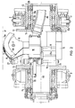
- the device carrier M which is used to carry out testing, measuring and / or processing operations from the inside the pipeline R serves and is provided with appropriate devices. It can therefore also be referred to as an internal pipe manipulator, which is used for checking and processing wall and weld seams from the inside.
- an equipment carrier can also be used for elongated cylindrical containers. Essential Lich is that the equipment carrier is invisible from the outside through the tube interior and can be locked in the respective working position. For this purpose, it has a work unit m2 and a feed unit m1. Both units are coupled to one another via an intermediate member m3 by means of the two cardanic joints g1, g2, so that the implement carrier can also drive through pipe bends, as shown.
- the feed unit m1 has an axially normal support flange f1 with pneumatically extendable clamping bodies 2 and guide rollers 3 on its outer circumference, furthermore a cry cylinder C1 with a stepping piston C2 which can be axially displaced therein, the cry cylinder firmly connected to the support flange f1 and the stepping piston C2 with its piston rod the intermediate link m3 is articulated at g1.
- a strand of supply lines 4 is brought to the feed unit; these are electrical, pneumatic power and control lines, and water lines can also be provided for cooling and rinsing purposes.
- a second support flange arranged at an axial distance from the first support flange f1 and supporting the ring with the guide rollers 3 is designated by f2.
- the working head K is mounted, which in the example shown has a grinding unit 5 with a TV camera TV, the grinding unit with the TV camera running all around on a U-shaped bracket 6 at corresponding pivot bearings in the center of the Support flanges f3, f4 is mounted.
- the motors for the rotary feed of the grinding unit and for swiveling its grinding wheel against the pipe seam are not shown for the sake of simplicity.
- Pneumatically extendable clamping feet and guide rollers on the outer circumference of the support flanges f3, f4 are again labeled 2 and 3, respectively.
- the feed unit m1 moves to the left when pressure is applied to the left side of the walking piston.
- the device carrier inside the tube can advance as many piston strokes or partial piston strokes to the left, ie up the tube, but can also be moved in the other direction to remove the device carrier.
- the equipment carrier is centered automatically on the pipe center R0.
- FIG. 1 is modified in comparison to the lower one in that its front working head is designed as a cleaning device for the inner peripheral surfaces of the pipeline R.
- rotating brushes 7, in particular steel wire brushes are mounted on the working head m2, which can be pressed against the inner wall surfaces to be cleaned.
- Adjustable with the brushes 7, ie. Rotatable in the circumferential direction and movable against the inner wall of the tube, a suction nozzle 8 which can be aligned with the brush engagement area is mounted, which, as the radial top view shows, is slit-shaped.
- suction nozzle 8 and the brushes 7 on a sector-shaped Brush holder 9 is arranged, which in turn is attached to a box-shaped support 10, the latter is mounted on guide rods 11 radially outwards and inwards.
- the support 10 and an axially oriented rotary motor 12 are fastened between the two turntables 13, the latter each having a hub 13a for rotatably mounting the cleaning head on the two support flanges f3, f4.
- the rotary motor 12 meshes with a pinion 12a on the inner circumference of a ring gear 14, which is attached to the inside of the support flange f4.
- the rotary motor 12 which is expediently provided with a reduction gear, can thus slowly set the cleaning head in rotation in the circumferential direction.
- a pneumatic adjusting cylinder is arranged inside the support 10, the piston of which is connected to the brush sector 9. Arrows within the brush sector indicate the start-up and feed movements.
- the suction nozzle 8 is connected to the suction side 15s of an injector 15, the pressure side of which is designated 15d, via an elastic line 8a which opens into a corresponding cavity of the support 10 and is guided through the hub of the plate 13.
- the propellant nozzle 16 of the injector 15, which is designed as a Laval nozzle, is acted upon by a propellant line 17 which is led to the latter from the outside and which is preferably a compressed air line.
- the drive nozzle 16 is followed by a mixing chamber 18 and the diffuser 19, the latter of which opens into the dust bag 20.
- the latter is connected with a flange 20a to the diffuser flange 19a in a sealing manner by means of a union nut 21.
- the housing 22 of the The injector is attached to the outside of the support flange f3 with a flange on the foot side.
- the propellant flow see arrow 17t, creates a strong suction at the outlet of the Laval nozzle 16, which takes effect via the flow connection at the inlet of the suction nozzle 8 and causes a very effective suction.
- the extracted dirt and metal particles are collected in the dust bag 20, which has a fine, dustproof but air-permeable fabric.
- This additional line 23 can be laid within the supply line 4. In this case, a particularly simple junction through the hub of the lower turntable 13 is possible. Basically, however, a branch from the propellant line 17 is also conceivable.
- the blowing agent line 17 a flexible, reinforced hose line, is unwound from a suitable line storage device from the other pipe end A2. If, after the end of the operation, the device carrier is removed again through the end A1, the propellant line 17 is uncoupled from the injector and rolled in from the other pipe end A2.
- Fig. 2 shows more clearly than Fig. 1 that an approximately circular sector-shaped, adapted to the inner wall curvature brush holder 9 (with 7 indicated brush bristles) * ) lowered, connected and according to the driving program on or aligned obliquely to the pipe axis transverse plane and with its brushes 7 projecting beyond the arcuate outer circumference 9a and being elastically adjustable against the wall inner circumference R ', can be moved in the pipe circumferential direction, ie around the pipe axis R0.
- the suction nozzle 8 is designed as an arcuate slot nozzle, which is connected downstream of the brush arc in the particle flight direction, which would mean a brush rotation direction according to arrow 7 '.
- FIG. 2 A variation is made in FIG. 2 in comparison to FIG. 1 in that the pinion 12a of the rotary motor 12 does not rotate on the inner circumference of a toothed ring 14 fixed to the supporting flange, but rather on the outer circumference of such a flange.
- the middle guide rod 11a belongs to a pneumatic piston which can be acted upon from two sides, the cylinder of which is structurally combined with the box-shaped support 10. It can also be clearly seen that the two turntables 13 are connected to one another in a torsionally rigid manner via a base frame 24, on which the one ends of the guide rods 11, 11a are anchored.
- the hubs 13a of the turntables 13 are each rotatably supported on the support flanges f3 and, f4 by means of thrust bearings 25 and support bearings 26.
- Guide balls 27 in the region of the two bow ends of the brush sector 9 ensure rolling friction on the inner circumference of the tube when the brushes wear out. They protrude somewhat further radially than the brush carrier arch 9b.
- FIG. 3 and FIG. 4 show a modification with a partial ring of individual brushes 70 rotating about their own axis and which can be pressed elastically against the inner wall, the rotary movement of the individual brushes 70 (Arrow 70 ') is still superimposed on the feed movement in the pipe circumferential direction according to arrow 7'.
- the individual brushes 70 each form an angle of attack ⁇ to the wall or pipe axis direction RO.
- the brush shafts are coupled to one another via friction wheels and belt drives 28, the drive motor for the individual brushes not being shown.
- rotating individual brushes 700 are aligned with their axes of rotation transverse to the pipe axis and have a barrel-like outer contour 29 adapted to the inner circumference of the wall.
- the drive can take place via a flexible shaft (not shown in detail).
- the equipment carrier only needs to be axially displaced for the purpose of pipe cleaning, but does not have to be reinserted into the pipe.
- the three-part design of the equipment carrier shown with the links m1, m2 and m3 has the advantage of a lower weight and better mobility compared to a five-part link.
- the work unit m2 as a combination unit with grinding head and cleaning head. Instead of the grinding head, other working heads (e.g. for welding, milling, ultrasonic testing, etc.) can of course also be coupled to the feed unit m1.
Applications Claiming Priority (2)
| Application Number | Priority Date | Filing Date | Title |
|---|---|---|---|
| DE3139691 | 1981-10-06 | ||
| DE19813139691 DE3139691A1 (de) | 1981-10-06 | 1981-10-06 | Reinigungsvorrichtung fuer die innenumfangsflaechen von rohrleitungen oder hohlzylindrischen behaeltern, insbesondere an rohrinnen-manipulatoren |
Publications (2)
| Publication Number | Publication Date |
|---|---|
| EP0076434A1 true EP0076434A1 (fr) | 1983-04-13 |
| EP0076434B1 EP0076434B1 (fr) | 1986-03-19 |
Family
ID=6143511
Family Applications (1)
| Application Number | Title | Priority Date | Filing Date |
|---|---|---|---|
| EP82108816A Expired EP0076434B1 (fr) | 1981-10-06 | 1982-09-23 | Manipulateur automoteur pour le traitement de la surface interne d'une tuyauterie ronde ou d'un reservoir cylindryque creux |
Country Status (5)
| Country | Link |
|---|---|
| US (1) | US4473921A (fr) |
| EP (1) | EP0076434B1 (fr) |
| JP (1) | JPS5874177A (fr) |
| DE (1) | DE3139691A1 (fr) |
| ES (1) | ES8306968A1 (fr) |
Cited By (8)
| Publication number | Priority date | Publication date | Assignee | Title |
|---|---|---|---|---|
| EP0104610A2 (fr) * | 1982-09-23 | 1984-04-04 | Union Carbide Corporation | Passage d'un tuyau à l'intérieur d'une conduite comportant des courbes |
| GB2159911A (en) * | 1984-06-07 | 1985-12-11 | British Gas Corp | Pipeline cleaning apparatus |
| FR2585604A1 (fr) * | 1985-08-02 | 1987-02-06 | Lacor Jacques | Dispositif pneumatique destine a capter les emanations aux points de soudage pour les transferer au-dela de l'atmosphere respiree par le personnel du poste de travail |
| FR2664184A1 (fr) * | 1990-07-04 | 1992-01-10 | Assainissement Produits Indls | Procede d'intervention sur des surfaces internes d'enceintes ou de gaines, dispositif multifonctionnel de nettoyage ou de traitement des surfaces internes. |
| EP0474233A1 (fr) * | 1990-09-07 | 1992-03-11 | F.B. LEHMANN Maschinenfabrik GmbH | Racleur pour système de tuyaux |
| WO1999013995A1 (fr) * | 1997-09-13 | 1999-03-25 | Slovensky Plynárensky Priemysel, S^¿.P. | Dispositif de nettoyage de l'interieur de conduites |
| CN115465994A (zh) * | 2022-09-20 | 2022-12-13 | 张敏 | 一种含盐浓度高的有机废水处理系统及方法 |
| CN116727378A (zh) * | 2023-08-11 | 2023-09-12 | 山西新翔环保科技有限公司 | 一种铝灰分选除尘系统 |
Families Citing this family (46)
| Publication number | Priority date | Publication date | Assignee | Title |
|---|---|---|---|---|
| FR2554520B1 (fr) * | 1983-11-09 | 1986-05-02 | Elf France | Dispositif de fixation rotative d'un element dans un tube |
| FI834468A (fi) * | 1983-12-07 | 1985-06-08 | Vilho Ilmari Hinkkanen | Rensningsanordning foer ventilationskanaler. |
| DE3614046A1 (de) * | 1985-05-09 | 1986-11-20 | EAB Electronic-Apparate-Bau GmbH, 8984 Riezlern | Vorrichtung zum reinigen von verlegten rohren |
| JPS6271586A (ja) * | 1985-09-25 | 1987-04-02 | 東洋ライニング株式会社 | パイプのクリ−ニング装置 |
| US4763678A (en) * | 1986-12-30 | 1988-08-16 | Mayo Medical Resources | Cleaning apparatus for elongated enclosed channel devices |
| CA2065329A1 (fr) * | 1989-08-30 | 1991-03-01 | John William Albrecht | Nettoyeur pour systeme de depot chimique en phase gazeuse |
| AU644607B2 (en) * | 1989-08-30 | 1993-12-16 | C.V.D. System Cleaners Corporation | Chemical vapor deposition system cleaner |
| US5109562A (en) * | 1989-08-30 | 1992-05-05 | C.V.D. System Cleaners Corporation | Chemical vapor deposition system cleaner |
| FR2656733A1 (fr) * | 1989-12-28 | 1991-07-05 | Framatome Sa | Dispositif de decontamination par abrasion de la surface interieure d'une canalisation. |
| US5122193A (en) * | 1990-08-10 | 1992-06-16 | Albuquerque Underground, Inc. | Pipe cleaning modules and systems and methods for their use |
| US5435854A (en) * | 1990-08-10 | 1995-07-25 | Pipeline Sewer Services, Inc. | Pipe cleaning modules and systems and methods for their use |
| DE4309026A1 (de) * | 1992-09-18 | 1994-03-24 | Sailer Johann Dipl Ing | Arbeitsvorrichtung |
| DE9311145U1 (de) * | 1993-07-26 | 1994-11-24 | Siemens Ag | Einrichtung zum Prüfen oder Bearbeiten der Innenoberfläche einer Rohrleitung |
| DE4417727A1 (de) * | 1994-05-20 | 1995-11-23 | Gema Volstatic Ag | Schlauchbürste |
| DE4417728A1 (de) * | 1994-05-20 | 1995-11-23 | Gema Volstatic Ag | Bürstenvorrichtung zum Reinigen von Kanälen |
| US6035484A (en) * | 1994-08-15 | 2000-03-14 | Industrial Zurich Usa, Ltd. | H.V.A.C. duct cleaning system compressor |
| US5724701A (en) * | 1994-08-15 | 1998-03-10 | Jones; Edward Ames | H.V.A.C. duct cleaning system |
| US5735016A (en) * | 1994-10-21 | 1998-04-07 | Clean-Aire International, Inc. | Duct cleaning apparatus |
| US5584093A (en) * | 1994-10-21 | 1996-12-17 | Clean-Aire International, Inc. | Duct cleaning apparatus |
| CA2144679C (fr) * | 1995-03-15 | 2006-10-24 | Bill Hendrix | Dispositif de nettoyage de conduit |
| JP3554911B2 (ja) * | 1996-12-10 | 2004-08-18 | エム・テイ・システム株式会社 | ダクト清掃用ロボットシステム |
| FR2767179B1 (fr) * | 1997-08-08 | 1999-09-10 | Coflexip | Systeme multi-outils utilisable pour le raccordement de conduites |
| US6180952B1 (en) * | 1998-04-03 | 2001-01-30 | Advanced Energy Systems, Inc. | Holder assembly system and method in an emitted energy system for photolithography |
| US6820653B1 (en) * | 1999-04-12 | 2004-11-23 | Carnegie Mellon University | Pipe inspection and repair system |
| US6917176B2 (en) * | 2001-03-07 | 2005-07-12 | Carnegie Mellon University | Gas main robotic inspection system |
| US6813810B2 (en) * | 2002-04-12 | 2004-11-09 | Merlin D. Beynon | Vacuum nozzle assembly and system |
| US20050109375A1 (en) * | 2003-11-26 | 2005-05-26 | Scott Peterson | Vent cleaning system |
| JP2005324163A (ja) * | 2004-05-17 | 2005-11-24 | Zenitaka Corp | 垂直円筒体内の清掃装置 |
| US7258359B2 (en) * | 2005-01-24 | 2007-08-21 | Wooten Metal, Inc. | Trailer hitch assembly |
| DE102005025736A1 (de) * | 2005-06-04 | 2006-12-07 | Daimlerchrysler Ag | Verfahren zum Entfernen von an einer Werkstückoberfläche anhaftenden Schweißperlen |
| US20080001005A1 (en) * | 2006-07-02 | 2008-01-03 | Lance Weaver | Apparatus for evenly applying liquids to interior surfaces |
| US20090307891A1 (en) * | 2008-06-17 | 2009-12-17 | Ge-Hitachi Nuclear Energy Americas Llc | Method and apparatus for remotely inspecting and/or treating welds, pipes, vessels and/or other components used in reactor coolant systems or other process applications |
| DE102009018796A1 (de) | 2009-04-24 | 2009-12-03 | Daimler Ag | Reinigungsvorrichtung für Kraftfahrzeugbauteile |
| CA2732377A1 (fr) * | 2010-02-22 | 2011-08-22 | Jeffrey S. Tinlin | Sonde d'inspection a jet pour interieur de canalisation |
| DE202011107597U1 (de) | 2011-11-08 | 2012-01-12 | Berthold Thoma | Anlage zur Reinigung von Rohrinnenflächen von und mit metallischem Strahlgut |
| US20180158557A1 (en) * | 2015-04-30 | 2018-06-07 | Ingenieria Y Marketing, S.A. | Device for Cleaning the Cover Flange of the Reactor Vessel in a Nuclear Plant |
| CN104923502B (zh) * | 2015-06-03 | 2016-10-19 | 中信戴卡股份有限公司 | 一种车轮在线清扫装置 |
| US10151097B2 (en) | 2015-09-17 | 2018-12-11 | Osvaldo Benedid | Sewer line root cleaning and repair system |
| CN106311687B (zh) * | 2016-08-29 | 2018-12-04 | 山东胜伟盐碱地科技有限公司 | 用于清理滤料波管的清理管 |
| CN107051990A (zh) * | 2016-10-18 | 2017-08-18 | 天津市华诺盛源科技有限公司 | 一种适用于管内壁的新型自动除尘装置 |
| US11162919B2 (en) * | 2019-05-20 | 2021-11-02 | Saudi Arabian Oil Company | Ultrasonic based internal inspection of tubes |
| CN110201951B (zh) * | 2019-06-26 | 2021-04-09 | 郑州旭飞光电科技有限公司 | 一种管道内壁处理装置以及处理方法 |
| US11459185B1 (en) * | 2021-05-06 | 2022-10-04 | INMAR Rx SOLUTIONS, INC. | Pneumatic transport system including pharmaceutical transport cleaner having a rotatable band and related methods |
| CN114160525B (zh) * | 2021-12-07 | 2022-09-30 | 湖南大学 | 一种具有可移动吸头的容器底部残渣负压吸取系统 |
| CN115256458A (zh) * | 2022-07-07 | 2022-11-01 | 佰利天控制设备(北京)股份有限公司 | 一种自动控制并脱除高炉煤气中二氧化碳的装置 |
| CN116274218B (zh) * | 2023-03-09 | 2024-04-02 | 宁波格劳博智能工业有限公司 | 一种锂电池电解液罐外壁冷凝水的清除装备 |
Citations (6)
| Publication number | Priority date | Publication date | Assignee | Title |
|---|---|---|---|---|
| US1869730A (en) * | 1931-10-23 | 1932-08-02 | John S Antle | Apparatus for cleaning tubes |
| US2957189A (en) * | 1958-06-12 | 1960-10-25 | Osborn Mfg Co | Pipe cleaning pig |
| US2974337A (en) * | 1958-07-21 | 1961-03-14 | Alvin C White | Piston-type cleaner for pipe lines |
| DE2335868A1 (de) * | 1973-07-14 | 1975-01-30 | Helmut Hilger | Geraet zum reinigen langgestreckter hohlraeume |
| US4027349A (en) * | 1976-03-12 | 1977-06-07 | Midcon Pipeline Equipment Co. | Apparatus for brush-cleaning the interiors of pipes |
| GB2070493A (en) * | 1980-02-16 | 1981-09-09 | Bosch Gmbh Robert | Hand machine tool especially a sheet metal nibbler |
Family Cites Families (16)
| Publication number | Priority date | Publication date | Assignee | Title |
|---|---|---|---|---|
| US2275190A (en) * | 1940-03-18 | 1942-03-03 | William G Lowry | Water main cleaning device |
| US2273347A (en) * | 1940-04-19 | 1942-02-17 | Hubert R Crane | Dumbbell-joint pressure-line scraper |
| US2332984A (en) * | 1942-07-24 | 1943-10-26 | Brackeen Lloyd | Cleaning device for pipe lines |
| US2509604A (en) * | 1948-07-06 | 1950-05-30 | Delbert A Mcgregor | Bowling alley gutter cleaner |
| DE908215C (de) * | 1951-04-05 | 1954-04-01 | P Von Arx & Co A G | Maschine zur Behandlung der Innenflaeche von Rohrleitungen |
| GB750592A (en) * | 1954-05-21 | 1956-06-20 | Nat Water Main Cleaning Compan | Improvements relating to pipe-cleaning devices |
| US2909796A (en) * | 1957-02-27 | 1959-10-27 | Williamson Inc T | Pipeline scrapers |
| US2959798A (en) * | 1958-03-24 | 1960-11-15 | Champlin Oil & Refining Co | Pipe line cleaner |
| US3107386A (en) * | 1960-05-05 | 1963-10-22 | Mandin Hans August Rudolf | Cleaner nozzle with pulsating jet |
| US3446666A (en) * | 1966-08-29 | 1969-05-27 | Albert G Bodine | Sonic process and apparatus for cleaning pipes |
| US3708819A (en) * | 1970-06-05 | 1973-01-09 | M Breston | Apparatus for drying pipelines |
| US3800358A (en) * | 1972-05-08 | 1974-04-02 | J Ryan | Duct cleaning apparatus |
| US3967584A (en) * | 1973-09-19 | 1976-07-06 | Nippon Kokan Kabushiki Kaisha | Self-running and automatic cleaning coating machine for internal wall of pipe |
| US3946459A (en) * | 1974-07-19 | 1976-03-30 | Lipe Rollway Corporation | Self-propelled pipe cleaner |
| US4044420A (en) * | 1974-08-09 | 1977-08-30 | Hanson Douglas R | Pan cleaning apparatus |
| DE3111814A1 (de) * | 1981-03-25 | 1982-10-07 | Kraftwerk Union AG, 4330 Mülheim | Selbstfahrender rohrinnenmanipulator zum fernbedienten transportieren von pruefgeraeten und werkzeugen laengs vorgegebener vorschubbahnen, vorzugsweise fuer kernkraftanlagen |
-
1981
- 1981-10-06 DE DE19813139691 patent/DE3139691A1/de not_active Ceased
-
1982
- 1982-09-17 US US06/419,596 patent/US4473921A/en not_active Expired - Fee Related
- 1982-09-23 EP EP82108816A patent/EP0076434B1/fr not_active Expired
- 1982-10-04 JP JP57174428A patent/JPS5874177A/ja active Pending
- 1982-10-05 ES ES516236A patent/ES8306968A1/es not_active Expired
Patent Citations (6)
| Publication number | Priority date | Publication date | Assignee | Title |
|---|---|---|---|---|
| US1869730A (en) * | 1931-10-23 | 1932-08-02 | John S Antle | Apparatus for cleaning tubes |
| US2957189A (en) * | 1958-06-12 | 1960-10-25 | Osborn Mfg Co | Pipe cleaning pig |
| US2974337A (en) * | 1958-07-21 | 1961-03-14 | Alvin C White | Piston-type cleaner for pipe lines |
| DE2335868A1 (de) * | 1973-07-14 | 1975-01-30 | Helmut Hilger | Geraet zum reinigen langgestreckter hohlraeume |
| US4027349A (en) * | 1976-03-12 | 1977-06-07 | Midcon Pipeline Equipment Co. | Apparatus for brush-cleaning the interiors of pipes |
| GB2070493A (en) * | 1980-02-16 | 1981-09-09 | Bosch Gmbh Robert | Hand machine tool especially a sheet metal nibbler |
Cited By (11)
| Publication number | Priority date | Publication date | Assignee | Title |
|---|---|---|---|---|
| EP0104610A2 (fr) * | 1982-09-23 | 1984-04-04 | Union Carbide Corporation | Passage d'un tuyau à l'intérieur d'une conduite comportant des courbes |
| EP0104610A3 (en) * | 1982-09-23 | 1986-03-12 | Union Carbide Corporation | Passage of a transit line through a conduit containing bends |
| GB2159911A (en) * | 1984-06-07 | 1985-12-11 | British Gas Corp | Pipeline cleaning apparatus |
| FR2585604A1 (fr) * | 1985-08-02 | 1987-02-06 | Lacor Jacques | Dispositif pneumatique destine a capter les emanations aux points de soudage pour les transferer au-dela de l'atmosphere respiree par le personnel du poste de travail |
| FR2664184A1 (fr) * | 1990-07-04 | 1992-01-10 | Assainissement Produits Indls | Procede d'intervention sur des surfaces internes d'enceintes ou de gaines, dispositif multifonctionnel de nettoyage ou de traitement des surfaces internes. |
| EP0474233A1 (fr) * | 1990-09-07 | 1992-03-11 | F.B. LEHMANN Maschinenfabrik GmbH | Racleur pour système de tuyaux |
| WO1999013995A1 (fr) * | 1997-09-13 | 1999-03-25 | Slovensky Plynárensky Priemysel, S^¿.P. | Dispositif de nettoyage de l'interieur de conduites |
| CN115465994A (zh) * | 2022-09-20 | 2022-12-13 | 张敏 | 一种含盐浓度高的有机废水处理系统及方法 |
| CN115465994B (zh) * | 2022-09-20 | 2023-09-08 | 浙江宣达环境科技股份有限公司 | 一种含盐浓度高的有机废水处理系统及方法 |
| CN116727378A (zh) * | 2023-08-11 | 2023-09-12 | 山西新翔环保科技有限公司 | 一种铝灰分选除尘系统 |
| CN116727378B (zh) * | 2023-08-11 | 2023-11-10 | 山西新翔环保科技有限公司 | 一种铝灰分选除尘系统 |
Also Published As
| Publication number | Publication date |
|---|---|
| US4473921A (en) | 1984-10-02 |
| ES516236A0 (es) | 1983-06-16 |
| ES8306968A1 (es) | 1983-06-16 |
| EP0076434B1 (fr) | 1986-03-19 |
| DE3139691A1 (de) | 1983-04-21 |
| JPS5874177A (ja) | 1983-05-04 |
Similar Documents
| Publication | Publication Date | Title |
|---|---|---|
| EP0076434A1 (fr) | Manipulateur automoteur pour le traitement de la surface interne d'une tuyauterie ronde ou d'un reservoir cylindryque creux | |
| DE2654933C2 (de) | Gelenkupplungseinrichtung für Rohrleitungen, insbesondere für Absaugeinrichtungen | |
| DE69810943T2 (de) | Vorrichtung zur reinigung des inneren von rohrleitungen | |
| EP1973674B1 (fr) | Ecouvillon de netoyage | |
| EP0307416B1 (fr) | Machine pour reparer et rendre etanches des conduites dans lesquelles on ne peut marcher | |
| EP3017885A1 (fr) | Dispositif de nettoyage de tuyaux | |
| DE4017998C2 (fr) | ||
| DE2457034A1 (de) | Verfahren und vorrichtung zur reinigung von spinnturbinen einer spinnmaschine | |
| EP0146833B1 (fr) | Dispositif pour le polissage électrolytique des surfaces intérieures d'objets cylindriques creux | |
| DE3224498A1 (de) | Rohrmolch | |
| DE2538793A1 (de) | Umlaufender sandstrahl-geblaesekopf | |
| DE3446055A1 (de) | Verfahren und vorrichtung zum schleifen der innenflaechen grosslumiger gerader und gekruemmter rohre | |
| DE3139692A1 (de) | Geraetetraeger, insbesondere rohrinnen-manipulator | |
| DE102009040138A1 (de) | Wasch- und Reinigungssystem für Behälterbehandlungsmaschinen | |
| DE2348265A1 (de) | Vorrichtung zur abtastung einer gekruemmten flaeche | |
| DE19529782A1 (de) | Selbstfahrender Rohrmanipulator | |
| DE2623665A1 (de) | Verfahren und vorrichtung zum reinigen eines in der achse eines reaktors angeordneten rotierenden ruehrwerkes mit dicht an den reaktorwaenden vorbeigehendem ruehrorgan | |
| DE2528483B2 (de) | Vorrichtung zum entladen von mit schlecht fliessendem, brueckenbildendem schuettgut beladenen schiffen | |
| CH642294A5 (en) | Process and apparatus for the anti-corrosion treatment of the inner surface of a tubular hollow body | |
| DE10360649A1 (de) | Trockenreinigungseinrichtung, insbesondere Entstaubungsanlage, zur Vorbehandlung zu lackierender Fahrzeugkarosserien | |
| DE4240856C2 (de) | Tauchfähige Reinigungsvorrichtung | |
| DE4105799C2 (fr) | ||
| DE102018130802B3 (de) | Vorrichtung zur Ausführung von Arbeitsvorgängen in Lagertanks für Erdölprodukte | |
| EP0186031B1 (fr) | Tête de manipulateur avec dispositif de meulage pour tuyaux ou tuyauteries | |
| CH193300A (de) | Gerät zur Oberflächenbehandlung, insbesondere zum Reinigen von Fenstern, Wänden etc. |
Legal Events
| Date | Code | Title | Description |
|---|---|---|---|
| PUAI | Public reference made under article 153(3) epc to a published international application that has entered the european phase |
Free format text: ORIGINAL CODE: 0009012 |
|
| AK | Designated contracting states |
Designated state(s): CH FR GB IT LI NL SE |
|
| 17P | Request for examination filed |
Effective date: 19830426 |
|
| GRAA | (expected) grant |
Free format text: ORIGINAL CODE: 0009210 |
|
| ITF | It: translation for a ep patent filed |
Owner name: STUDIO JAUMANN |
|
| AK | Designated contracting states |
Kind code of ref document: B1 Designated state(s): CH FR GB IT LI NL SE |
|
| ET | Fr: translation filed | ||
| PLBE | No opposition filed within time limit |
Free format text: ORIGINAL CODE: 0009261 |
|
| STAA | Information on the status of an ep patent application or granted ep patent |
Free format text: STATUS: NO OPPOSITION FILED WITHIN TIME LIMIT |
|
| 26N | No opposition filed | ||
| PGFP | Annual fee paid to national office [announced via postgrant information from national office to epo] |
Ref country code: NL Payment date: 19870930 Year of fee payment: 6 |
|
| PG25 | Lapsed in a contracting state [announced via postgrant information from national office to epo] |
Ref country code: GB Effective date: 19880923 |
|
| PG25 | Lapsed in a contracting state [announced via postgrant information from national office to epo] |
Ref country code: LI Effective date: 19880930 Ref country code: CH Effective date: 19880930 |
|
| PG25 | Lapsed in a contracting state [announced via postgrant information from national office to epo] |
Ref country code: NL Effective date: 19890401 |
|
| NLV4 | Nl: lapsed or anulled due to non-payment of the annual fee | ||
| REG | Reference to a national code |
Ref country code: CH Ref legal event code: PL |
|
| GBPC | Gb: european patent ceased through non-payment of renewal fee | ||
| PGFP | Annual fee paid to national office [announced via postgrant information from national office to epo] |
Ref country code: SE Payment date: 19890912 Year of fee payment: 8 |
|
| PGFP | Annual fee paid to national office [announced via postgrant information from national office to epo] |
Ref country code: FR Payment date: 19890928 Year of fee payment: 8 |
|
| PG25 | Lapsed in a contracting state [announced via postgrant information from national office to epo] |
Ref country code: SE Effective date: 19900924 |
|
| PG25 | Lapsed in a contracting state [announced via postgrant information from national office to epo] |
Ref country code: FR Effective date: 19910530 |
|
| REG | Reference to a national code |
Ref country code: FR Ref legal event code: ST |
|
| EUG | Se: european patent has lapsed |
Ref document number: 82108816.8 Effective date: 19910527 |