EP0076434A1 - Automotive manipulator for the treatment of the inner surface of a round pipe or of a hollow cylindrical container - Google Patents
Automotive manipulator for the treatment of the inner surface of a round pipe or of a hollow cylindrical container Download PDFInfo
- Publication number
- EP0076434A1 EP0076434A1 EP82108816A EP82108816A EP0076434A1 EP 0076434 A1 EP0076434 A1 EP 0076434A1 EP 82108816 A EP82108816 A EP 82108816A EP 82108816 A EP82108816 A EP 82108816A EP 0076434 A1 EP0076434 A1 EP 0076434A1
- Authority
- EP
- European Patent Office
- Prior art keywords
- cleaning device
- wall
- working head
- brushes
- injector
- Prior art date
- Legal status (The legal status is an assumption and is not a legal conclusion. Google has not performed a legal analysis and makes no representation as to the accuracy of the status listed.)
- Granted
Links
Images

Classifications
-
- B—PERFORMING OPERATIONS; TRANSPORTING
- B08—CLEANING
- B08B—CLEANING IN GENERAL; PREVENTION OF FOULING IN GENERAL
- B08B15/00—Preventing escape of dirt or fumes from the area where they are produced; Collecting or removing dirt or fumes from that area
- B08B15/04—Preventing escape of dirt or fumes from the area where they are produced; Collecting or removing dirt or fumes from that area from a small area, e.g. a tool
-
- B—PERFORMING OPERATIONS; TRANSPORTING
- B08—CLEANING
- B08B—CLEANING IN GENERAL; PREVENTION OF FOULING IN GENERAL
- B08B9/00—Cleaning hollow articles by methods or apparatus specially adapted thereto
- B08B9/02—Cleaning pipes or tubes or systems of pipes or tubes
- B08B9/027—Cleaning the internal surfaces; Removal of blockages
- B08B9/032—Cleaning the internal surfaces; Removal of blockages by the mechanical action of a moving fluid, e.g. by flushing
- B08B9/035—Cleaning the internal surfaces; Removal of blockages by the mechanical action of a moving fluid, e.g. by flushing by suction
-
- B—PERFORMING OPERATIONS; TRANSPORTING
- B08—CLEANING
- B08B—CLEANING IN GENERAL; PREVENTION OF FOULING IN GENERAL
- B08B9/00—Cleaning hollow articles by methods or apparatus specially adapted thereto
- B08B9/02—Cleaning pipes or tubes or systems of pipes or tubes
- B08B9/027—Cleaning the internal surfaces; Removal of blockages
- B08B9/04—Cleaning the internal surfaces; Removal of blockages using cleaning devices introduced into and moved along the pipes
- B08B9/043—Cleaning the internal surfaces; Removal of blockages using cleaning devices introduced into and moved along the pipes moved by externally powered mechanical linkage, e.g. pushed or drawn through the pipes
- B08B9/047—Cleaning the internal surfaces; Removal of blockages using cleaning devices introduced into and moved along the pipes moved by externally powered mechanical linkage, e.g. pushed or drawn through the pipes the cleaning devices having internal motors, e.g. turbines for powering cleaning tools
Landscapes
- Engineering & Computer Science (AREA)
- Mechanical Engineering (AREA)
- Cleaning In General (AREA)
- Nozzles (AREA)
Abstract
Reinigungsvorrichtung für die Innenumfangsflächen von Rohrleitungen (R) oder hohlyzylindrischen Behältern an mit Prüf-, Meß- und/oder Bearbeitungsgeräten ausgerüsteten Geräteträgern (M), welche durch das Innere der Rohrleitungen oder Behälter von außen unsichtbar transportierbar und in der jeweiligen Arbeitsposition arretierbar sind, insbesondere von Rohrinnen-Manipulatoren zur Wand- und Schweißnaht-Kontrolle und -Bearbeitung von innen, wobie die an mindestens einem Arbeitskopf (K) gelagerten Geräte in Umfangs- und/oder in axialer Richtung längs definierter Vorschubbahnen bewegbar sind. Am Arbeitskopf (K) sind rotierende, gegen die zu reinigenden Innenwandflächen andrückbare Bürsten (7) und ferner mindestens eine auf den Bürsteneingriffsbereich ausrichtbare Absaugdüse (8) gelagert. Die Absaugdüse (8) ist an die Saugseite eines Injektors (15) angeschlossen, dessen Treibdüse (16) von einer an den Injektor (15) von außen herangeführten Treibmittelleitung (17) beaufschlagt und dessen Abströmseite ein Staubfangsack (20) nachgeschaltet ist.Cleaning device for the inner circumferential surfaces of pipes (R) or hollow cylindrical containers on equipment carriers (M) equipped with testing, measuring and / or processing devices, which can be invisibly transported from the outside through the inside of the pipes or containers and can be locked in the respective working position, in particular of pipe manipulators for wall and weld inspection and processing from the inside, the devices mounted on at least one working head (K) being movable in the circumferential and / or axial direction along defined feed paths. Rotating brushes (7) which can be pressed against the inner wall surfaces to be cleaned and furthermore at least one suction nozzle (8) which can be aligned with the brush engagement area are mounted on the working head (K). The suction nozzle (8) is connected to the suction side of an injector (15), the propellant nozzle (16) of which is acted upon by a propellant line (17) led from the outside to the injector (15) and the downstream side of which is followed by a dust bag (20).
Description
Die Erfindung bezieht sich auf eine Reinigungsvorrichtung für die Innenumfangsflächen von Rohrleitungen oder hohlzylindrischen Behältern an mit Prüf-, Meß-und/oder Bearbeitungsgeräten ausgerüsteten Geräteträgern, insbesondere von Rohrinnen-Manipulatoren, gemäß Oberbegriff des Anspruchs 1.The invention relates to a cleaning device for the inner circumferential surfaces of pipelines or hollow cylindrical containers on device carriers equipped with testing, measuring and / or processing devices, in particular pipe manipulators, according to the preamble of claim 1.
Ein Geräteträger der im Gattungsbegriff umschriebenen Aufbauform ist z.B. in der älteren Anmeldung P 31 11 814.3 näher erläutert. Solche Geräteträger haben große Bedeutung zur Innen-Kontrolle und -Bearbeitung von Rohrleitungen. So kann man mit ihnen schleifen, schweißen, ultraschall-prüfen, wirbelstrom-prüfen, isotopen-prüfen, innenplattieren, mittels Fernsehsystemen inspizieren, um einige wichtige Anwendungsfälle zu nennen. Ein besonderes Problem dabei ist das Absaugen des Schleifstaubes und der Schweißperlen. Reinigungsvorgänge sind auch dann erwünscht, wenn man Rohrinnenpartien fotografieren oder mit Fernsehkameras bzw. mit Lichtleiter-Endoskopen inspizieren möchte. Einerseits haften die Schmutz- bzw. Metallpartikel teilweise relativ fest an der Innenoberfläche, andererseits sind bei Rohrleitungslängen in der Größenordnung von 20 bis 40 m, die noch dazu mit Gefälle verlegt sind, erhebliche Druckdifferenzen bei der Absaugung zu überwinden.An equipment carrier of the design described in the generic term is e.g. in the earlier application P 31 11 814.3 explained in more detail. Such equipment carriers are very important for the internal control and processing of pipelines. You can use them to grind, weld, ultrasound, eddy current, isotope, interior plating, television system inspection, to name a few important applications. A particular problem is the extraction of the grinding dust and the welding beads. Cleaning processes are also desirable if you want to take pictures of the inside of pipes or inspect them with television cameras or fiber optic endoscopes. On the one hand, the dirt or metal particles sometimes adhere relatively firmly to the inner surface, on the other hand, with pipeline lengths of the order of 20 to 40 m, which are also laid with a slope, considerable pressure differences have to be overcome during suction.
Der Erfindung liegt die.Aufgabe zugrunde, eine Reinigungsvorrichtung gemäß Gattungsbegriff zu schaffen, welche die geschilderten Anforderungen erfüllt und mit der eine sehr effektive Reinigung bei hoher Saugleistung erreicht werden kann.The invention is based on the object of creating a cleaning device according to the generic term, which fulfills the described requirements and with which very effective cleaning with high suction power can be achieved.
Erfindungsgemäß wird die gestellte Aufgabe durch die im Kennzeichen des Anspruchs 1 angegebenen Merkmale gelöst. Vorteilhafte Weiterbildungen sind in den Unteransprüchen 2 bis 11 angegeben. Die mit der Erfindung erzielbaren Vorteile sind vor allem darin zu sehen, daß im Inneren von hohlzylindrischen langgestreckten Körpern verfahrbare Geräteträger, insbesondere Rohrinnen-Manipulatoren, nun auf einfache Weise mit einem Reinigungskopf ausgerüstet werden können, welcher die erforderliche Reinigung vor und nach den Prüf-, Meß-oder Bearbeitungsvorgängen ausführen kann. Grundsätzlich ist es sogar möglich, z.B. einen Schleifkopf des Geräteträgers mit einer Reinigungsvorrichtung nach der Erfindung zu einem Schleif/Reinigungs-Kopf zu vereinigen, was den Vorteil hat, daß der Schleifstaub sofort beim Entstehen abgeführt wird. Als Bürsten kommen Drahtbürsten infrage, insbesondere Stahldrahtbürsten. Der Injektor wird bevorzugt mit Druckluft als Treibmittel beaufschlagt. Druckluft ist in jedem Kraftwerk bzw. Kernkraftwerk, dem bevorzugten Anwendungsgebiet der Geräteträger, vorhanden. Der besondere Vorteil von Druckluft als Treibmittel ist der, daß mühelos jede Saughöhe, die in praktischen Anwendungsfällen auftreten kann, überwunden wird.According to the invention, the object is achieved by the features specified in the characterizing part of claim 1. Advantageous further developments are specified in
Im folgenden wird anhand mehrerer Ausführungsbeispiele, die in der Zeichnung dargestellt sind, die Erfindung noch näher erläutert. Darin zeigt in zum Teil schematischer, stark vereinfachter Darstellung:
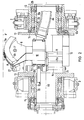
- Fig. 1 in ihrer unteren Hälfte einen Geräteträger, ausgebildet als Rohrinnen-Manipulator mit einem als Schleifkopf ausgebildeten Arbeitskopf in Arbeitsstellung innerhalb einer Rohrleitung und in ihrer oberen Hälfte den im Prinzip gleichartigen Geräteträger, jedoch mit einem Arbeitskopf,, der eine Reinigungsvorrichtung trägt, gleichfalls in Arbeitsstellung;
- Fig. 2 vergrößert im Detail, allerdings seitenvertauscht, den umlaufenden Support für Bürste und Absaugdüse;
- Fig. 3 in Draufsicht und
- Fig. 4 in Seitenansicht eine abgeänderte Ausführung eines Bürstensektors mit rotierenden Einzelbürsten, deren Drehachsen schräg zur Rohrachsrichtung verlaufen, und
- Fig. 5 in Draufsicht sowie
- Fig. 6 in Seitenansicht ein drittes Ausführungsbeispiel für einen Bürstensektor, bei dem die Achsen der rotierenden Einzelbürsten in einer rohrachsnormalen Ebene liegen.
- Fig. 1 in its lower half a device carrier, designed as a pipe manipulator with a working head designed as a grinding head in the working position within a pipeline and in its upper half the device carrier, which is basically the same, but with a working head, which carries a cleaning device, also in Working position;
- Fig. 2 enlarged in detail, but reversed sides, the all-round support for the brush and suction nozzle;
- Fig. 3 in plan view and
- Fig. 4 in side view of a modified version of a brush sector with rotating individual brushes, the axes of rotation of which run obliquely to the tube axis direction, and
- Fig. 5 in top view and
- Fig. 6 in side view of a third embodiment of a brush sector, in which the axes of the rotating individual brushes lie in a plane normal to the tube axis.
Innerhalb der S-förmig gekrümmten Rohrleitungspartie R eines Kraftwerkes, insbesondere Kernkraftwerkes, mit den über umlaufende Schweißnähte 1.1 und 1.2 verbundenen Rohrleitungsschüssen r1, r2, r3 befindet sich der Geräteträger M, welcher zur Ausführung von Prüf-, Meß- und/ oder Bearbeitungsvorgängen vom Inneren der Rohrleitung R aus dient und dazu mit entsprechenden Geräten versehen ist. Er kann deshalb auch als Rohrinnen-Manipulator bezeichnet werden, welcher zur Wand- und Schweißnaht-Kontrolle und -bearbeitung von innen dient. Grundsätzlich läßt sich ein solcher Geräteträger auch für langgestreckte zylindrische Behälter verwenden. Wesentlich ist, daß der Geräteträger von außen unsichtbar durch das Rohrinnere transportierbar und in der jeweiligen Arbeitsposition arretierbar ist. Er weist hierzu eine Arbeitseinheit m2 und eine Vorschubeinheit m1 auf. Beide Einheiten sind über ein Zwischenglied m3 mittels der beiden kardanischen Gelenke g1, g2 miteinander gekoppelt, so daß der Geräteträger auch Rohr- krümmungen, wie dargestellt, durchfahren kann.Within the S-shaped curved pipe section R of a power plant, in particular a nuclear power plant, with the pipe sections r1, r2, r3 connected via circumferential weld seams 1.1 and 1.2, there is the device carrier M, which is used to carry out testing, measuring and / or processing operations from the inside the pipeline R serves and is provided with appropriate devices. It can therefore also be referred to as an internal pipe manipulator, which is used for checking and processing wall and weld seams from the inside. In principle, such an equipment carrier can also be used for elongated cylindrical containers. Essential Lich is that the equipment carrier is invisible from the outside through the tube interior and can be locked in the respective working position. For this purpose, it has a work unit m2 and a feed unit m1. Both units are coupled to one another via an intermediate member m3 by means of the two cardanic joints g1, g2, so that the implement carrier can also drive through pipe bends, as shown.
Die Vorschubeinheit m1 weist einen achsnormalen Stützflansch f1 mit pneumatisch ausfahrbaren Klemmkörpern 2 und Führungsrollen 3 an seinem äußeren Umfang auf, ferner einen Schreitzylinder C1 mit darin axial verschiebbarem Schreitkolben C2, wobei der Schreitzylinder mit dem Stützflansch f1 fest verbunden und der Schreitkolben C2 mit seinen Kolbenstange an dem Zwischenglied m3 bei g1 angelenkt ist. An die Vorschubeinheit ist ein Strang von Versorgungsleitungen 4 herangeführt; es handelt sich dabei um elektrische, pneumatische Kraft- und Steuerleitungen, ferner können Wasserleitungen zu Kühl- und Spülzwecken vorgesehen sein. Ein in Axialabstand zum ersten Stützflansch f1 angeordneter und den Kranz mit den Führungsrollen 3 abstützender zweiter Stützflansch ist mit f2 bezeichnet.The feed unit m1 has an axially normal support flange f1 with pneumatically
Zwischen den beiden achsnormalen Stützflanschen f3 und f4 der Arbeitseinheit m2 ist der Arbeitskopf K gelagert, welcher im dargestellten Beispiel ein Schleifaggregat 5 mit Fernsehkamera TV aufweist, wobei das Schleifaggregat mit der Fernsehkamera umlaufend an einem U-förmigen Bügel 6-an entsprechenden Drehlagern im Zentrum der Stützflansche f3, f4 gelagert ist. Die Motore zum Drehvorschub des Schleifaggregates und zum Einschwenken seiner Schleifscheibe gegen die Rohrnaht sind der Einfachheit halber nicht dargestellt. Pneumatisch ausfahrbare Klemmfüße und Führungsrollen am Außenumfang der Stützflansche f3, f4 sind wieder mit 2 bzw. 3 bezeichnet.Between the two axially normal support flanges f3 and f4 of the working unit m2, the working head K is mounted, which in the example shown has a
Wenn die rechte Seite des Schreitkolben C2 mit Druckluft beaufschlagt wird, dann bewegt sich - bei arretierter Vorschubeinheit m1 (Klemmfüße 2 ausgefahren), dagegen bei gelöster Arbeitseinheit m2 (Klemmfüße 2 eingefahren) - letztere mit dem Schreitkolben nach links. Ist die Arbeitseinheit m2 arretiert und die Klemmverbindung bei der Vorschubeinheit m1 außer Eingriff gebracht, dann bewegt sich bei Druckbeaufschlagung der linken Schreitkolbenseite die Vorschubeinheit m1 nach links. Auf diese Weise kann der Geräteträger im Rohrinneren um beliebig viele Kolbenhübe oder auch Teilkolbenhübe nach links, d.h. rohraufwärts, fortschreiten, jedoch auch zum Herausnehmen des Geräteträgers in der anderen Richtung bewegt werden. Der Geräteträger zentriert sich dabei selbsttätig auf Rohrmitte R0. Der im oberen Teil der Fig. 1 dargestellte Geräteträger M ist im Vergleich zum unteren dadurch abgewandelt, daß sein frontseitiger Arbeitskopf als Reinigungsvorrichtung für die Innenumfangsflächen der Rohrleitung R ausgebildet ist. Dazu sind am Arbeitskopf m2 rotierende, gegen die zu reinigenden Innenwandflächen andrückbare Bürsten 7 gelagert, insbesondere Stahldrahtbürsten. Mit den Bürsten 7 verstellbar, dh. in Umfangsrichtung drehbar und gegen die Rohrinnenwand bewegbar, ist eine auf den Bürsteneingriffsbereich ausrichtbare Absaugdüse 8 gelagert, die, wie es die radiale Draufsicht zeigt, schlitzförmig ist. Aus Fig. 1 ist weiter erkennbar, daß die Saugdüse 8 und die Bürsten 7 an einem sektorförmigen Bürstenträger 9 angeordnet ist, der wiederum an einem kastenförmigen Support 10 befestigt ist, welch letzterer an Führungsstangen 11 radial auswärts und einwärts verschiebbar gelagert ist. Der Support 10 und ein axial orientierter Drehmotor 12 sind zwischen den beiden Drehtellern 13 befestigt, welch letztere je eine Nabe 13a zur drehbaren Lagerung des Reinigungskopfes an den beiden Stützflanschen f3, f4 aufwäsen. Der Drehmotor 12 kämmt mit einem Ritzel 12a am Innenumfang eines Zahnkranzes 14, welcher an der Innenseite des Stützflansches f4 befestigt ist. Der zweckmäßig mit einem Untersetzungsgetriebe versehene Drehmotor 12 kann also den Reinigungskopf in Umfangsrichtung langsam in Drehung versetzen. Zwecks pneumatischer Anstellung der Bürsten gegen die Rohrinnenwand ist im Inneren des Supports 10 ein pneumatischer Anstellzylinder angeordnet, dessen Kolben mit dem Bürstensektor 9 verbunden ist. Durch Pfeile sind innerhalb des Bürstensektors die Anstell- und die Vorschub-Bewegung angedeutet.If compressed air is applied to the right side of the walking piston C2, then - with the feed unit m1 locked (clamping
Die Absaugdüse 8 ist über eine elastische Leitung 8a, welche in einen entsprechenden Hohlraum des Supports 10 mündet und durch die Nabe des Tellers 13 hindurchgeführt ist, an die Saugseite 15s eines Injektors 15 angeschlossen, dessen Druckseite mit 15d bezeichnet ist. Die als Laval-Düse ausgebildete Treibdüse 16 des Injektors 15 wird von einer an diesen von außen herangeführten Treibmittelleitung 17 beaufschlagt, welche bevorzugt eine Druckluftleitung ist. In Strömungsrichtung gesehen folgt auf die Treibdüse 16 ein Mischraum 18 und der Diffusor 19, weich-letzterer in den Staubfangsack 20-mündet. Letzterer ist mit einem Flansch 20a an den Diffusorflansch 19a mittels einer Überwurfmutter 21 dichtend angeschlossen. Das Gehäuse 22 des Injektors ist mit einem fußseitigen Flansch an der Außenseite des Stützflansches f3 befestigt.The
Im Betrieb des Injektors wird durch den Treibmittelstrom, siehe Pfeil 17t, ein starker Sog am Ausgang der Laval-Düse 16 erzeugt, welcher über die Strömungsverbindung am Einlaß der Ansaugdüse 8 wirksam wird und eine sehr effektive Absaugung bewirkt. Die abgesaugten Schmutz- und Metall-Partikel werden im Staubfangsack 20 aufgefangen, welcher ein feines staubdichtes, jedoch luftdurchlässiges Gewebe aufweist. Es kann vorteilhaft sein, den Arbeitsraum der Bürste 7 und der Saugdüse 8 zur Verbesserung des Absaugvorganges mit zusätzlicher Druckluft zu beblasen, siehe gestrichelt angedeutete Druckluftleitung 23 mit Ventil V. Diese Zusatzleitung 23 kann innerhalb des Versorgungsstranges 4 verlegt sein. In diesem Falle ist eine besonders einfache Einmündung durch die Nabe des unteren Drehtellers 13 hindurch möglich. Grundsätzlich ist aber auch eine Abzweigung von der Treibmittelleitung 17 denkbar.During operation of the injector, the propellant flow, see
Bevor der Geräteträger M mit der Reinigungsvorrichtung vom Rohrende A1 eingeführt wird, . wird vom anderen Rohrende A2 die Treibmittelleitung 17, eine flexible, armierte Schlauchleitung, von einem geeigneten Leitungsspeicher abgespult. Wenn nach beendeter Operation der Geräteträger durch das Ende A1 wieder heraus-genommen wird, so wird die Treibmittelleitung 17 vom Injektor entkuppelt und vom-anderen Rohrende A2 her eingerollt.Before the device carrier M with the cleaning device is inserted from the pipe end A1. the blowing agent line 17, a flexible, reinforced hose line, is unwound from a suitable line storage device from the other pipe end A2. If, after the end of the operation, the device carrier is removed again through the end A1, the propellant line 17 is uncoupled from the injector and rolled in from the other pipe end A2.
Fig. 2 zeigt deutlicher als Fig. 1, daß ein etwa kreissektorförmiger, an die Innenwandkrümmung angepaßter Bürstenträger 9 (mit bei 7 angedeuteten Bürsten-Borsten) *) herabgelassen, angeschlossen und entsprechend dem Fahrprogramm auf- oder schräg zur rohrachsqueren Ebene ausgerichtet und mit seinen über den bogenförmigen Außenumfang 9a überstehenden, gegen den Wandinnenumfang R' elastisch anstellbaren Bürsten 7 in Rohrumfangsrichtung, d.h. um die Rohrachse R0, bewegbar ist. Die Absaugdüse 8 ist als bogenförmige Schlitzdüse ausgebildet, welche dem Bürstenbogen in Partikelflugrichtung nachgeschaltet ist, das würde eine Bürstendrehrichtung gemäß Pfeil 7' bedeuten. Gleiche Teile zu Fig. 1 sind in Fig. 2 auch mit den gleichen Bezugszeichen versehen. Eine Variation ist in Fig. 2 im Vergleich zu Fig. 1 insofern getroffen, als das Ritzel 12a des Drehmotors 12 nicht am Innenumfang eines stützflansch-festen Zahnkranzes 14 sondern am Außenumfang eines solchen Flansches umläuft. Die mittlere Führungsstange 11a gehört zu einem zweiseitig beaufschlagbaren pneumatischen Kolben, dessen Zylinder mit dem kastenförmigen Support 10 baulich vereinigt ist. Deutlich erkennbar ist auch, daß die beiden Drehteller 13 über einen Grundrahmen 24 drehsteif miteinander verbunden sind, an welchem die einen Enden der Führungsstangen 11, 11a verankert sind. Die Naben 13a der Drehteller 13 sind jeweils mittels Drucklagern 25 und Traglagern 26 an den Stützflanschen f3 bzw., f4 drehbar gelagert. Führungskugeln 27 im Bereich der beiden Bogenenden des Bürstensektors 9 gewährleisten eine rollende Reibung am Rohrinnenumfang bei Abnutzung der Bürsten. Sie stehen etwas weiter radial vor als der Bürstenträgerbogen 9b.Fig. 2 shows more clearly than Fig. 1 that an approximately circular sector-shaped, adapted to the inner wall curvature brush holder 9 (with 7 indicated brush bristles) * ) lowered, connected and according to the driving program on or aligned obliquely to the pipe axis transverse plane and with its
Fig. 3 und Fig. 4 zeigen eine Abwandlung, mit einem Teilkranz von jeweils um ihre eigene Achse rotierenden und gegen die Innenwand elastisch andrückbaren Einzelbürsten 70, wobei der Drehbewegung der Einzelbürsten 70 (Pfeil 70') noch die Vorschubbewegung in Rohrumfangsrichtung gemäß Pfeil 7' überlagert ist. Die Einzelbürsten 70 bilden dabei jeweils einen Anstellwinkel ∞ zur Wand- bzw. Rohrachsrichtung RO. Die Bürstenwellen sind untereinander über Reibräder und Riementriebe 28 miteinander gekoppelt, wobei der Antriebsmotor für die Einzelbürsten nicht dargestellt ist.3 and FIG. 4 show a modification with a partial ring of
Gemäß Fig. 5 und Fig. 6 sind rotierende Einzelbürsten 700 mit ihren Rotationsachsen rohrachsquer ausgerichtet und weisen dabei eine an den Wandinnenumfang angepaßte tonnenartige Außenkontur 29 auf. Der Antrieb kann dabei über eine biegsame Welle erfolgen (nicht näher dargestellt).According to FIGS. 5 and 6, rotating individual brushes 700 are aligned with their axes of rotation transverse to the pipe axis and have a barrel-like
Zurückkommend auf Fig. 1 kann man erkennen, daß eine Ankopplung der Reinigungsvorrichtung frontseitig an den unten in Fig. 1 dargestellten Arbeitskopf über ein weiteres Zwischenglied möglich wäre. In diesem Falle braucht zum Zwecke der Rohrreinigung der Geräteträger nur axial verschoben, muß aber nicht neu in das Rohr eingeführt werden. Die dargestellte dreigliedrige Ausführung des Geräteträgers mit den.Gliedern m1, m2 und m3 hat gegenüber einer fünfgliedrigen jedoch den Vorteil des geringen Gewichtes und der besseren Beweglichkeit. Es ist, wie eingangs schon erwähnt, auch möglich, die Arbeitseinheit m2 als Kombinationseinheit mit Schleifkopf und Reinigungskopf auszuführen. Anstelle des Schleifkopfes sind naturgemäß auch andere Arbeitsköpfe (z.B. zum Schweißen, Fräsen, Ultraschallprüfen usw.)-an die Vorschubeinheit m1 ankuppelbar.Returning to FIG. 1, it can be seen that a coupling of the cleaning device on the front side to the working head shown below in FIG. 1 would be possible via a further intermediate member. In this case, the equipment carrier only needs to be axially displaced for the purpose of pipe cleaning, but does not have to be reinserted into the pipe. The three-part design of the equipment carrier shown with the links m1, m2 and m3 has the advantage of a lower weight and better mobility compared to a five-part link. As already mentioned at the beginning, it is also possible to design the work unit m2 as a combination unit with grinding head and cleaning head. Instead of the grinding head, other working heads (e.g. for welding, milling, ultrasonic testing, etc.) can of course also be coupled to the feed unit m1.
Claims (11)
Applications Claiming Priority (2)
| Application Number | Priority Date | Filing Date | Title |
|---|---|---|---|
| DE3139691 | 1981-10-06 | ||
| DE19813139691 DE3139691A1 (en) | 1981-10-06 | 1981-10-06 | CLEANING DEVICE FOR THE INNER CIRCUMFERENTIAL SURFACES OF PIPELINES OR HOLLOW CYLINDRICAL CONTAINERS, ESPECIALLY ON TUBE TUBE MANIPULATORS |
Publications (2)
| Publication Number | Publication Date |
|---|---|
| EP0076434A1 true EP0076434A1 (en) | 1983-04-13 |
| EP0076434B1 EP0076434B1 (en) | 1986-03-19 |
Family
ID=6143511
Family Applications (1)
| Application Number | Title | Priority Date | Filing Date |
|---|---|---|---|
| EP82108816A Expired EP0076434B1 (en) | 1981-10-06 | 1982-09-23 | Automotive manipulator for the treatment of the inner surface of a round pipe or of a hollow cylindrical container |
Country Status (5)
| Country | Link |
|---|---|
| US (1) | US4473921A (en) |
| EP (1) | EP0076434B1 (en) |
| JP (1) | JPS5874177A (en) |
| DE (1) | DE3139691A1 (en) |
| ES (1) | ES516236A0 (en) |
Cited By (8)
| Publication number | Priority date | Publication date | Assignee | Title |
|---|---|---|---|---|
| EP0104610A2 (en) * | 1982-09-23 | 1984-04-04 | Union Carbide Corporation | Passage of a transit line through a conduit containing bends |
| GB2159911A (en) * | 1984-06-07 | 1985-12-11 | British Gas Corp | Pipeline cleaning apparatus |
| FR2585604A1 (en) * | 1985-08-02 | 1987-02-06 | Lacor Jacques | Pneumatic device intended to pick up vapours at soldering (welding) locations in order to transfer these vapours to a point beyond the atmosphere breathed in by the personnel of the work station |
| FR2664184A1 (en) * | 1990-07-04 | 1992-01-10 | Assainissement Produits Indls | Method for working on the internal surfaces of chambers or sheaths, multifunctional device for cleaning or treating the internal surfaces |
| EP0474233A1 (en) * | 1990-09-07 | 1992-03-11 | F.B. LEHMANN Maschinenfabrik GmbH | Pig for pipeline systems |
| WO1999013995A1 (en) * | 1997-09-13 | 1999-03-25 | Slovensky Plynárensky Priemysel, S^¿.P. | The device for pipeline interior cleaning |
| CN115465994A (en) * | 2022-09-20 | 2022-12-13 | 张敏 | Organic wastewater treatment system and method with high salt concentration |
| CN116727378A (en) * | 2023-08-11 | 2023-09-12 | 山西新翔环保科技有限公司 | Aluminum ash selecting and dedusting system |
Families Citing this family (46)
| Publication number | Priority date | Publication date | Assignee | Title |
|---|---|---|---|---|
| FR2554520B1 (en) * | 1983-11-09 | 1986-05-02 | Elf France | DEVICE FOR ROTATING ATTACHMENT OF AN ELEMENT IN A TUBE |
| FI834468A (en) * | 1983-12-07 | 1985-06-08 | Vilho Ilmari Hinkkanen | RENSNINGSANORDNING FOER VENTILATIONSKANALER. |
| DE3614046A1 (en) * | 1985-05-09 | 1986-11-20 | EAB Electronic-Apparate-Bau GmbH, 8984 Riezlern | Device for cleaning laid pipes |
| JPS6271586A (en) * | 1985-09-25 | 1987-04-02 | 東洋ライニング株式会社 | Pipe cleaning apparatus |
| US4763678A (en) * | 1986-12-30 | 1988-08-16 | Mayo Medical Resources | Cleaning apparatus for elongated enclosed channel devices |
| US5109562A (en) * | 1989-08-30 | 1992-05-05 | C.V.D. System Cleaners Corporation | Chemical vapor deposition system cleaner |
| AU644607B2 (en) * | 1989-08-30 | 1993-12-16 | C.V.D. System Cleaners Corporation | Chemical vapor deposition system cleaner |
| ATE122938T1 (en) * | 1989-08-30 | 1995-06-15 | Cvd System Cleaners Corp | CLEANING DEVICE FOR A CHEMICAL VAPOR DEPOSITATION SYSTEM. |
| FR2656733A1 (en) * | 1989-12-28 | 1991-07-05 | Framatome Sa | Device for decontamination of the inner surface of a pipework by abrasion |
| US5122193A (en) * | 1990-08-10 | 1992-06-16 | Albuquerque Underground, Inc. | Pipe cleaning modules and systems and methods for their use |
| US5435854A (en) * | 1990-08-10 | 1995-07-25 | Pipeline Sewer Services, Inc. | Pipe cleaning modules and systems and methods for their use |
| DE4309026A1 (en) * | 1992-09-18 | 1994-03-24 | Sailer Johann Dipl Ing | Working device |
| DE9311145U1 (en) * | 1993-07-26 | 1994-11-24 | Siemens Ag | Device for testing or processing the inner surface of a pipeline |
| DE4417727A1 (en) * | 1994-05-20 | 1995-11-23 | Gema Volstatic Ag | Hose brush for pipelines in powder spray-coating plants |
| DE4417728A1 (en) * | 1994-05-20 | 1995-11-23 | Gema Volstatic Ag | Brush device for cleaning channels |
| US6035484A (en) * | 1994-08-15 | 2000-03-14 | Industrial Zurich Usa, Ltd. | H.V.A.C. duct cleaning system compressor |
| US5724701A (en) * | 1994-08-15 | 1998-03-10 | Jones; Edward Ames | H.V.A.C. duct cleaning system |
| US5735016A (en) * | 1994-10-21 | 1998-04-07 | Clean-Aire International, Inc. | Duct cleaning apparatus |
| US5584093A (en) * | 1994-10-21 | 1996-12-17 | Clean-Aire International, Inc. | Duct cleaning apparatus |
| CA2144679C (en) * | 1995-03-15 | 2006-10-24 | Bill Hendrix | Duct cleaning apparatus |
| JP3554911B2 (en) * | 1996-12-10 | 2004-08-18 | エム・テイ・システム株式会社 | Duct cleaning robot system |
| FR2767179B1 (en) * | 1997-08-08 | 1999-09-10 | Coflexip | MULTI-TOOL SYSTEM FOR USE IN CONDUIT CONNECTION |
| US6180952B1 (en) * | 1998-04-03 | 2001-01-30 | Advanced Energy Systems, Inc. | Holder assembly system and method in an emitted energy system for photolithography |
| US6820653B1 (en) * | 1999-04-12 | 2004-11-23 | Carnegie Mellon University | Pipe inspection and repair system |
| ATE301264T1 (en) * | 2001-03-07 | 2005-08-15 | Univ Carnegie Mellon | ROBOT SYSTEM FOR INSPECTING GAS PIPES |
| US6813810B2 (en) * | 2002-04-12 | 2004-11-09 | Merlin D. Beynon | Vacuum nozzle assembly and system |
| US20050109375A1 (en) * | 2003-11-26 | 2005-05-26 | Scott Peterson | Vent cleaning system |
| JP2005324163A (en) * | 2004-05-17 | 2005-11-24 | Zenitaka Corp | Apparatus for cleaning inside of vertically cylindrical body |
| US7258359B2 (en) * | 2005-01-24 | 2007-08-21 | Wooten Metal, Inc. | Trailer hitch assembly |
| DE102005025736A1 (en) * | 2005-06-04 | 2006-12-07 | Daimlerchrysler Ag | Welding beads removing method for use in internal combustion engine, involves brushing off workpiece surface by using brushes that rotates around its central axis of rotation, and removing welding beads from workpiece surface |
| US20080001005A1 (en) * | 2006-07-02 | 2008-01-03 | Lance Weaver | Apparatus for evenly applying liquids to interior surfaces |
| US20090307891A1 (en) * | 2008-06-17 | 2009-12-17 | Ge-Hitachi Nuclear Energy Americas Llc | Method and apparatus for remotely inspecting and/or treating welds, pipes, vessels and/or other components used in reactor coolant systems or other process applications |
| DE102009018796A1 (en) | 2009-04-24 | 2009-12-03 | Daimler Ag | Cleaning device i.e. dry cleaning device, for use in production line of motor vehicle components manufacturing, has drive device coupled with hollow shaft, where suction direction of chamber of suction socket is created over shaft |
| CA2732377A1 (en) * | 2010-02-22 | 2011-08-22 | Jeffrey S. Tinlin | Inline jet-sonde |
| DE202011107597U1 (en) | 2011-11-08 | 2012-01-12 | Berthold Thoma | Plant for cleaning interior pipe surfaces of and with metallic blasting material |
| WO2016174277A1 (en) * | 2015-04-30 | 2016-11-03 | Ingenieria Y Marketing, S.A. | Device for cleaning the cover flange of the reactor vessel in a nuclear plant |
| CN104923502B (en) * | 2015-06-03 | 2016-10-19 | 中信戴卡股份有限公司 | A kind of online clearing apparatus of wheel |
| US10151097B2 (en) | 2015-09-17 | 2018-12-11 | Osvaldo Benedid | Sewer line root cleaning and repair system |
| CN106311687B (en) * | 2016-08-29 | 2018-12-04 | 山东胜伟盐碱地科技有限公司 | For clearing up the cleaning pipe of filtrate wave duct |
| CN107051990A (en) * | 2016-10-18 | 2017-08-18 | 天津市华诺盛源科技有限公司 | A kind of new type auto dust arrester suitable for inside pipe wall |
| US11162919B2 (en) * | 2019-05-20 | 2021-11-02 | Saudi Arabian Oil Company | Ultrasonic based internal inspection of tubes |
| CN110201951B (en) * | 2019-06-26 | 2021-04-09 | 郑州旭飞光电科技有限公司 | Pipeline inner wall treatment device and treatment method |
| US11459185B1 (en) * | 2021-05-06 | 2022-10-04 | INMAR Rx SOLUTIONS, INC. | Pneumatic transport system including pharmaceutical transport cleaner having a rotatable band and related methods |
| CN114160525B (en) * | 2021-12-07 | 2022-09-30 | 湖南大学 | Container bottom residue negative pressure suction system with movable suction head |
| CN115256458A (en) * | 2022-07-07 | 2022-11-01 | 佰利天控制设备(北京)股份有限公司 | Device for automatically controlling and removing carbon dioxide in blast furnace gas |
| CN116274218B (en) * | 2023-03-09 | 2024-04-02 | 宁波格劳博智能工业有限公司 | Equipment for removing condensed water on outer wall of lithium battery electrolyte tank |
Citations (6)
| Publication number | Priority date | Publication date | Assignee | Title |
|---|---|---|---|---|
| US1869730A (en) * | 1931-10-23 | 1932-08-02 | John S Antle | Apparatus for cleaning tubes |
| US2957189A (en) * | 1958-06-12 | 1960-10-25 | Osborn Mfg Co | Pipe cleaning pig |
| US2974337A (en) * | 1958-07-21 | 1961-03-14 | Alvin C White | Piston-type cleaner for pipe lines |
| DE2335868A1 (en) * | 1973-07-14 | 1975-01-30 | Helmut Hilger | Cleaning machine for long large diameter pipes - has double set of electrically driven rotary brushes |
| US4027349A (en) * | 1976-03-12 | 1977-06-07 | Midcon Pipeline Equipment Co. | Apparatus for brush-cleaning the interiors of pipes |
| GB2070493A (en) * | 1980-02-16 | 1981-09-09 | Bosch Gmbh Robert | Hand machine tool especially a sheet metal nibbler |
Family Cites Families (16)
| Publication number | Priority date | Publication date | Assignee | Title |
|---|---|---|---|---|
| US2275190A (en) * | 1940-03-18 | 1942-03-03 | William G Lowry | Water main cleaning device |
| US2273347A (en) * | 1940-04-19 | 1942-02-17 | Hubert R Crane | Dumbbell-joint pressure-line scraper |
| US2332984A (en) * | 1942-07-24 | 1943-10-26 | Brackeen Lloyd | Cleaning device for pipe lines |
| US2509604A (en) * | 1948-07-06 | 1950-05-30 | Delbert A Mcgregor | Bowling alley gutter cleaner |
| DE908215C (en) * | 1951-04-05 | 1954-04-01 | P Von Arx & Co A G | Machine for treating the inner surface of pipelines |
| GB750592A (en) * | 1954-05-21 | 1956-06-20 | Nat Water Main Cleaning Compan | Improvements relating to pipe-cleaning devices |
| US2909796A (en) * | 1957-02-27 | 1959-10-27 | Williamson Inc T | Pipeline scrapers |
| US2959798A (en) * | 1958-03-24 | 1960-11-15 | Champlin Oil & Refining Co | Pipe line cleaner |
| US3107386A (en) * | 1960-05-05 | 1963-10-22 | Mandin Hans August Rudolf | Cleaner nozzle with pulsating jet |
| US3446666A (en) * | 1966-08-29 | 1969-05-27 | Albert G Bodine | Sonic process and apparatus for cleaning pipes |
| US3708819A (en) * | 1970-06-05 | 1973-01-09 | M Breston | Apparatus for drying pipelines |
| US3800358A (en) * | 1972-05-08 | 1974-04-02 | J Ryan | Duct cleaning apparatus |
| US3967584A (en) * | 1973-09-19 | 1976-07-06 | Nippon Kokan Kabushiki Kaisha | Self-running and automatic cleaning coating machine for internal wall of pipe |
| US3946459A (en) * | 1974-07-19 | 1976-03-30 | Lipe Rollway Corporation | Self-propelled pipe cleaner |
| US4044420A (en) * | 1974-08-09 | 1977-08-30 | Hanson Douglas R | Pan cleaning apparatus |
| DE3111814A1 (en) * | 1981-03-25 | 1982-10-07 | Kraftwerk Union AG, 4330 Mülheim | SELF-DRIVING TUBE MANIPULATOR FOR REMOTE CONTROLLED TRANSPORTATION OF TEST EQUIPMENT AND TOOLS LENGTH'S SPECIFIC FEED TRACKS, PREFERRED FOR NUCLEAR POWER PLANTS |
-
1981
- 1981-10-06 DE DE19813139691 patent/DE3139691A1/en not_active Ceased
-
1982
- 1982-09-17 US US06/419,596 patent/US4473921A/en not_active Expired - Fee Related
- 1982-09-23 EP EP82108816A patent/EP0076434B1/en not_active Expired
- 1982-10-04 JP JP57174428A patent/JPS5874177A/en active Pending
- 1982-10-05 ES ES516236A patent/ES516236A0/en active Granted
Patent Citations (6)
| Publication number | Priority date | Publication date | Assignee | Title |
|---|---|---|---|---|
| US1869730A (en) * | 1931-10-23 | 1932-08-02 | John S Antle | Apparatus for cleaning tubes |
| US2957189A (en) * | 1958-06-12 | 1960-10-25 | Osborn Mfg Co | Pipe cleaning pig |
| US2974337A (en) * | 1958-07-21 | 1961-03-14 | Alvin C White | Piston-type cleaner for pipe lines |
| DE2335868A1 (en) * | 1973-07-14 | 1975-01-30 | Helmut Hilger | Cleaning machine for long large diameter pipes - has double set of electrically driven rotary brushes |
| US4027349A (en) * | 1976-03-12 | 1977-06-07 | Midcon Pipeline Equipment Co. | Apparatus for brush-cleaning the interiors of pipes |
| GB2070493A (en) * | 1980-02-16 | 1981-09-09 | Bosch Gmbh Robert | Hand machine tool especially a sheet metal nibbler |
Cited By (11)
| Publication number | Priority date | Publication date | Assignee | Title |
|---|---|---|---|---|
| EP0104610A2 (en) * | 1982-09-23 | 1984-04-04 | Union Carbide Corporation | Passage of a transit line through a conduit containing bends |
| EP0104610A3 (en) * | 1982-09-23 | 1986-03-12 | Union Carbide Corporation | Passage of a transit line through a conduit containing bends |
| GB2159911A (en) * | 1984-06-07 | 1985-12-11 | British Gas Corp | Pipeline cleaning apparatus |
| FR2585604A1 (en) * | 1985-08-02 | 1987-02-06 | Lacor Jacques | Pneumatic device intended to pick up vapours at soldering (welding) locations in order to transfer these vapours to a point beyond the atmosphere breathed in by the personnel of the work station |
| FR2664184A1 (en) * | 1990-07-04 | 1992-01-10 | Assainissement Produits Indls | Method for working on the internal surfaces of chambers or sheaths, multifunctional device for cleaning or treating the internal surfaces |
| EP0474233A1 (en) * | 1990-09-07 | 1992-03-11 | F.B. LEHMANN Maschinenfabrik GmbH | Pig for pipeline systems |
| WO1999013995A1 (en) * | 1997-09-13 | 1999-03-25 | Slovensky Plynárensky Priemysel, S^¿.P. | The device for pipeline interior cleaning |
| CN115465994A (en) * | 2022-09-20 | 2022-12-13 | 张敏 | Organic wastewater treatment system and method with high salt concentration |
| CN115465994B (en) * | 2022-09-20 | 2023-09-08 | 浙江宣达环境科技股份有限公司 | Organic wastewater treatment system and method with high salt concentration |
| CN116727378A (en) * | 2023-08-11 | 2023-09-12 | 山西新翔环保科技有限公司 | Aluminum ash selecting and dedusting system |
| CN116727378B (en) * | 2023-08-11 | 2023-11-10 | 山西新翔环保科技有限公司 | Aluminum ash selecting and dedusting system |
Also Published As
| Publication number | Publication date |
|---|---|
| ES8306968A1 (en) | 1983-06-16 |
| JPS5874177A (en) | 1983-05-04 |
| EP0076434B1 (en) | 1986-03-19 |
| ES516236A0 (en) | 1983-06-16 |
| DE3139691A1 (en) | 1983-04-21 |
| US4473921A (en) | 1984-10-02 |
Similar Documents
| Publication | Publication Date | Title |
|---|---|---|
| EP0076434A1 (en) | Automotive manipulator for the treatment of the inner surface of a round pipe or of a hollow cylindrical container | |
| DE2654933C2 (en) | Articulated coupling device for pipelines, in particular for suction devices | |
| DE69810943T2 (en) | DEVICE FOR CLEANING THE INSIDE OF PIPELINES | |
| EP1973674B1 (en) | Cleaning pig | |
| EP0307416B1 (en) | Sanitation machine for repairing and sealing inaccessible ducts | |
| EP3017885A1 (en) | Device for cleaning tubes | |
| DE4017998C2 (en) | ||
| DE2457034A1 (en) | METHOD AND DEVICE FOR CLEANING SPINNING TURBINES OF A SPINNING MACHINE | |
| EP0146833B1 (en) | Apparatus for electropolishing the inner surfaces of hollow cylindrical objects | |
| DE3224498A1 (en) | TUBE PIG | |
| DE2538793A1 (en) | CIRCULATING SAND BLAST FAN HEAD | |
| DE3446055A1 (en) | Process and apparatus for grinding the inner surfaces of large-bore straight and bent pipes | |
| DE3139692A1 (en) | DEVICE CARRIER, IN PARTICULAR TUBE MANIPULATOR | |
| DE102009040138A1 (en) | Washing and cleaning system for container treatment machines | |
| DE2348265A1 (en) | DEVICE FOR SCANNING A CURVED SURFACE | |
| DE19529782A1 (en) | Self-moving pipe manipulator or pig for inspection and inner processing of pipes - has several drive elements and processing elements joined together, and each drive element has wheel pair driven by own motor and flexibly supported loose rollers | |
| DE2623665A1 (en) | METHOD AND DEVICE FOR CLEANING A ROTATING AGITATOR ARRANGED IN THE AXIS OF A REACTOR WITH A STIRRING UNIT PASSING TIGHTLY AT THE WINDOWS OF THE REACTOR | |
| DE2528483B2 (en) | DEVICE FOR UNLOADING SHIPS LOADED WITH POORLY FLOWING, BRIDGE-FORMING BULK GOODS | |
| CH642294A5 (en) | Process and apparatus for the anti-corrosion treatment of the inner surface of a tubular hollow body | |
| DE10360649A1 (en) | Dry cleaning device especially de-dusting plant for pre-treatment of vehicle bodies to be painted, has cleaning brush with belt flexibly mounted inside at least part of housing circumference for conforming to curved contour of body | |
| DE4240856C2 (en) | Submersible cleaning device | |
| DE4105799C2 (en) | ||
| DE102018130802B3 (en) | Device for performing operations in storage tanks for petroleum products | |
| EP0186031B1 (en) | Manipulator head with grinding device for tubing or piping | |
| CH193300A (en) | Device for surface treatment, especially for cleaning windows, walls, etc. |
Legal Events
| Date | Code | Title | Description |
|---|---|---|---|
| PUAI | Public reference made under article 153(3) epc to a published international application that has entered the european phase |
Free format text: ORIGINAL CODE: 0009012 |
|
| AK | Designated contracting states |
Designated state(s): CH FR GB IT LI NL SE |
|
| 17P | Request for examination filed |
Effective date: 19830426 |
|
| GRAA | (expected) grant |
Free format text: ORIGINAL CODE: 0009210 |
|
| ITF | It: translation for a ep patent filed |
Owner name: STUDIO JAUMANN |
|
| AK | Designated contracting states |
Kind code of ref document: B1 Designated state(s): CH FR GB IT LI NL SE |
|
| ET | Fr: translation filed | ||
| PLBE | No opposition filed within time limit |
Free format text: ORIGINAL CODE: 0009261 |
|
| STAA | Information on the status of an ep patent application or granted ep patent |
Free format text: STATUS: NO OPPOSITION FILED WITHIN TIME LIMIT |
|
| 26N | No opposition filed | ||
| PGFP | Annual fee paid to national office [announced via postgrant information from national office to epo] |
Ref country code: NL Payment date: 19870930 Year of fee payment: 6 |
|
| PG25 | Lapsed in a contracting state [announced via postgrant information from national office to epo] |
Ref country code: GB Effective date: 19880923 |
|
| PG25 | Lapsed in a contracting state [announced via postgrant information from national office to epo] |
Ref country code: LI Effective date: 19880930 Ref country code: CH Effective date: 19880930 |
|
| PG25 | Lapsed in a contracting state [announced via postgrant information from national office to epo] |
Ref country code: NL Effective date: 19890401 |
|
| NLV4 | Nl: lapsed or anulled due to non-payment of the annual fee | ||
| REG | Reference to a national code |
Ref country code: CH Ref legal event code: PL |
|
| GBPC | Gb: european patent ceased through non-payment of renewal fee | ||
| PGFP | Annual fee paid to national office [announced via postgrant information from national office to epo] |
Ref country code: SE Payment date: 19890912 Year of fee payment: 8 |
|
| PGFP | Annual fee paid to national office [announced via postgrant information from national office to epo] |
Ref country code: FR Payment date: 19890928 Year of fee payment: 8 |
|
| PG25 | Lapsed in a contracting state [announced via postgrant information from national office to epo] |
Ref country code: SE Effective date: 19900924 |
|
| PG25 | Lapsed in a contracting state [announced via postgrant information from national office to epo] |
Ref country code: FR Effective date: 19910530 |
|
| REG | Reference to a national code |
Ref country code: FR Ref legal event code: ST |
|
| EUG | Se: european patent has lapsed |
Ref document number: 82108816.8 Effective date: 19910527 |