EP0072725B1 - Klemmeinrichtung bestimmt zur Montage an einer Grundplatte oder Bettung für die Prüfung der etwaigen Verformungen des Aufbaues eines Fahrzeuges - Google Patents
Klemmeinrichtung bestimmt zur Montage an einer Grundplatte oder Bettung für die Prüfung der etwaigen Verformungen des Aufbaues eines Fahrzeuges Download PDFInfo
- Publication number
- EP0072725B1 EP0072725B1 EP82401404A EP82401404A EP0072725B1 EP 0072725 B1 EP0072725 B1 EP 0072725B1 EP 82401404 A EP82401404 A EP 82401404A EP 82401404 A EP82401404 A EP 82401404A EP 0072725 B1 EP0072725 B1 EP 0072725B1
- Authority
- EP
- European Patent Office
- Prior art keywords
- screw
- horizontal
- clamp
- blocks
- slide
- Prior art date
- Legal status (The legal status is an assumption and is not a legal conclusion. Google has not performed a legal analysis and makes no representation as to the accuracy of the status listed.)
- Expired
Links
- 229910000746 Structural steel Inorganic materials 0.000 claims description 3
- KUNSUQLRTQLHQQ-UHFFFAOYSA-N copper tin Chemical group [Cu].[Sn] KUNSUQLRTQLHQQ-UHFFFAOYSA-N 0.000 claims description 3
- 238000006073 displacement reaction Methods 0.000 claims 1
- 230000037237 body shape Effects 0.000 abstract 1
- 239000004579 marble Substances 0.000 description 4
- 230000000903 blocking effect Effects 0.000 description 2
- 238000011084 recovery Methods 0.000 description 2
- 238000005452 bending Methods 0.000 description 1
- 238000010276 construction Methods 0.000 description 1
- 230000003100 immobilizing effect Effects 0.000 description 1
- 239000002184 metal Substances 0.000 description 1
- 229910052751 metal Inorganic materials 0.000 description 1
Images
Classifications
-
- B—PERFORMING OPERATIONS; TRANSPORTING
- B21—MECHANICAL METAL-WORKING WITHOUT ESSENTIALLY REMOVING MATERIAL; PUNCHING METAL
- B21D—WORKING OR PROCESSING OF SHEET METAL OR METAL TUBES, RODS OR PROFILES WITHOUT ESSENTIALLY REMOVING MATERIAL; PUNCHING METAL
- B21D1/00—Straightening, restoring form or removing local distortions of sheet metal or specific articles made therefrom; Stretching sheet metal combined with rolling
- B21D1/14—Straightening frame structures
-
- F—MECHANICAL ENGINEERING; LIGHTING; HEATING; WEAPONS; BLASTING
- F16—ENGINEERING ELEMENTS AND UNITS; GENERAL MEASURES FOR PRODUCING AND MAINTAINING EFFECTIVE FUNCTIONING OF MACHINES OR INSTALLATIONS; THERMAL INSULATION IN GENERAL
- F16B—DEVICES FOR FASTENING OR SECURING CONSTRUCTIONAL ELEMENTS OR MACHINE PARTS TOGETHER, e.g. NAILS, BOLTS, CIRCLIPS, CLAMPS, CLIPS OR WEDGES; JOINTS OR JOINTING
- F16B2/00—Friction-grip releasable fastenings
- F16B2/02—Clamps, i.e. with gripping action effected by positive means other than the inherent resistance to deformation of the material of the fastening
- F16B2/06—Clamps, i.e. with gripping action effected by positive means other than the inherent resistance to deformation of the material of the fastening external, i.e. with contracting action
- F16B2/12—Clamps, i.e. with gripping action effected by positive means other than the inherent resistance to deformation of the material of the fastening external, i.e. with contracting action using sliding jaws
-
- F—MECHANICAL ENGINEERING; LIGHTING; HEATING; WEAPONS; BLASTING
- F16—ENGINEERING ELEMENTS AND UNITS; GENERAL MEASURES FOR PRODUCING AND MAINTAINING EFFECTIVE FUNCTIONING OF MACHINES OR INSTALLATIONS; THERMAL INSULATION IN GENERAL
- F16B—DEVICES FOR FASTENING OR SECURING CONSTRUCTIONAL ELEMENTS OR MACHINE PARTS TOGETHER, e.g. NAILS, BOLTS, CIRCLIPS, CLAMPS, CLIPS OR WEDGES; JOINTS OR JOINTING
- F16B7/00—Connections of rods or tubes, e.g. of non-circular section, mutually, including resilient connections
- F16B7/04—Clamping or clipping connections
- F16B7/044—Clamping or clipping connections for rods or tubes being in angled relationship
- F16B7/048—Clamping or clipping connections for rods or tubes being in angled relationship for rods or for tubes without using the innerside thereof
-
- G—PHYSICS
- G01—MEASURING; TESTING
- G01B—MEASURING LENGTH, THICKNESS OR SIMILAR LINEAR DIMENSIONS; MEASURING ANGLES; MEASURING AREAS; MEASURING IRREGULARITIES OF SURFACES OR CONTOURS
- G01B5/00—Measuring arrangements characterised by the use of mechanical techniques
- G01B5/0025—Measuring of vehicle parts
-
- Y—GENERAL TAGGING OF NEW TECHNOLOGICAL DEVELOPMENTS; GENERAL TAGGING OF CROSS-SECTIONAL TECHNOLOGIES SPANNING OVER SEVERAL SECTIONS OF THE IPC; TECHNICAL SUBJECTS COVERED BY FORMER USPC CROSS-REFERENCE ART COLLECTIONS [XRACs] AND DIGESTS
- Y10—TECHNICAL SUBJECTS COVERED BY FORMER USPC
- Y10S—TECHNICAL SUBJECTS COVERED BY FORMER USPC CROSS-REFERENCE ART COLLECTIONS [XRACs] AND DIGESTS
- Y10S72/00—Metal deforming
- Y10S72/705—Vehicle body or frame straightener
Definitions
- the present invention relates to a clamp device, intended to be mounted on a marble or bench for checking possible deformations of the body of a vehicle, in order to keep the body immobilized during the control and straightening operations of the latter. .
- the clamp devices which ensure the tightening of the underbody lips each consist of a vertical bar carrying at its upper end the clamp itself, a clamp inside which the bar is movable vertically, and a horizontal arm on which the collar is slidably mounted.
- the horizontal bar is attached along the associated lateral beam of the control bench, and fixed by its end to this beam.
- the object of the invention is to remedy these drawbacks by producing a clamp device allowing very precise adjustment and blocking in the vertical and horizontal directions, and the flexural strength of which is considerably reinforced, the operation of this clamp being in further simplified to the maximum.
- FR-A-2 423 748 which already describes a clamp device intended to be mounted on a plate or bench for checking possible deformations of the body of a vehicle, in order to keep the body immobilized during the control operations and straightening the latter, comprising a clamp (1) mounted on a vertical support member (2) adjustable in height and movable laterally on a horizontal support arm (6), the vertical support member of a on the one hand and the horizontal support arm on the other hand comprising blocking means (11a, 11b) for immobilizing the clamp (1) in a determined precise vertical and horizontal position
- the invention is characterized in that the support member vertical of the clamp (1) is constituted by a screw (2) passing through shims (5a, 5b) disposed respectively on and under the horizontal support arm constituted by a slide (6), these shims cooperating with nuts (11a, 11b) for real estate sation of the screw on the slide in a selected position in the horizontal and vertical directions.
- the horizontal slide preferably being made up of two very robust bars, spaced apart by an interval allowing the passage of the screw and secured by their ends, this arrangement provides a device whose flexural strength is significantly increased compared to to that of the aforementioned anterior clamp.
- the wedges are tightened against the bars by nuts, preferably provided with hollow bosses adapted to receive an operating pin.
- millimeter scales are placed along the horizontal slide and on the screw, in order to allow precise adjustment of the position of the clamp in the vertical and horizontal coordinates.
- the clamp device shown in the drawings is intended to be mounted on a marble or bench for checking possible deformations of the body of a vehicle, such as that described in the aforementioned French patent, in order to keep the body immobilized during the control operations. and recovery of the latter.
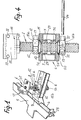
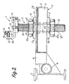
- the clamp device comprises a clamping jaw 1 fixed to the upper end of a vertical member 2 adjustable in height and movable horizontally on a support arm 6 fixed by its end to an eccentric 4 in a manner known per se, this eccentric itself being supported at its ends by a longitudinal beam 5 of the control bench.
- the vertical member 2 is a screw of suitable length and diameter, passing through two shims 5a, 5b, as well as a horizontal slide 6 forming the support arm.
- the wedge 5a of rectangular outline in the example described, is arranged on the slide 6, while the wedge 5b is placed under the latter, coaxially with the screw 2 like the wedge 5a.
- the slide 6 consists of two elongated bars 7, of rectangular section, distant from each other by a sufficient distance to allow the passage of the screw 2, and joined at their ends by means of transverse pieces 8, 9 welded to the bars 7.
- the wedges 5a, 5b are tightened against the bars 6 by respective nuts 11a, 11 coaxial with the screw 2.
- the nuts 11a, 11b are each provided with bosses 12 (three in number in the example illustrated in the drawings) pierced with holes 13 adapted to receive a maneuvering pin 14.
- the shims 5a, 5b are provided with bronze rings 10 coaxial with the screw 2, embedded in housings of the shims 5a, 5b and on which the corresponding centering cones 15 of the nuts 11a, 11b are supported.
- the actual clamp 1 placed at the upper end of the screw 2 is formed by the combination of an angle 16 fixed by its horizontal wing on a flange 17 welded to the upper end of the screw 2, and d 'a movable jaw 18 supported by the vertical wing 19 of the angle iron 16.
- the latter is fixed to the sole 17 by two bolts 21, while the jaw 18 is constituted by a U-shaped part, crossed by horizontal bolts 22 being screwed into the vertical wing 19, helical springs 23 being mounted coaxially to the bolts 22, between the wing 19 and the part 18.
- the upper end 24 of the jaw 18 is positioned opposite a heel 25 secured to the upper end of the wing 19, the bodywork (not shown) being placed between the heel 25 and the upper end 24.
- the clamp 1 thus produced is therefore removable, by simple removal of the bolts 21.
- the invention provides for placing millimeter scales 26, 27 respectively along the upper part of the screw 2, and along the horizontal slide 6.
- the vertical scale 26 makes it possible to adjust the position of the clamp 1 by rotation of the screw 2 in the shims 5a, 5b to the exact desired coordinate, while the horizontal scale 27 allows precise positioning, the screw 2 and the clamp 1 in the horizontal direction.
- the assembly formed by the actual clamp 1, the screw 2, the shims 5a, 5b and the locking nuts 11 a, 11 is moved manually by sliding the shims 5a, 5b on the horizontal bars 7, after loosening the nuts 11a, 11b.
- the screw 2 is at the desired location, read on the millimeter strip 27, the screw 2 and the clamp 1 are positioned vertically up to the chosen coordinate, read on the vertical strip 26. After which, the operator blocks the assembly in position by means of the pin 14 which it introduces into the bosses 12 of the nuts 11 a, 11 b.
- the pin 14 can also be used to block the clamp device against the marble with the eccentric 4.
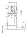
- the latter can also be operated in a manner known per se by a key 28 ( Figure 3).
- each wedge 5a, 5b is provided with a respective flange 29, 31 which projects inside the space between the bars 7, and thereby ensures the centering of the corresponding wedge 5a, 5b on slide 6.
- millimeter graduated strips 26, 27 advantageously allows precise adjustment of the position of the clamp 1 in the two vertical and horizontal coordinates, which was not possible with the previous embodiments.
- the clamp 1 support device has a resistance to bending in all directions, considerably increased compared to the previous embodiment mentioned above, thanks to the particular structure provided, in particular the slide 6 formed of the two arms horizontal 7 very rigid.
- the removable mounting of the angle 16 of the clamp 1 on the sole 17 has the advantage of allowing rapid exchange of the angle with another, more suitable for the body to be checked or straightened. This possibility of rapid replacement of the clamp with another is important, because it makes it possible to adapt the clamp device to the future development of bodywork.
- the invention is not limited to the embodiment described and may include alternative embodiments.
- the shims 5a, 5b could have a circular contour, as well as the locking nuts, which then would no longer include bosses for the introduction of the operating spindle.
- the slide 6 can be modified to take account of the possible development of the rocker panels (one-piece construction without sheet metal recovery, with removal of the rocker panel lips).
Claims (7)
Priority Applications (1)
| Application Number | Priority Date | Filing Date | Title |
|---|---|---|---|
| AT82401404T ATE17555T1 (de) | 1981-08-13 | 1982-07-28 | Klemmeinrichtung bestimmt zur montage an einer grundplatte oder bettung fuer die pruefung der etwaigen verformungen des aufbaues eines fahrzeuges. |
Applications Claiming Priority (2)
| Application Number | Priority Date | Filing Date | Title |
|---|---|---|---|
| FR8115672 | 1981-08-13 | ||
| FR8115672A FR2511501B1 (fr) | 1981-08-13 | 1981-08-13 | Dispositif de pince destine a etre monte sur un marbre ou banc de controle des deformations eventuelles de la carrosserie d'un vehicule |
Publications (3)
| Publication Number | Publication Date |
|---|---|
| EP0072725A1 EP0072725A1 (de) | 1983-02-23 |
| EP0072725B1 true EP0072725B1 (de) | 1986-01-22 |
| EP0072725B2 EP0072725B2 (de) | 1991-08-21 |
Family
ID=9261449
Family Applications (1)
| Application Number | Title | Priority Date | Filing Date |
|---|---|---|---|
| EP82401404A Expired - Lifetime EP0072725B2 (de) | 1981-08-13 | 1982-07-28 | Klemmeinrichtung bestimmt zur Montage an einer Grundplatte oder Bettung für die Prüfung der etwaigen Verformungen des Aufbaues eines Fahrzeuges |
Country Status (6)
| Country | Link |
|---|---|
| US (1) | US4519236A (de) |
| EP (1) | EP0072725B2 (de) |
| AT (1) | ATE17555T1 (de) |
| DE (1) | DE3268666D1 (de) |
| ES (1) | ES275447Y (de) |
| FR (1) | FR2511501B1 (de) |
Families Citing this family (28)
| Publication number | Priority date | Publication date | Assignee | Title |
|---|---|---|---|---|
| IT1107051B (it) * | 1983-02-28 | 1985-11-18 | Car Bench Spa | Banco per la riparazione di scoddhe di autoveicoli provvisto di supporti unificati per dime dotati di tre gradi di liberta' di movimento |
| US4586359A (en) * | 1983-10-31 | 1986-05-06 | Parks Thomas K | Anchor element positioner apparatus for automobile body repair and realignment |
| GB8329695D0 (en) * | 1983-11-07 | 1983-12-07 | Von Dulong O | Table/desk |
| SE449570B (sv) * | 1985-09-16 | 1987-05-11 | Samefa Ab | Karossklamma |
| FR2591328B1 (fr) * | 1985-12-06 | 1990-06-01 | Renault | Plate-forme de controle et/ou de reparation des carrosseries et chassis de vehicules automobiles |
| US4823589A (en) * | 1986-10-10 | 1989-04-25 | Whitney Equipment Sales, Inc. | Automotive frame straightening apparatus and method |
| US4916930A (en) * | 1987-11-16 | 1990-04-17 | Belgarde Richard J | Apparatus for realigning vehicle body and frame members |
| FR2657956B2 (fr) * | 1988-01-12 | 1994-09-30 | Deleuze Jean Michel | Instrument de controle et de mesure des caisses de vehicules par poutres, reglets et piges suspendues. |
| FR2625803B1 (fr) * | 1988-01-12 | 1994-08-12 | Deleuze Jean Michel | Instrument de controle et de mesure des caisses de vehicules par poutre, reglets et piges suspendues |
| FR2651165A1 (fr) * | 1989-08-31 | 1991-03-01 | Celette Sa | Dispositif a pince pour le serrage du bas de caisse d'un vehicule automobile. |
| US5044191A (en) * | 1990-03-21 | 1991-09-03 | Combs Paul D | Frame pulling bar and tool system |
| FR2666525A1 (fr) * | 1990-09-10 | 1992-03-13 | Celette Sa | Dispositif de montage d'une pince pour la tenue du bas de caisse d'un vehicule sur un marbre destine a la reparation de la carrosserie de ce vehicule. |
| FR2681539A1 (fr) * | 1991-09-19 | 1993-03-26 | Moussa Ismail | Systeme de fixation de vehicule a chassis sur banc de redressage. |
| US5413303A (en) * | 1993-12-16 | 1995-05-09 | Lee; Shih-Chiang | Supporting assembly for a vehicle chassis |
| US6182493B1 (en) * | 1995-03-10 | 2001-02-06 | Quick Stick, Inc. | Dual clamping adapter and vehicle repairing device |
| FI108338B (fi) * | 1999-11-26 | 2002-01-15 | Autorobot Finland | Menetelmõ ja laitteisto autonkorin oikaisuty÷ssõ ajoneuvon mittaamisessa ja menetelmõõ kõyttõvõ autonkorin mittakortti |
| US6185982B1 (en) * | 1999-12-01 | 2001-02-13 | Hein Werner Corporation | Apparatus for securing vehicle |
| US6568237B1 (en) | 2000-08-08 | 2003-05-27 | Hein-Werner Corporation | Apparatus and method for vehicle manipulative anchoring |
| DE10157649A1 (de) * | 2001-11-26 | 2003-06-05 | Junker & Partner Gmbh | Halteelement |
| US20040099039A1 (en) * | 2002-11-21 | 2004-05-27 | Michael Marx | Deck leverage anchor |
| WO2005051733A2 (en) * | 2003-11-21 | 2005-06-09 | Michael Marx | Deck leverage anchor with swivel mechanism |
| US7017384B2 (en) * | 2003-12-02 | 2006-03-28 | Michael Espinosa | Vehicle frame straightening jig |
| FI117892B (fi) * | 2004-12-07 | 2007-04-13 | Autorobot Finland | Kiinnitin autonkorin oikaisulaitteeseen |
| US9162271B2 (en) * | 2010-10-08 | 2015-10-20 | Michael J. Marx | Deck leverage anchor with spaced-apart body portions |
| US9085910B2 (en) * | 2011-07-11 | 2015-07-21 | Historic Plaster Conservation Products Limited | Plaster ceiling support device |
| US20160046001A1 (en) * | 2014-08-14 | 2016-02-18 | Kreg Enterprises, Inc. | Expandable locking mechanism and method of use |
| US20230347398A1 (en) * | 2019-04-14 | 2023-11-02 | Mark Jackson | Automobile dent puller apparatus |
| CN110864604A (zh) * | 2019-12-03 | 2020-03-06 | 徐晃 | 一种柴油发动机检测方法及装置 |
Family Cites Families (23)
| Publication number | Priority date | Publication date | Assignee | Title |
|---|---|---|---|---|
| US2563527A (en) * | 1951-08-07 | Or truing apparatus | ||
| US278094A (en) * | 1883-05-22 | Micro meter-gage | ||
| BE552071A (de) * | ||||
| US523284A (en) * | 1894-07-17 | Bonding joint for electric railways | ||
| US837267A (en) * | 1906-02-15 | 1906-11-27 | George M Bassett | Shaft-straightener for lathes. |
| US1083471A (en) * | 1912-10-15 | 1914-01-06 | Harry H Walton | Nut and bolt lock. |
| US1879979A (en) * | 1930-01-16 | 1932-09-27 | Guy A Countryman | Frame straightening tool |
| US2028354A (en) * | 1933-09-05 | 1936-01-21 | Nat Machinery Co | Adjustable die holder |
| US2232686A (en) * | 1938-04-27 | 1941-02-25 | Joseph Pavelka | Rail bender |
| US2219191A (en) * | 1939-04-10 | 1940-10-22 | Marcellus S Merrill | Press for automotive vehicle housings and associated parts |
| US2340587A (en) * | 1941-01-31 | 1944-02-01 | Hinckley Myers Company | Automobile straightening apparatus |
| US2493620A (en) * | 1948-01-28 | 1950-01-03 | Cusano Paul | Board leveling mechanism |
| US2684222A (en) * | 1952-05-02 | 1954-07-20 | Charles M Miller | Adjustable pipe support |
| US3172634A (en) * | 1963-02-01 | 1965-03-09 | Superior Scaffold Co | Adjustable shoring bracket |
| US3425473A (en) * | 1966-10-25 | 1969-02-04 | United Carr Inc | Washer-nut combination having a frangible connecting element |
| US3826459A (en) * | 1972-05-03 | 1974-07-30 | W Warren | Adjustable form support bracket |
| US3900179A (en) * | 1973-01-12 | 1975-08-19 | Waco Scaffold & Shoring Co | Column roll out support |
| SE414127B (sv) * | 1974-02-20 | 1980-07-14 | Nike Hydraulik Ab | Riktbenk for fordonskarosserier och -ramar |
| FR2384229A1 (fr) * | 1977-03-16 | 1978-10-13 | Olsson Erik Allan | Procede pour la mesure de cadres ou chassis de vehicules et dispositif pour l'application de ce procede |
| DE2745807A1 (de) * | 1977-10-12 | 1979-04-19 | Celette Gmbh | Universalverankerung fuer karosserien von kraftfahrzeugen |
| FR2423748A1 (fr) * | 1978-04-21 | 1979-11-16 | Celette Sa | Appareillage pour le controle des deformations d'une carrosserie de vehicule |
| FR2502994A1 (fr) * | 1981-04-01 | 1982-10-08 | Aerospatiale | Procede et dispositif de reglage automatique des poussoirs d'une presse d'emboutissage au moyen de verins a tige autobloquante |
| EP0104164A1 (de) * | 1982-03-30 | 1984-04-04 | Nicator Aktiebolag | Verfahren und vorrichtung zum ausrichten eines verformten elementes eines fahrzeuggestelles |
-
1981
- 1981-08-13 FR FR8115672A patent/FR2511501B1/fr not_active Expired
-
1982
- 1982-07-28 EP EP82401404A patent/EP0072725B2/de not_active Expired - Lifetime
- 1982-07-28 DE DE8282401404T patent/DE3268666D1/de not_active Expired
- 1982-07-28 AT AT82401404T patent/ATE17555T1/de not_active IP Right Cessation
- 1982-08-12 ES ES1982275447U patent/ES275447Y/es not_active Expired
-
1984
- 1984-09-10 US US06/649,163 patent/US4519236A/en not_active Expired - Fee Related
Also Published As
| Publication number | Publication date |
|---|---|
| DE3268666D1 (en) | 1986-03-06 |
| FR2511501A1 (fr) | 1983-02-18 |
| ES275447U (es) | 1984-08-01 |
| EP0072725B2 (de) | 1991-08-21 |
| FR2511501B1 (fr) | 1986-11-21 |
| ATE17555T1 (de) | 1986-02-15 |
| US4519236A (en) | 1985-05-28 |
| ES275447Y (es) | 1985-03-16 |
| EP0072725A1 (de) | 1983-02-23 |
Similar Documents
| Publication | Publication Date | Title |
|---|---|---|
| EP0072725B1 (de) | Klemmeinrichtung bestimmt zur Montage an einer Grundplatte oder Bettung für die Prüfung der etwaigen Verformungen des Aufbaues eines Fahrzeuges | |
| US4238951A (en) | Portable automobile straightening device | |
| FR2616095A1 (fr) | Procede et appareil pour etablir la position d'une reference de donnees d'apres un objet dont les variations dimensionnelles se trouvent a l'interieur d'une fourchette de tolerance | |
| FR2750063A1 (fr) | Pinces pour l'assemblage de produits metallurgiques plats | |
| EP0734338B1 (de) | Einrichtung zur befestigung eines rades eines motorrades am ständer und leistungsprüfstand dafür | |
| FR2544070A1 (fr) | Appareillage pour le montage d'une carrosserie de voiture sur un marbre de controle | |
| FR2578457A1 (fr) | Machine de traction pour le dressage et la relaxation des contraintes des rails en acier | |
| EP0453533B1 (de) | Numerisch gesteuerte maschine zum bearbeiten oder messen mit einer befestigungsvorrichtung für ein werkstück auf einem werktisch | |
| EP0018868A1 (de) | Vorrichtung zum in der Längsrichtung Schneiden von Brammen mittels Sauerstoffbrennschneiden | |
| FR3010688A1 (fr) | Outil permettant de remplacer le capot avant d'un vehicule automobile par un nouveau capot | |
| FR2652050A1 (fr) | Dispositif de fixation d'un vehicule et de reglage de sa position sur un chassis en vue de sa reparation. | |
| FR2722881A1 (fr) | Dispositif de prehension pour la realisation d'essais de traction a haute temperature sur des eprouvettes plates en materiau fragile | |
| EP0475860A1 (de) | Vorrichtung zum Befestigen einer Klemmeinrichtung zum Festhalten des Unterteils eines Fahrzeugs auf einer Richtbank zur Reparierung von Fahrzeugkarrosserien | |
| EP0104164A1 (de) | Verfahren und vorrichtung zum ausrichten eines verformten elementes eines fahrzeuggestelles | |
| FR2691652A1 (fr) | Perfectionnement aux dispositifs de fixation des outils sur presse-plieuse. | |
| EP0437413B1 (de) | Verschiebbare einheitliche Struktur zur Befestigung oder zum Unterstützen von Fahrzeugrädern | |
| BE899973A (fr) | Appareil pour la mesure, le calibrage et la remise en forme de vehicules accidentes. | |
| EP0100782B1 (de) | Werkstückhaltevorrichtung für Funkenerosionsmaschine mit Drahtelektrode | |
| FR2574877A1 (fr) | Dispositif de fixation et son procede de montage | |
| FR2591328A1 (fr) | Plate-forme de controle et/ou de reparation des carrosseries et chassis de vehicules automobiles | |
| FR2729879A1 (fr) | Procede et appareil pour le soudage par points en vue de l'assemblage d'un caisson de poutre d'une grue | |
| FR2651165A1 (fr) | Dispositif a pince pour le serrage du bas de caisse d'un vehicule automobile. | |
| BE1010498A6 (fr) | Dispositif pour le positionnement de pieces par rapport a un mandrin. | |
| FR2755638A1 (fr) | Machine de soudage de feuilles ou films en matiere synthetique | |
| FR2492091A1 (fr) | Banc ou marbre de controle et de redressage pour vehicules de tourisme et utilitaire |
Legal Events
| Date | Code | Title | Description |
|---|---|---|---|
| PUAI | Public reference made under article 153(3) epc to a published international application that has entered the european phase |
Free format text: ORIGINAL CODE: 0009012 |
|
| AK | Designated contracting states |
Designated state(s): AT BE CH DE GB IT LI NL SE |
|
| ITCL | It: translation for ep claims filed |
Representative=s name: CALVANI SALVI VERONELLI |
|
| 17P | Request for examination filed |
Effective date: 19830521 |
|
| GRAA | (expected) grant |
Free format text: ORIGINAL CODE: 0009210 |
|
| AK | Designated contracting states |
Designated state(s): AT BE CH DE GB IT LI NL SE |
|
| PG25 | Lapsed in a contracting state [announced via postgrant information from national office to epo] |
Ref country code: NL Effective date: 19860122 Ref country code: IT Free format text: LAPSE BECAUSE OF FAILURE TO SUBMIT A TRANSLATION OF THE DESCRIPTION OR TO PAY THE FEE WITHIN THE PRESCRIBED TIME-LIMIT;WARNING: LAPSES OF ITALIAN PATENTS WITH EFFECTIVE DATE BEFORE 2007 MAY HAVE OCCURRED AT ANY TIME BEFORE 2007. THE CORRECT EFFECTIVE DATE MAY BE DIFFERENT FROM THE ONE RECORDED. Effective date: 19860122 Ref country code: AT Effective date: 19860122 |
|
| REF | Corresponds to: |
Ref document number: 17555 Country of ref document: AT Date of ref document: 19860215 Kind code of ref document: T |
|
| REF | Corresponds to: |
Ref document number: 3268666 Country of ref document: DE Date of ref document: 19860306 |
|
| NLV1 | Nl: lapsed or annulled due to failure to fulfill the requirements of art. 29p and 29m of the patents act | ||
| PLBI | Opposition filed |
Free format text: ORIGINAL CODE: 0009260 |
|
| 26 | Opposition filed |
Opponent name: AKTIEBOLAGET SAMEFA Effective date: 19860808 |
|
| PLBI | Opposition filed |
Free format text: ORIGINAL CODE: 0009260 |
|
| 26 | Opposition filed |
Opponent name: BLACKHAWK GMBH Effective date: 19861022 |
|
| PGFP | Annual fee paid to national office [announced via postgrant information from national office to epo] |
Ref country code: CH Payment date: 19890928 Year of fee payment: 8 |
|
| PG25 | Lapsed in a contracting state [announced via postgrant information from national office to epo] |
Ref country code: LI Effective date: 19900731 Ref country code: CH Effective date: 19900731 |
|
| REG | Reference to a national code |
Ref country code: CH Ref legal event code: PL |
|
| PGFP | Annual fee paid to national office [announced via postgrant information from national office to epo] |
Ref country code: GB Payment date: 19910530 Year of fee payment: 10 |
|
| PGFP | Annual fee paid to national office [announced via postgrant information from national office to epo] |
Ref country code: DE Payment date: 19910607 Year of fee payment: 10 |
|
| PGFP | Annual fee paid to national office [announced via postgrant information from national office to epo] |
Ref country code: BE Payment date: 19910619 Year of fee payment: 10 |
|
| PUAH | Patent maintained in amended form |
Free format text: ORIGINAL CODE: 0009272 |
|
| STAA | Information on the status of an ep patent application or granted ep patent |
Free format text: STATUS: PATENT MAINTAINED AS AMENDED |
|
| PGFP | Annual fee paid to national office [announced via postgrant information from national office to epo] |
Ref country code: SE Payment date: 19910717 Year of fee payment: 10 |
|
| 27A | Patent maintained in amended form |
Effective date: 19910821 |
|
| AK | Designated contracting states |
Kind code of ref document: B2 Designated state(s): AT BE CH DE GB IT LI NL SE |
|
| PG25 | Lapsed in a contracting state [announced via postgrant information from national office to epo] |
Ref country code: GB Effective date: 19920728 |
|
| PG25 | Lapsed in a contracting state [announced via postgrant information from national office to epo] |
Ref country code: SE Effective date: 19920729 |
|
| PG25 | Lapsed in a contracting state [announced via postgrant information from national office to epo] |
Ref country code: BE Effective date: 19920731 |
|
| BERE | Be: lapsed |
Owner name: S.A. CELETTE Effective date: 19920731 |
|
| GBPC | Gb: european patent ceased through non-payment of renewal fee |
Effective date: 19920728 |
|
| PG25 | Lapsed in a contracting state [announced via postgrant information from national office to epo] |
Ref country code: DE Effective date: 19930401 |
|
| EUG | Se: european patent has lapsed |
Ref document number: 82401404.7 Effective date: 19930204 |
|
| APAH | Appeal reference modified |
Free format text: ORIGINAL CODE: EPIDOSCREFNO |
|
| PLAB | Opposition data, opponent's data or that of the opponent's representative modified |
Free format text: ORIGINAL CODE: 0009299OPPO |