EP0072725B1 - Clamping device to be mounted on a plate or bed for checking possible deformations of a vehicle body - Google Patents
Clamping device to be mounted on a plate or bed for checking possible deformations of a vehicle body Download PDFInfo
- Publication number
- EP0072725B1 EP0072725B1 EP82401404A EP82401404A EP0072725B1 EP 0072725 B1 EP0072725 B1 EP 0072725B1 EP 82401404 A EP82401404 A EP 82401404A EP 82401404 A EP82401404 A EP 82401404A EP 0072725 B1 EP0072725 B1 EP 0072725B1
- Authority
- EP
- European Patent Office
- Prior art keywords
- screw
- horizontal
- clamp
- blocks
- slide
- Prior art date
- Legal status (The legal status is an assumption and is not a legal conclusion. Google has not performed a legal analysis and makes no representation as to the accuracy of the status listed.)
- Expired
Links
- 229910000746 Structural steel Inorganic materials 0.000 claims description 3
- KUNSUQLRTQLHQQ-UHFFFAOYSA-N copper tin Chemical group [Cu].[Sn] KUNSUQLRTQLHQQ-UHFFFAOYSA-N 0.000 claims description 3
- 238000006073 displacement reaction Methods 0.000 claims 1
- 230000037237 body shape Effects 0.000 abstract 1
- 239000004579 marble Substances 0.000 description 4
- 230000000903 blocking effect Effects 0.000 description 2
- 238000011084 recovery Methods 0.000 description 2
- 238000005452 bending Methods 0.000 description 1
- 238000010276 construction Methods 0.000 description 1
- 230000003100 immobilizing effect Effects 0.000 description 1
- 239000002184 metal Substances 0.000 description 1
- 229910052751 metal Inorganic materials 0.000 description 1
Images
Classifications
-
- B—PERFORMING OPERATIONS; TRANSPORTING
- B21—MECHANICAL METAL-WORKING WITHOUT ESSENTIALLY REMOVING MATERIAL; PUNCHING METAL
- B21D—WORKING OR PROCESSING OF SHEET METAL OR METAL TUBES, RODS OR PROFILES WITHOUT ESSENTIALLY REMOVING MATERIAL; PUNCHING METAL
- B21D1/00—Straightening, restoring form or removing local distortions of sheet metal or specific articles made therefrom; Stretching sheet metal combined with rolling
- B21D1/14—Straightening frame structures
-
- F—MECHANICAL ENGINEERING; LIGHTING; HEATING; WEAPONS; BLASTING
- F16—ENGINEERING ELEMENTS AND UNITS; GENERAL MEASURES FOR PRODUCING AND MAINTAINING EFFECTIVE FUNCTIONING OF MACHINES OR INSTALLATIONS; THERMAL INSULATION IN GENERAL
- F16B—DEVICES FOR FASTENING OR SECURING CONSTRUCTIONAL ELEMENTS OR MACHINE PARTS TOGETHER, e.g. NAILS, BOLTS, CIRCLIPS, CLAMPS, CLIPS OR WEDGES; JOINTS OR JOINTING
- F16B2/00—Friction-grip releasable fastenings
- F16B2/02—Clamps, i.e. with gripping action effected by positive means other than the inherent resistance to deformation of the material of the fastening
- F16B2/06—Clamps, i.e. with gripping action effected by positive means other than the inherent resistance to deformation of the material of the fastening external, i.e. with contracting action
- F16B2/12—Clamps, i.e. with gripping action effected by positive means other than the inherent resistance to deformation of the material of the fastening external, i.e. with contracting action using sliding jaws
-
- F—MECHANICAL ENGINEERING; LIGHTING; HEATING; WEAPONS; BLASTING
- F16—ENGINEERING ELEMENTS AND UNITS; GENERAL MEASURES FOR PRODUCING AND MAINTAINING EFFECTIVE FUNCTIONING OF MACHINES OR INSTALLATIONS; THERMAL INSULATION IN GENERAL
- F16B—DEVICES FOR FASTENING OR SECURING CONSTRUCTIONAL ELEMENTS OR MACHINE PARTS TOGETHER, e.g. NAILS, BOLTS, CIRCLIPS, CLAMPS, CLIPS OR WEDGES; JOINTS OR JOINTING
- F16B7/00—Connections of rods or tubes, e.g. of non-circular section, mutually, including resilient connections
- F16B7/04—Clamping or clipping connections
- F16B7/044—Clamping or clipping connections for rods or tubes being in angled relationship
- F16B7/048—Clamping or clipping connections for rods or tubes being in angled relationship for rods or for tubes without using the innerside thereof
-
- G—PHYSICS
- G01—MEASURING; TESTING
- G01B—MEASURING LENGTH, THICKNESS OR SIMILAR LINEAR DIMENSIONS; MEASURING ANGLES; MEASURING AREAS; MEASURING IRREGULARITIES OF SURFACES OR CONTOURS
- G01B5/00—Measuring arrangements characterised by the use of mechanical techniques
- G01B5/0025—Measuring of vehicle parts
-
- Y—GENERAL TAGGING OF NEW TECHNOLOGICAL DEVELOPMENTS; GENERAL TAGGING OF CROSS-SECTIONAL TECHNOLOGIES SPANNING OVER SEVERAL SECTIONS OF THE IPC; TECHNICAL SUBJECTS COVERED BY FORMER USPC CROSS-REFERENCE ART COLLECTIONS [XRACs] AND DIGESTS
- Y10—TECHNICAL SUBJECTS COVERED BY FORMER USPC
- Y10S—TECHNICAL SUBJECTS COVERED BY FORMER USPC CROSS-REFERENCE ART COLLECTIONS [XRACs] AND DIGESTS
- Y10S72/00—Metal deforming
- Y10S72/705—Vehicle body or frame straightener
Definitions
- the present invention relates to a clamp device, intended to be mounted on a marble or bench for checking possible deformations of the body of a vehicle, in order to keep the body immobilized during the control and straightening operations of the latter. .
- the clamp devices which ensure the tightening of the underbody lips each consist of a vertical bar carrying at its upper end the clamp itself, a clamp inside which the bar is movable vertically, and a horizontal arm on which the collar is slidably mounted.
- the horizontal bar is attached along the associated lateral beam of the control bench, and fixed by its end to this beam.
- the object of the invention is to remedy these drawbacks by producing a clamp device allowing very precise adjustment and blocking in the vertical and horizontal directions, and the flexural strength of which is considerably reinforced, the operation of this clamp being in further simplified to the maximum.
- FR-A-2 423 748 which already describes a clamp device intended to be mounted on a plate or bench for checking possible deformations of the body of a vehicle, in order to keep the body immobilized during the control operations and straightening the latter, comprising a clamp (1) mounted on a vertical support member (2) adjustable in height and movable laterally on a horizontal support arm (6), the vertical support member of a on the one hand and the horizontal support arm on the other hand comprising blocking means (11a, 11b) for immobilizing the clamp (1) in a determined precise vertical and horizontal position
- the invention is characterized in that the support member vertical of the clamp (1) is constituted by a screw (2) passing through shims (5a, 5b) disposed respectively on and under the horizontal support arm constituted by a slide (6), these shims cooperating with nuts (11a, 11b) for real estate sation of the screw on the slide in a selected position in the horizontal and vertical directions.
- the horizontal slide preferably being made up of two very robust bars, spaced apart by an interval allowing the passage of the screw and secured by their ends, this arrangement provides a device whose flexural strength is significantly increased compared to to that of the aforementioned anterior clamp.
- the wedges are tightened against the bars by nuts, preferably provided with hollow bosses adapted to receive an operating pin.
- millimeter scales are placed along the horizontal slide and on the screw, in order to allow precise adjustment of the position of the clamp in the vertical and horizontal coordinates.
- the clamp device shown in the drawings is intended to be mounted on a marble or bench for checking possible deformations of the body of a vehicle, such as that described in the aforementioned French patent, in order to keep the body immobilized during the control operations. and recovery of the latter.
- the clamp device comprises a clamping jaw 1 fixed to the upper end of a vertical member 2 adjustable in height and movable horizontally on a support arm 6 fixed by its end to an eccentric 4 in a manner known per se, this eccentric itself being supported at its ends by a longitudinal beam 5 of the control bench.
- the vertical member 2 is a screw of suitable length and diameter, passing through two shims 5a, 5b, as well as a horizontal slide 6 forming the support arm.
- the wedge 5a of rectangular outline in the example described, is arranged on the slide 6, while the wedge 5b is placed under the latter, coaxially with the screw 2 like the wedge 5a.
- the slide 6 consists of two elongated bars 7, of rectangular section, distant from each other by a sufficient distance to allow the passage of the screw 2, and joined at their ends by means of transverse pieces 8, 9 welded to the bars 7.
- the wedges 5a, 5b are tightened against the bars 6 by respective nuts 11a, 11 coaxial with the screw 2.
- the nuts 11a, 11b are each provided with bosses 12 (three in number in the example illustrated in the drawings) pierced with holes 13 adapted to receive a maneuvering pin 14.
- the shims 5a, 5b are provided with bronze rings 10 coaxial with the screw 2, embedded in housings of the shims 5a, 5b and on which the corresponding centering cones 15 of the nuts 11a, 11b are supported.
- the actual clamp 1 placed at the upper end of the screw 2 is formed by the combination of an angle 16 fixed by its horizontal wing on a flange 17 welded to the upper end of the screw 2, and d 'a movable jaw 18 supported by the vertical wing 19 of the angle iron 16.
- the latter is fixed to the sole 17 by two bolts 21, while the jaw 18 is constituted by a U-shaped part, crossed by horizontal bolts 22 being screwed into the vertical wing 19, helical springs 23 being mounted coaxially to the bolts 22, between the wing 19 and the part 18.
- the upper end 24 of the jaw 18 is positioned opposite a heel 25 secured to the upper end of the wing 19, the bodywork (not shown) being placed between the heel 25 and the upper end 24.
- the clamp 1 thus produced is therefore removable, by simple removal of the bolts 21.
- the invention provides for placing millimeter scales 26, 27 respectively along the upper part of the screw 2, and along the horizontal slide 6.
- the vertical scale 26 makes it possible to adjust the position of the clamp 1 by rotation of the screw 2 in the shims 5a, 5b to the exact desired coordinate, while the horizontal scale 27 allows precise positioning, the screw 2 and the clamp 1 in the horizontal direction.
- the assembly formed by the actual clamp 1, the screw 2, the shims 5a, 5b and the locking nuts 11 a, 11 is moved manually by sliding the shims 5a, 5b on the horizontal bars 7, after loosening the nuts 11a, 11b.
- the screw 2 is at the desired location, read on the millimeter strip 27, the screw 2 and the clamp 1 are positioned vertically up to the chosen coordinate, read on the vertical strip 26. After which, the operator blocks the assembly in position by means of the pin 14 which it introduces into the bosses 12 of the nuts 11 a, 11 b.
- the pin 14 can also be used to block the clamp device against the marble with the eccentric 4.
- the latter can also be operated in a manner known per se by a key 28 ( Figure 3).
- each wedge 5a, 5b is provided with a respective flange 29, 31 which projects inside the space between the bars 7, and thereby ensures the centering of the corresponding wedge 5a, 5b on slide 6.
- millimeter graduated strips 26, 27 advantageously allows precise adjustment of the position of the clamp 1 in the two vertical and horizontal coordinates, which was not possible with the previous embodiments.
- the clamp 1 support device has a resistance to bending in all directions, considerably increased compared to the previous embodiment mentioned above, thanks to the particular structure provided, in particular the slide 6 formed of the two arms horizontal 7 very rigid.
- the removable mounting of the angle 16 of the clamp 1 on the sole 17 has the advantage of allowing rapid exchange of the angle with another, more suitable for the body to be checked or straightened. This possibility of rapid replacement of the clamp with another is important, because it makes it possible to adapt the clamp device to the future development of bodywork.
- the invention is not limited to the embodiment described and may include alternative embodiments.
- the shims 5a, 5b could have a circular contour, as well as the locking nuts, which then would no longer include bosses for the introduction of the operating spindle.
- the slide 6 can be modified to take account of the possible development of the rocker panels (one-piece construction without sheet metal recovery, with removal of the rocker panel lips).
Landscapes
- Engineering & Computer Science (AREA)
- General Engineering & Computer Science (AREA)
- Mechanical Engineering (AREA)
- Physics & Mathematics (AREA)
- General Physics & Mathematics (AREA)
- Clamps And Clips (AREA)
- Vehicle Cleaning, Maintenance, Repair, Refitting, And Outriggers (AREA)
- Jigs For Machine Tools (AREA)
- Load-Engaging Elements For Cranes (AREA)
- Connection Of Plates (AREA)
- Automobile Manufacture Line, Endless Track Vehicle, Trailer (AREA)
- Forklifts And Lifting Vehicles (AREA)
- Supports For Pipes And Cables (AREA)
- Body Structure For Vehicles (AREA)
- Length Measuring Devices By Optical Means (AREA)
- Lighting Device Outwards From Vehicle And Optical Signal (AREA)
Abstract
Description
La présente invention a pour objet un dispositif de pince, destiné à être monté sur un marbre ou banc de contrôle des déformations éventuelles de la carrosserie d'un véhicule, afin de maintenir la carrosserie immobilisée pendant les opérations de contrôle et de redressement de cette dernière.The present invention relates to a clamp device, intended to be mounted on a marble or bench for checking possible deformations of the body of a vehicle, in order to keep the body immobilized during the control and straightening operations of the latter. .
Comme on le sait, le contrôle des déformations d'une carrosserie de véhicule ou la réparation d'une carrosserie accidentée sont exécutés sur un banc ou marbre de contrôle tel que celui décrit dans le brevet français FR-A-2 423 748, qui est équipé d'un ensemble de ferrures et de dispositifs de pinces permettant d'immobiliser en place le véhicule pendant les opérations.As is known, the control of the deformations of a vehicle bodywork or the repair of an accidental bodywork are carried out on a test bench or marble such as that described in French patent FR-A-2,423,748, which is equipped with a set of fittings and clamp devices to immobilize the vehicle in place during operations.
Dans ce mode de réalisation connu, les dispositifs de pinces qui assurent le serrage des lèvres du bas de caisse, sont chacun constitués d'un barreau vertical portant à son extrémité supérieure la pince proprement dite, d'un collier de serrage à l'intérieur duquel le barreau est mobile verticalement, et d'un bras horizontal sur lequel le collier est monté coulissant. Le barreau horizontal est rapporté le long de la poutre latérale associée du banc de contrôle, et fixé par son extrémité sur cette poutre.In this known embodiment, the clamp devices which ensure the tightening of the underbody lips, each consist of a vertical bar carrying at its upper end the clamp itself, a clamp inside which the bar is movable vertically, and a horizontal arm on which the collar is slidably mounted. The horizontal bar is attached along the associated lateral beam of the control bench, and fixed by its end to this beam.
Ce système permet de modifier la position des pinces dans différentes directions, afin de les placer correctement pour serrer les lèvres du bas de caisse. Cependant, la mise en oeuvre de ces systèmes de pinces est relativement peu commode, et le positionnement de la pince manque en pratique de précision. De plus, on constate que la résistance à la flexion de ces pinces, dans les diverses directions où elle est sollicitée, n'est pas toujours suffisante.This system allows you to change the position of the clamps in different directions, in order to place them correctly to tighten the lips of the rocker panel. However, the implementation of these gripper systems is relatively inconvenient, and the positioning of the gripper lacks precision in practice. In addition, it can be seen that the flexural strength of these clamps, in the various directions in which it is stressed, is not always sufficient.
L'invention a pour but de remédier à ces inconvénients en réalisant un dispositif de pince permettant un réglage très précis et un blocage dans les directions verticale et horizontale, et dont la résistance à la flexion soit considérablement renforcée, la manoeuvre de cette pince étant en outre simplifiée au maximum.The object of the invention is to remedy these drawbacks by producing a clamp device allowing very precise adjustment and blocking in the vertical and horizontal directions, and the flexural strength of which is considerably reinforced, the operation of this clamp being in further simplified to the maximum.
Par rapport au FR-A-2 423 748 qui décrit déjà un dispositif de pince destiné à être monté sur un marbre ou banc de contrôle des déformations éventuelles de la carrosserie d'un véhicule, afin de maintenir la carrosserie immobilisée pendant les opérations de contrôle et de redressement de cette dernière, comportant une pince de serrage (1) montée sur un organe de support vertical (2) réglable en hauteur et déplaçable latéralement sur un bras de support horizontal (6), l'organe de support vertical d'une part et le bras de support horizontal d'autre part comportant des moyens de blocage (11a, 11b) pour immobiliser la pince (1) dans une position verticale et horizontale précise déterminée, l'invention est caractérisée en ce que l'organe de support vertical de la pince (1) est constitué par une vis (2) traversant des cales (5a, 5b) disposées respectivement sur et sous le bras de support horizontal constitué par une glissière (6), ces cales coopérant avec des écrous (11a, 11b) pour l'immobilisation de la vis sur la glissière en une position choisie dans les directions horizontale et verticale.Compared to FR-A-2 423 748 which already describes a clamp device intended to be mounted on a plate or bench for checking possible deformations of the body of a vehicle, in order to keep the body immobilized during the control operations and straightening the latter, comprising a clamp (1) mounted on a vertical support member (2) adjustable in height and movable laterally on a horizontal support arm (6), the vertical support member of a on the one hand and the horizontal support arm on the other hand comprising blocking means (11a, 11b) for immobilizing the clamp (1) in a determined precise vertical and horizontal position, the invention is characterized in that the support member vertical of the clamp (1) is constituted by a screw (2) passing through shims (5a, 5b) disposed respectively on and under the horizontal support arm constituted by a slide (6), these shims cooperating with nuts (11a, 11b) for real estate sation of the screw on the slide in a selected position in the horizontal and vertical directions.
La glissière horizontale étant de préférence constituée de deux barreaux très robustes, distants entre eux d'un intervalle permettant le passage de la vis et solidarisés par leurs extrémités, on obtient par cet agencement un dispositif dont la résistance à la flexion est notablement augmentée par rapport à celle de la pince antérieure précitée.The horizontal slide preferably being made up of two very robust bars, spaced apart by an interval allowing the passage of the screw and secured by their ends, this arrangement provides a device whose flexural strength is significantly increased compared to to that of the aforementioned anterior clamp.
Suivant un mode de réalisation préféré, les cales sont serrées contre les barreaux par des écrous, pourvus de préférence de bossages creux adaptés pour recevoir une broche de manoeuvre.According to a preferred embodiment, the wedges are tightened against the bars by nuts, preferably provided with hollow bosses adapted to receive an operating pin.
Pour régler verticalement la position de la vis et de la pince portée par celle-ci, il suffit donc de desserrer les écrous, puis de faire tourner la vis jusqu'à ce qu'elle ait atteint la position voulue.To vertically adjust the position of the screw and the clamp carried by it, it is sufficient to loosen the nuts, then rotate the screw until it has reached the desired position.
Complémentairement, il suffit, pour disposer la vis et la pince dans le sens horizontal à l'emplacement choisi, de faire glisser les cales sur les barreaux de support. La pince est bloquée à la position choisie par simple serrage des écrous, qui bloquent les cales contre les barreaux de la glissière.In addition, it is sufficient to place the screw and the clamp in the horizontal direction at the chosen location, by sliding the shims onto the support bars. The clamp is locked in the chosen position by simply tightening the nuts, which block the shims against the bars of the slide.
Suivant une autre caractéristique de l'invention, des échelles millimétriques sont placées le long de la glissière horizontale et sur la vis, afin de permettre un réglage précis de la position de la pince dans les coordonnées verticale et horizontale.According to another characteristic of the invention, millimeter scales are placed along the horizontal slide and on the screw, in order to allow precise adjustment of the position of the clamp in the vertical and horizontal coordinates.
D'autres particularités et avantages de l'invention apparaîtront au cours de la description qui va suivre, faite en référence aux dessins annexés sur lesquels on a représenté à titre de l'exemple non limitatif, une forme de réalisation du dispositif de pince selon l'invention.
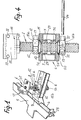
- La figure 1 est une vue en perspective d'un dispositif de pince selon l'invention.
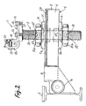
- La figure 2 est une vue en élévation longitudinale à échelle agrandie, du dispositif de pince de la figure 1 monté sur le côté d'un marbre de contrôle de la carrosserie d'un véhicule.
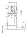
- La figure 3 est une vue de dessus en plan à la même échelle que la figure 2, du dispositif de pince des figures 1 et 2.
- La figure 4 est une vue mi-coupe transversale, mi-élévation du dispositif de pince des figures 1 à 3.
- Figure 1 is a perspective view of a clamp device according to the invention.
- Figure 2 is a longitudinal elevational view on an enlarged scale, of the clamp device of Figure 1 mounted on the side of a control panel of the body of a vehicle.
- FIG. 3 is a top plan view, on the same scale as FIG. 2, of the clamp device of FIGS. 1 and 2.
- FIG. 4 is a half-cross-sectional, half-elevation view of the clamp device of FIGS. 1 to 3.
Le dispositif de pince représenté aux dessins est destiné à être monté sur un marbre ou banc de contrôle des déformations éventuelles de la carrosserie d'un véhicule, tel que celui décrit au brevet français précité, afin de maintenir la carrosserie immobilisée pendant les opérations de contrôle et de redressement de cette dernière.The clamp device shown in the drawings is intended to be mounted on a marble or bench for checking possible deformations of the body of a vehicle, such as that described in the aforementioned French patent, in order to keep the body immobilized during the control operations. and recovery of the latter.
Le dispositif de pince comporte une mâchoire 1 de serrage fixée à l'extrémité supérieure d'un organe vertical 2 réglable en hauteur et déplaçable horizontalement sur un bras de support 6 fixé par son extrémité à un excentrique 4 de façon connue en soi, cet excentrique étant lui-même supporté à ses extrémités par une poutre longitudinale 5 du banc de contrôle.The clamp device comprises a
Suivant l'invention, l'organe vertical 2 est une vis de longueur et de diamètre convenables, traversant deux cales 5a, 5b, ainsi qu'une glissière horizontale 6 formant le bras de support. La cale 5a, de contour rectangulaire dans l'exemple décrit, est disposée sur la glissière 6, tandis que la cale 5b est placée sous celle-ci, coaxialement à la vis 2 comme la cale 5a.According to the invention, the
La glissière 6 est constituée de deux barreaux allongés 7, de section rectangulaire, distants entre eux d'un intervalle suffisant pour permettre le passage de la vis 2, et solidarisés par leurs extrémités au moyen de pièces transversales 8, 9 soudées aux barreaux 7. Les cales 5a, 5b sont serrées contre les barreaux 6 par des écrous respectifs 11 a, 11 coaxiaux à la vis 2.The
Les écrous 11a, 11b sont chacun pourvus de bossages 12 (au nombre de trois dans l'exemple illustré aux dessins) percés de trous 13 adaptés pour recevoir une broche 14 de manoeuvre. Les cales 5a, 5b sont pourvues de bagues 10 en bronze coaxiales à la vis 2, encastrées dans des logements des cales 5a, 5b et sur lesquelles prennent appui des cônes de centrage 15 correspondants des écrous 11 a, 11b.The
La pince de serrage proprement dite 1 placée à l'extrémité supérieure de la vis 2, est formée par la combinaison d'une cornière 16 fixée par son aile horizontale sur une semelle 17 soudée à l'extrémité supérieure de la vis 2, et d'une mâchoire mobile 18 supportée par l'aile verticale 19 de la cornière 16. Cette dernière est fixée à la semelle 17 par deux boulons 21, tandis que la mâchoire 18 est constituée par une pièce de section en U, traversée par des boulons horizontaux 22 venant se visser dans l'aile verticale 19, des ressorts hélicoïdaux 23 étant montés coaxialement aux boulons 22, entre l'aile 19 et la pièce 18. L'extrémité supérieure 24 de la mâchoire 18 est positionnée en regard d'un talon 25 solidaire de l'extrémité supérieure de l'aile 19, la carrosserie (non représentée) étant placée entre le talon 25 et l'extrémité supérieure 24.The
La pince 1 ainsi réalisée est donc amovible, et ce par simple enlèvement des boulons 21.The
Suivant une particularité, l'invention prévoit de placer des échelles millimétriques 26, 27 respectivement le long de la partie supérieure de la vis 2, et le long de la glissière horizontale 6. L'échelle verticale 26 permet de régler la position de la pince 1 par rotation de la vis 2 dans les cales 5a, 5b jusqu'à la coordonnée exacte voulue, tandis que l'échelle horizontale 27 permet de positionner de manière précise, la vis 2 et la pince 1 dans le sens horizontal.According to one feature, the invention provides for placing
La mise en oeuvre et les avantages techniques du dispositif de pince qui vient d'être décrit sont les suivants.The implementation and the technical advantages of the clamp device which has just been described are as follows.
L'ensemble formé par la pince proprement dite 1, la vis 2, les cales 5a, 5b et les écrous de blocage 11 a, 11 est déplacé manuellement en faisant glisser les cales 5a, 5b sur les barreaux horizontaux 7, après desserrage des écrous 11a, 11b. Lorsque la vis 2 est à l'emplacement voulu, lu sur la réglette millimétrée 27, on positionne la vis 2 et la pince 1 en hauteur jusqu'à la coordonnée choisie, lue sur la réglette verticale 26. Après quoi, l'opérateur bloque l'ensemble en position au moyen de la broche 14 qu'il introduit dans les bossages 12 des écrous 11 a, 11 b.The assembly formed by the
La rotation des écrous est favorisée par la présence des bagues de bronze 10 formant coussinets. Il ne reste plus ensuite à l'opérateur qu'à serrer la mâchoire 18 sur l'emplacement correspondant de la carrosserie, par actionnement des boulons 22.The rotation of the nuts is favored by the presence of the
Bien entendu, il est également possible de commencer par positionner en hauteur la pince 1 avant de la régler dans la direction horizontale.Of course, it is also possible to start by positioning the
Il convient de noter que la libération de l'écrou supérieur 11a, l'écrou inférieur 11b restant bloqué, permet un réglage en hauteur de la vis 2 et de la pince 1, et par conséquent un positionnement de cette dernière au mm près.It should be noted that the release of the
La broche 14 peut être utilisée également pour bloquer le dispositif de pince contre le marbre avec l'excentrique 4. Ce dernier peut aussi être manoeuvré de façon connue en soi par une clé 28 (figure 3).The
On remarquera (figure 4) que chaque cale 5a, 5b est munie d'une collerette respective 29, 31 qui fait saillie à l'intérieur de l'espace compris entre les barreaux 7, et assure de ce fait le centrage de la cale correspondante 5a, 5b sur la glissière 6.Note (Figure 4) that each
La présence des réglettes graduées millimétriques 26, 27 permet avantageusement un réglage précis de la position de la pince 1 dans les deux coordonnées verticale et horizontale, ce qui n'était pas possible avec les réalisations antérieures.The presence of the millimeter graduated
D'autre part, le dispositif de support de la pince 1 a une résistance à la flexion dans tous les sens, considérablement augmentée par rapport à la réalisation antérieure mentionnée précédemment, grâce à la structure particulière prévue, notamment la glissière 6 formée des deux bras horizontaux 7 très rigides.On the other hand, the
Enfin, le montage amovible de la cornière 16 de la pince 1 sur la semelle 17 présente l'avantage de permettre un échange rapide de la cornière avec une autre, plus adaptée à la carrosserie à contrôler ou à redresser. Cette possibilité de remplacement rapide de la pince par une autre est importante, car elle permet d'adapter le dispositif de pince à l'évolution future des carrosseries.Finally, the removable mounting of the
L'invention n'est pas limitée à la forme de réalisation décrite et peut comporter des variantes d'exécution. Ainsi les cales 5a, 5b pourraient avoir un contour circulaire, de même que les écrous de blocage, qui alors ne comporteraient plus de bossages pour l'introduction de la broche de manoeuvre. On notera d'autre part que la glissière 6 peut être modifiée pour tenir compte de l'évolution possible des bas de caisses (construction monobloc sans reprise de tôle, avec suppression des lèvres de bas de caisse).The invention is not limited to the embodiment described and may include alternative embodiments. Thus the
Claims (7)
Priority Applications (1)
| Application Number | Priority Date | Filing Date | Title |
|---|---|---|---|
| AT82401404T ATE17555T1 (en) | 1981-08-13 | 1982-07-28 | CLAMPING DEVICE INTENDED FOR MOUNTING ON A BASE PLATE OR BED FOR CHECKING THE POSSIBLE DEFORMATIONS OF THE BODYWORK OF A VEHICLE. |
Applications Claiming Priority (2)
| Application Number | Priority Date | Filing Date | Title |
|---|---|---|---|
| FR8115672 | 1981-08-13 | ||
| FR8115672A FR2511501B1 (en) | 1981-08-13 | 1981-08-13 | CLIP DEVICE FOR MOUNTING ON A MARBLE OR BENCH FOR MONITORING DEFORMATIONS OF THE BODY OF A VEHICLE |
Publications (3)
| Publication Number | Publication Date |
|---|---|
| EP0072725A1 EP0072725A1 (en) | 1983-02-23 |
| EP0072725B1 true EP0072725B1 (en) | 1986-01-22 |
| EP0072725B2 EP0072725B2 (en) | 1991-08-21 |
Family
ID=9261449
Family Applications (1)
| Application Number | Title | Priority Date | Filing Date |
|---|---|---|---|
| EP82401404A Expired - Lifetime EP0072725B2 (en) | 1981-08-13 | 1982-07-28 | Clamping device to be mounted on a plate or bed for checking possible deformations of a vehicle body |
Country Status (6)
| Country | Link |
|---|---|
| US (1) | US4519236A (en) |
| EP (1) | EP0072725B2 (en) |
| AT (1) | ATE17555T1 (en) |
| DE (1) | DE3268666D1 (en) |
| ES (1) | ES275447Y (en) |
| FR (1) | FR2511501B1 (en) |
Families Citing this family (28)
| Publication number | Priority date | Publication date | Assignee | Title |
|---|---|---|---|---|
| IT1107051B (en) * | 1983-02-28 | 1985-11-18 | Car Bench Spa | VEHICLE REPAIR BENCH PROVIDED WITH UNIFIED SUPPORTS FOR TEMPLATES EQUIPPED WITH THREE DEGREES OF FREEDOM OF MOVEMENT |
| US4586359A (en) * | 1983-10-31 | 1986-05-06 | Parks Thomas K | Anchor element positioner apparatus for automobile body repair and realignment |
| GB8329695D0 (en) * | 1983-11-07 | 1983-12-07 | Von Dulong O | Table/desk |
| SE449570B (en) * | 1985-09-16 | 1987-05-11 | Samefa Ab | KAROSSKLAMMA |
| FR2591328B1 (en) * | 1985-12-06 | 1990-06-01 | Renault | PLATFORM FOR CHECKING AND / OR REPAIRING BODIES AND CHASSIS OF MOTOR VEHICLES |
| US4823589A (en) * | 1986-10-10 | 1989-04-25 | Whitney Equipment Sales, Inc. | Automotive frame straightening apparatus and method |
| US4916930A (en) * | 1987-11-16 | 1990-04-17 | Belgarde Richard J | Apparatus for realigning vehicle body and frame members |
| FR2657956B2 (en) * | 1988-01-12 | 1994-09-30 | Deleuze Jean Michel | INSTRUMENT FOR MONITORING AND MEASURING THE BODIES OF VEHICLES BY BEAMS, RULES AND SUSPENDED RODS. |
| FR2625803B1 (en) * | 1988-01-12 | 1994-08-12 | Deleuze Jean Michel | INSTRUMENT FOR MONITORING AND MEASURING THE BODIES OF VEHICLES BY BEAM, RULES AND SUSPENDED RODS |
| FR2651165A1 (en) * | 1989-08-31 | 1991-03-01 | Celette Sa | Clamp device for clamping the bottom of a motor vehicle body |
| US5044191A (en) * | 1990-03-21 | 1991-09-03 | Combs Paul D | Frame pulling bar and tool system |
| FR2666525A1 (en) * | 1990-09-10 | 1992-03-13 | Celette Sa | DEVICE FOR MOUNTING A CLAMP FOR HOLDING THE BOTTOM OF A VEHICLE ON A MARBLE FOR REPAIRING THE BODY OF THE VEHICLE. |
| FR2681539A1 (en) * | 1991-09-19 | 1993-03-26 | Moussa Ismail | System for securing a chassis-type vehicle on a straightening bench |
| US5413303A (en) * | 1993-12-16 | 1995-05-09 | Lee; Shih-Chiang | Supporting assembly for a vehicle chassis |
| US6182493B1 (en) * | 1995-03-10 | 2001-02-06 | Quick Stick, Inc. | Dual clamping adapter and vehicle repairing device |
| FI108338B (en) * | 1999-11-26 | 2002-01-15 | Autorobot Finland | Procedure and installation for measuring a vehicle in the direction of a car body and a driving license for a car body utilizing the procedure |
| US6185982B1 (en) * | 1999-12-01 | 2001-02-13 | Hein Werner Corporation | Apparatus for securing vehicle |
| US6568237B1 (en) | 2000-08-08 | 2003-05-27 | Hein-Werner Corporation | Apparatus and method for vehicle manipulative anchoring |
| DE10157649A1 (en) * | 2001-11-26 | 2003-06-05 | Junker & Partner Gmbh | retaining element |
| US20040099039A1 (en) * | 2002-11-21 | 2004-05-27 | Michael Marx | Deck leverage anchor |
| WO2005051733A2 (en) * | 2003-11-21 | 2005-06-09 | Michael Marx | Deck leverage anchor with swivel mechanism |
| US7017384B2 (en) * | 2003-12-02 | 2006-03-28 | Michael Espinosa | Vehicle frame straightening jig |
| FI117892B (en) * | 2004-12-07 | 2007-04-13 | Autorobot Finland | Fastening device for straightening device of car body |
| US9162271B2 (en) * | 2010-10-08 | 2015-10-20 | Michael J. Marx | Deck leverage anchor with spaced-apart body portions |
| US9085910B2 (en) * | 2011-07-11 | 2015-07-21 | Historic Plaster Conservation Products Limited | Plaster ceiling support device |
| US20160046001A1 (en) * | 2014-08-14 | 2016-02-18 | Kreg Enterprises, Inc. | Expandable locking mechanism and method of use |
| US20230347398A1 (en) * | 2019-04-14 | 2023-11-02 | Mark Jackson | Automobile dent puller apparatus |
| CN110864604A (en) * | 2019-12-03 | 2020-03-06 | 徐晃 | Diesel engine detection method and device |
Family Cites Families (23)
| Publication number | Priority date | Publication date | Assignee | Title |
|---|---|---|---|---|
| BE552071A (en) * | ||||
| US2563527A (en) * | 1951-08-07 | Or truing apparatus | ||
| US278094A (en) * | 1883-05-22 | Micro meter-gage | ||
| US523284A (en) * | 1894-07-17 | Bonding joint for electric railways | ||
| US837267A (en) * | 1906-02-15 | 1906-11-27 | George M Bassett | Shaft-straightener for lathes. |
| US1083471A (en) * | 1912-10-15 | 1914-01-06 | Harry H Walton | Nut and bolt lock. |
| US1879979A (en) * | 1930-01-16 | 1932-09-27 | Guy A Countryman | Frame straightening tool |
| US2028354A (en) * | 1933-09-05 | 1936-01-21 | Nat Machinery Co | Adjustable die holder |
| US2232686A (en) * | 1938-04-27 | 1941-02-25 | Joseph Pavelka | Rail bender |
| US2219191A (en) * | 1939-04-10 | 1940-10-22 | Marcellus S Merrill | Press for automotive vehicle housings and associated parts |
| US2340587A (en) * | 1941-01-31 | 1944-02-01 | Hinckley Myers Company | Automobile straightening apparatus |
| US2493620A (en) * | 1948-01-28 | 1950-01-03 | Cusano Paul | Board leveling mechanism |
| US2684222A (en) * | 1952-05-02 | 1954-07-20 | Charles M Miller | Adjustable pipe support |
| US3172634A (en) * | 1963-02-01 | 1965-03-09 | Superior Scaffold Co | Adjustable shoring bracket |
| US3425473A (en) * | 1966-10-25 | 1969-02-04 | United Carr Inc | Washer-nut combination having a frangible connecting element |
| US3826459A (en) * | 1972-05-03 | 1974-07-30 | W Warren | Adjustable form support bracket |
| US3900179A (en) * | 1973-01-12 | 1975-08-19 | Waco Scaffold & Shoring Co | Column roll out support |
| SE414127B (en) * | 1974-02-20 | 1980-07-14 | Nike Hydraulik Ab | DIRECTORY FOR VEHICLE BODIES AND FRAMES |
| FR2384229A1 (en) * | 1977-03-16 | 1978-10-13 | Olsson Erik Allan | Jig for vehicle body and chassis - allows automatic measurement of any vehicle in three dimensions with reference to chosen point (SW 20.6.77) |
| DE2745807A1 (en) * | 1977-10-12 | 1979-04-19 | Celette Gmbh | Damaged vehicle body straightening frame - carries body anchoring clamps connected to eccentric holder for rapid clamping |
| FR2423748A1 (en) * | 1978-04-21 | 1979-11-16 | Celette Sa | EQUIPMENT FOR CHECKING THE DEFORMATION OF A VEHICLE BODY |
| FR2502994A1 (en) * | 1981-04-01 | 1982-10-08 | Aerospatiale | METHOD AND DEVICE FOR AUTOMATICALLY ADJUSTING PUSH-BUTTONS OF A BINDING PRESS USING SELF-LOCKING RODS |
| EP0104164A1 (en) * | 1982-03-30 | 1984-04-04 | Nicator Aktiebolag | Method of and apparatus for straightening a deformed frame element of a vehicle body |
-
1981
- 1981-08-13 FR FR8115672A patent/FR2511501B1/en not_active Expired
-
1982
- 1982-07-28 AT AT82401404T patent/ATE17555T1/en not_active IP Right Cessation
- 1982-07-28 DE DE8282401404T patent/DE3268666D1/en not_active Expired
- 1982-07-28 EP EP82401404A patent/EP0072725B2/en not_active Expired - Lifetime
- 1982-08-12 ES ES1982275447U patent/ES275447Y/en not_active Expired
-
1984
- 1984-09-10 US US06/649,163 patent/US4519236A/en not_active Expired - Fee Related
Also Published As
| Publication number | Publication date |
|---|---|
| DE3268666D1 (en) | 1986-03-06 |
| EP0072725B2 (en) | 1991-08-21 |
| ATE17555T1 (en) | 1986-02-15 |
| EP0072725A1 (en) | 1983-02-23 |
| FR2511501A1 (en) | 1983-02-18 |
| US4519236A (en) | 1985-05-28 |
| FR2511501B1 (en) | 1986-11-21 |
| ES275447U (en) | 1984-08-01 |
| ES275447Y (en) | 1985-03-16 |
Similar Documents
| Publication | Publication Date | Title |
|---|---|---|
| EP0072725B1 (en) | Clamping device to be mounted on a plate or bed for checking possible deformations of a vehicle body | |
| EP0955930B1 (en) | Adjustable osteosynthetic system of the rachis and positioning tool | |
| US4238951A (en) | Portable automobile straightening device | |
| FR2513559A1 (en) | DEVICE FOR POSITIONING, CONNECTING AND TREATING CONSTRUCTION PARTS | |
| FR2507532A1 (en) | FRICTION WELDING DEVICE | |
| GB2169836A (en) | Method and means for securing preferably sheet-like material to an underlying layer | |
| EP1918066B1 (en) | Part supporting device | |
| FR2544070A1 (en) | APPARATUS FOR MOUNTING A CAR BODY ON A CONTROL MARBLE | |
| FR2578457A1 (en) | TENSION MACHINE FOR THE STRETCHING AND RELAXING OF THE CONSTRAINTS OF STEEL RAILS | |
| FR3010688A1 (en) | TOOL FOR REPLACING THE FRONT COVER OF A MOTOR VEHICLE WITH A NEW HOOD | |
| BE1012527A3 (en) | Device tape tools. | |
| FR2652050A1 (en) | DEVICE FOR FIXING A VEHICLE AND ADJUSTING ITS POSITION ON A CHASSIS FOR REPAIR. | |
| WO1991007252A1 (en) | Workpiece clamping device for a work table | |
| FR2722881A1 (en) | Flat sample holding device for high temperature traction testing | |
| EP0475860A1 (en) | Apparatus for mounting a clamping device to hold the frame of a vehicle at a control bench for repairing car bodies | |
| FR2691652A1 (en) | Tool fixing clamp for sheet material folding press - has horizontal and vertical inner surfaces to engage with upper edge of tool and claw and cam mechanism to fix tool in place | |
| FR2560079A1 (en) | METHOD AND APPARATUS FOR BENDING METAL BEAMS | |
| WO1983003373A1 (en) | Method of and apparatus for straightening a deformed frame element of a vehicle body | |
| BE899973A (en) | Measurement and repair jig for vehicle bodywork - comprises framework of members with graduations and slots allowing attachment of traction and measuring accessories | |
| EP0594475B1 (en) | Stay for pivot-hung windows | |
| EP0100782B1 (en) | Workpiece holding device for an electrical-discharge machine with wire electrode | |
| FR2591328A1 (en) | Platform for checking and/or repairing chassis and bodywork of motor vehicles | |
| FR2729879A1 (en) | METHOD AND APPARATUS FOR SPOT WELDING FOR THE ASSEMBLY OF A BEAM BOX OF A CRANE | |
| FR2651165A1 (en) | Clamp device for clamping the bottom of a motor vehicle body | |
| BE1010498A6 (en) | Device for positioning of parts in relation to chuck. |
Legal Events
| Date | Code | Title | Description |
|---|---|---|---|
| PUAI | Public reference made under article 153(3) epc to a published international application that has entered the european phase |
Free format text: ORIGINAL CODE: 0009012 |
|
| AK | Designated contracting states |
Designated state(s): AT BE CH DE GB IT LI NL SE |
|
| ITCL | It: translation for ep claims filed |
Representative=s name: CALVANI SALVI VERONELLI |
|
| 17P | Request for examination filed |
Effective date: 19830521 |
|
| GRAA | (expected) grant |
Free format text: ORIGINAL CODE: 0009210 |
|
| AK | Designated contracting states |
Designated state(s): AT BE CH DE GB IT LI NL SE |
|
| PG25 | Lapsed in a contracting state [announced via postgrant information from national office to epo] |
Ref country code: NL Effective date: 19860122 Ref country code: IT Free format text: LAPSE BECAUSE OF FAILURE TO SUBMIT A TRANSLATION OF THE DESCRIPTION OR TO PAY THE FEE WITHIN THE PRESCRIBED TIME-LIMIT;WARNING: LAPSES OF ITALIAN PATENTS WITH EFFECTIVE DATE BEFORE 2007 MAY HAVE OCCURRED AT ANY TIME BEFORE 2007. THE CORRECT EFFECTIVE DATE MAY BE DIFFERENT FROM THE ONE RECORDED. Effective date: 19860122 Ref country code: AT Effective date: 19860122 |
|
| REF | Corresponds to: |
Ref document number: 17555 Country of ref document: AT Date of ref document: 19860215 Kind code of ref document: T |
|
| REF | Corresponds to: |
Ref document number: 3268666 Country of ref document: DE Date of ref document: 19860306 |
|
| NLV1 | Nl: lapsed or annulled due to failure to fulfill the requirements of art. 29p and 29m of the patents act | ||
| PLBI | Opposition filed |
Free format text: ORIGINAL CODE: 0009260 |
|
| 26 | Opposition filed |
Opponent name: AKTIEBOLAGET SAMEFA Effective date: 19860808 |
|
| PLBI | Opposition filed |
Free format text: ORIGINAL CODE: 0009260 |
|
| 26 | Opposition filed |
Opponent name: BLACKHAWK GMBH Effective date: 19861022 |
|
| PGFP | Annual fee paid to national office [announced via postgrant information from national office to epo] |
Ref country code: CH Payment date: 19890928 Year of fee payment: 8 |
|
| PG25 | Lapsed in a contracting state [announced via postgrant information from national office to epo] |
Ref country code: LI Effective date: 19900731 Ref country code: CH Effective date: 19900731 |
|
| REG | Reference to a national code |
Ref country code: CH Ref legal event code: PL |
|
| PGFP | Annual fee paid to national office [announced via postgrant information from national office to epo] |
Ref country code: GB Payment date: 19910530 Year of fee payment: 10 |
|
| PGFP | Annual fee paid to national office [announced via postgrant information from national office to epo] |
Ref country code: DE Payment date: 19910607 Year of fee payment: 10 |
|
| PGFP | Annual fee paid to national office [announced via postgrant information from national office to epo] |
Ref country code: BE Payment date: 19910619 Year of fee payment: 10 |
|
| PUAH | Patent maintained in amended form |
Free format text: ORIGINAL CODE: 0009272 |
|
| STAA | Information on the status of an ep patent application or granted ep patent |
Free format text: STATUS: PATENT MAINTAINED AS AMENDED |
|
| PGFP | Annual fee paid to national office [announced via postgrant information from national office to epo] |
Ref country code: SE Payment date: 19910717 Year of fee payment: 10 |
|
| 27A | Patent maintained in amended form |
Effective date: 19910821 |
|
| AK | Designated contracting states |
Kind code of ref document: B2 Designated state(s): AT BE CH DE GB IT LI NL SE |
|
| PG25 | Lapsed in a contracting state [announced via postgrant information from national office to epo] |
Ref country code: GB Effective date: 19920728 |
|
| PG25 | Lapsed in a contracting state [announced via postgrant information from national office to epo] |
Ref country code: SE Effective date: 19920729 |
|
| PG25 | Lapsed in a contracting state [announced via postgrant information from national office to epo] |
Ref country code: BE Effective date: 19920731 |
|
| BERE | Be: lapsed |
Owner name: S.A. CELETTE Effective date: 19920731 |
|
| GBPC | Gb: european patent ceased through non-payment of renewal fee |
Effective date: 19920728 |
|
| PG25 | Lapsed in a contracting state [announced via postgrant information from national office to epo] |
Ref country code: DE Effective date: 19930401 |
|
| EUG | Se: european patent has lapsed |
Ref document number: 82401404.7 Effective date: 19930204 |
|
| APAH | Appeal reference modified |
Free format text: ORIGINAL CODE: EPIDOSCREFNO |
|
| PLAB | Opposition data, opponent's data or that of the opponent's representative modified |
Free format text: ORIGINAL CODE: 0009299OPPO |